Avonic CM55-VCU User manual


www.avonic.eu
2
Safety Notes
•Before installing the device, please read this manual carefully and follow instructions
indicated to ensure proper operation. Please keep this manual for future reference.
•Please powering on the device, please check the input power voltage carefully, the
camera accepts DC12V, otherwise, it may cause damage to the camera.
•Please put power, video and control cables at safe place in order not to cause
malfunction to the device.
•Please put the device into use at required working temperature and humidity,
working condition of the device is 0°C ~ +40°C,humidity at < 90%. Please avoid to
have unrelated objects get into the device like corrosive liquid that may cause
damage or danger.
•Please avoid shock, vibration, soaking may cause to the device when transporting
and installing, otherwise, it may cause damage to the camera.
•Please only refer to authorized personnel to repair the device, do not disassemble
the camera by yourself.
•Only use shielded control and video cables, and the cables should be connected
separately in order to ensure proper use. Do not aim the camera lens at sunlight or
strong lights that may cause damage to the imaging system of the device.
•Please use a soft cloth to clean the device, do not use strong or abrasive detergent to
clean that will damage the device’s housing / lens.

www.avonic.eu
3
Contents
Product Overview ..........................................................................5
Features............................................................................................................................................... 5
Packing List .......................................................................................................................................... 5
PTZ Camera ...................................................................................................................................... 5
DIP Switch Setting................................................................................................................................ 6
SW1 Settings .................................................................................................................................... 6
SW2 Settings .................................................................................................................................... 6
Remote Control.................................................................................................................................... 7
Installation.....................................................................................9
Cable Connecting................................................................................................................................. 9
Mounting ............................................................................................................................................. 9
Desktop Mount Installation................................................................................................................. 9
Wall Mount Installation....................................................................................................................... 9
Ceiling Mount Installation ................................................................................................................. 10
Menu Settings.............................................................................. 12
Menu Explanation.............................................................................................................................. 12
Video.................................................................................................................................................. 12
Exposure ............................................................................................................................................ 13
White Balance.................................................................................................................................... 14
Pan/Tilt/Zoom.................................................................................................................................... 14
System................................................................................................................................................ 15
Status ................................................................................................................................................. 15
Restore Defaults ................................................................................................................................ 15
Special Preset Commands.................................................................................................................. 16
Annex 1 Technical Specifications .................................................. 16
Annex 2 Size and Dimension......................................................... 18
Annex 3 SW1 Definition................................................................ 19

www.avonic.eu
5
Product Overview
Features
•2.14MP, 1/2.8” CMOS sensor;
•USB3.0 high speed raw data output,
supports USB2.0 output;
•Standard UVC1.1 protocol;
•Support full HD output at maximum
1080P60 format;
•12x optical zoom;
•72.5 degree wide view angle;
•Provide one channel USB3.0 and one
channel DVI-D HD video output;
•Has RS232 in, RS232 out and RS485
control interfaces;
•Special PTZ driving system to ensure
precise positioning;
•Built-in OSD menu;
•With an IR remote control;
•Has image flip function, suitable for
stand and suspended installation;
•Supports VISCA and PELCO-D
communication protocols, daisy chain
is possible.
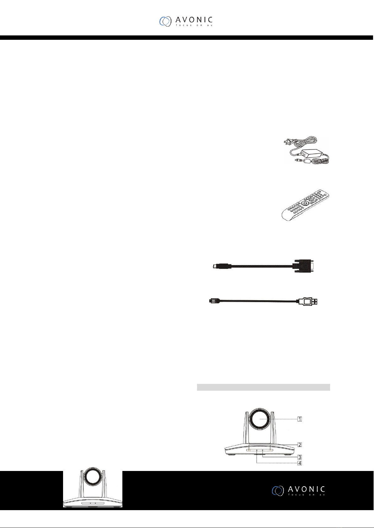
Packing List
When you open the package, please make
sure below items are included. If any items is
missing, please contact your supplier.
PTZ Camera x 1
Power Adapter x 1
Remote Control x 1
RS-232 Control Cable x 1
USB3.0 Cable x 1
manual(1)
Main Parts and Control
Interfaces
PTZ Camera
Front Part
1 Camera Module
www.avonic.eu
6
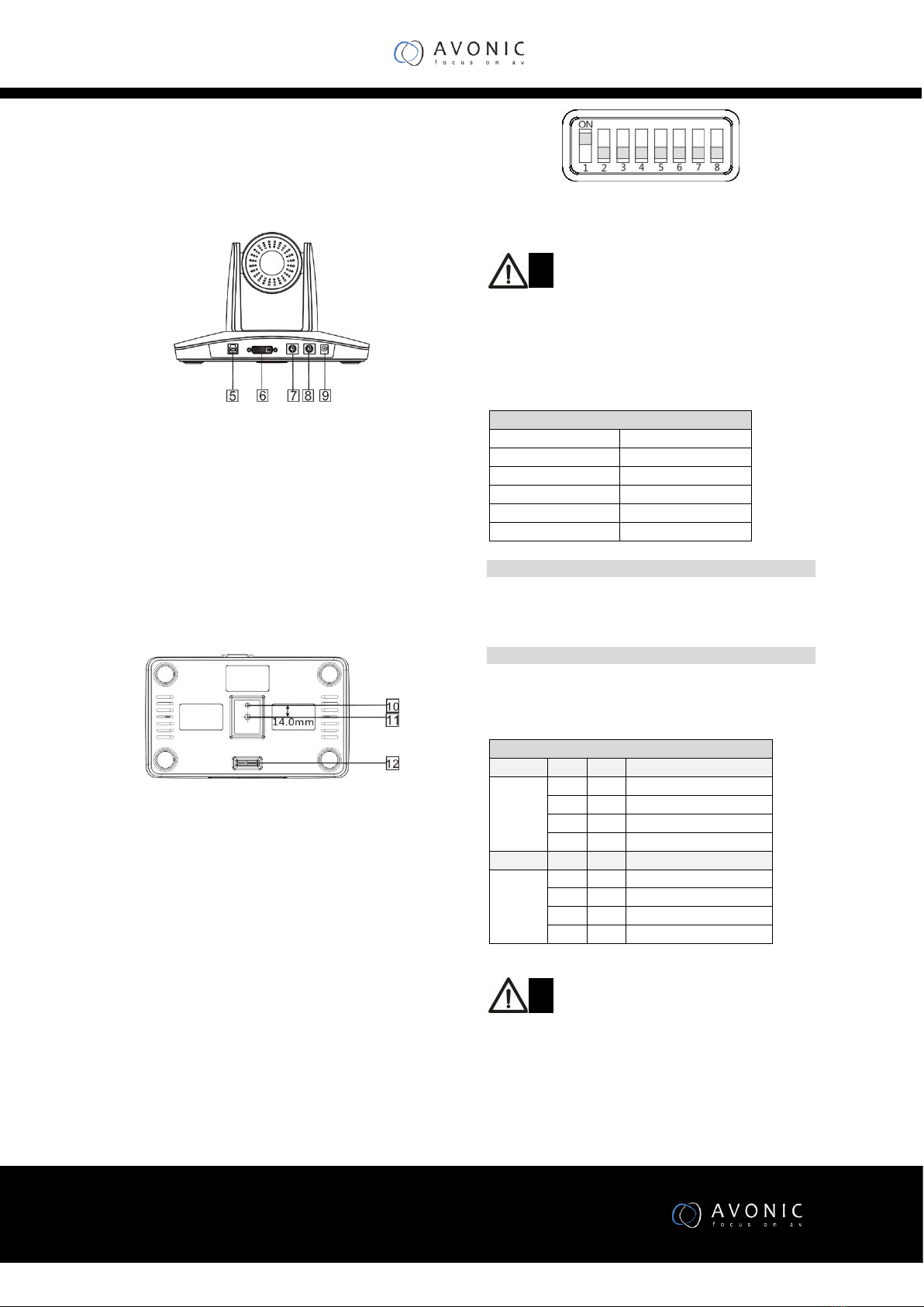
2 Remote Control Sensor
3 Power Indicator
4 Communication Indicator
Rear Part
5 USB3.0
6 DVI
7 RS-232IN/IR
8 RS-232OUT/RS-485
9 Power Input(DC12V)
Bottom Part
10 Locating Hole
Used to define installation direction of the camera.
11 Installation Hole
1/4” inch screw, used to fix the camera.
12 DIP Switch
Used to set address, protocol, baud rate and other parameters.
DIP Switch Setting
Before operating the camera, please set camera’s address, baud
rate protocol and etc. through its DIP switch located at the
bottom part of the camera. There are two switches named SW1
and SW2.
Note
The SW1 and SW2 switches look the same, their settings are
different. SW1 is used to set camera’s address and mounting
types, while SW2 is used to set camera’s control protocol and
baud rate
Default Settings
Camera Address
1
Baud Rate
9600bps
Protocol
VISCA
Video Output Format
1080P25
Mounting Type
Stand
SW1 Settings
Use DIP1 to DIP6 to set 64 address accordingly. DIP7 is reserved.
DIP8 is used to set camera’s mounting type. Please refer to Annex
3 for detailed SW1 definitions.
SW2 Settings
Use SW2 to set camera’s protocol, baud rate. Use DIP1 and DIP2
to set camera’s protocol, use DIP 3 and DIP4 to set camera’s
baud rate. DIP5~DIP8 switches are reserved.
Note
It requires a reboot of the PTZ for the switch setting to take
effect
SW2
DIP No.
1
2
Protocol
OFF
OFF
VISCA
ON
OFF
PELCO- D
OFF
ON
PELCO- P
ON
ON
-
DIP No.
3
4
Baud
Rate
OFF
OFF
2400
ON
OFF
4800
OFF
ON
9600
ON
ON
38400
www.avonic.eu
7
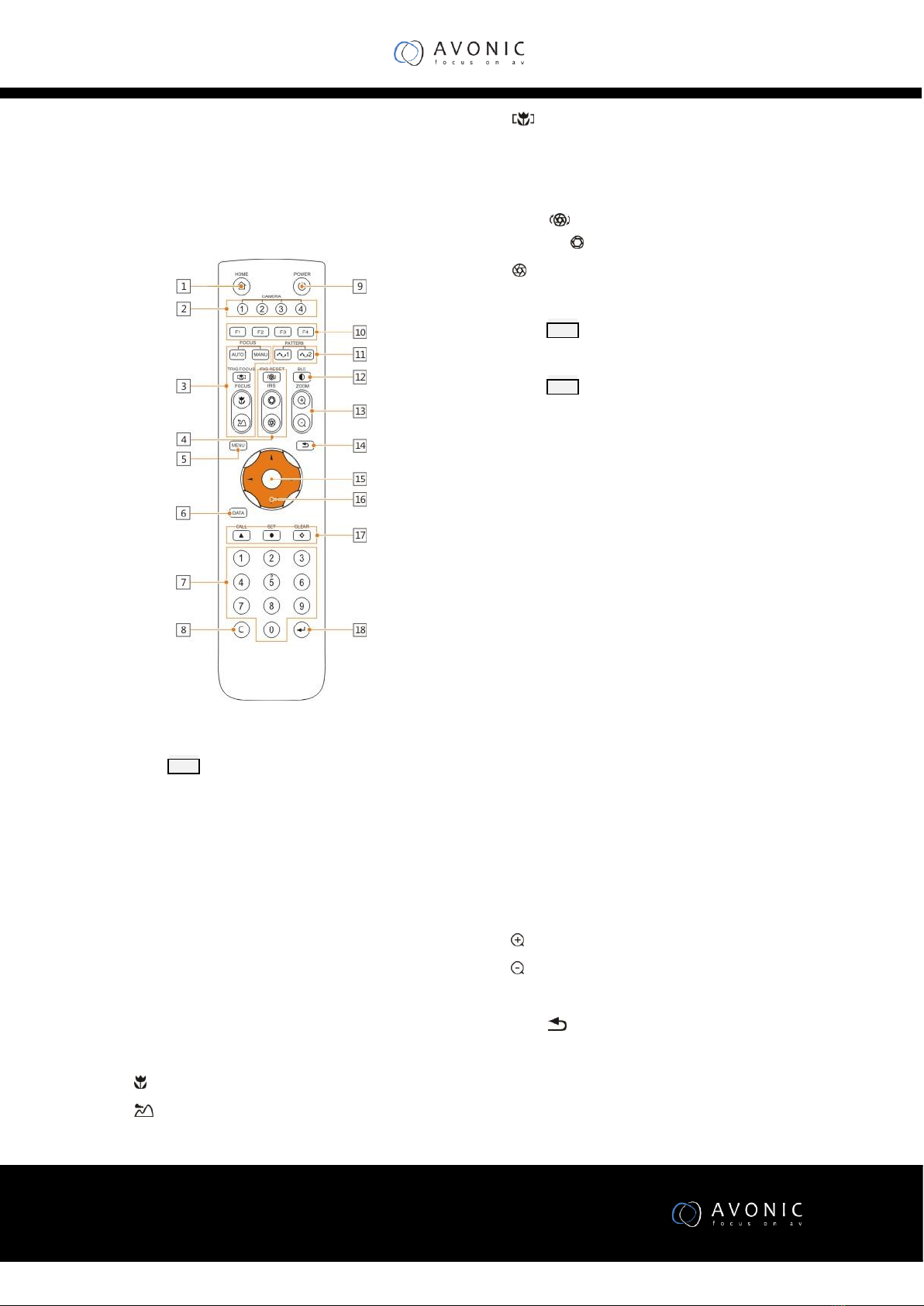
Remote Control
1 HOME button
Press HOME button, camera moves to initial
position where both pan and tilt angle is
zero.
2 Camera Selection Button
Used to switch among 4 cameras, press 1-4
number buttons to control cameras with 1-
4 address respectively. For example, press
button 1 to control the camera with address
1.
3 Focus
Press “AUTO” button to switch to Auto
Focus mode, press “MANU” button to
switch to Manual Focus mode.
“ ”button to Focus Near
“ ”button to Focus Far
“ ”button to Auto Focus once every time
it is pressed, then switch back to Manual
Focus mode.
4 Iris
Press“ ”button to reset iris value to
default. “ ”button to Iris Open
“ ”button to Iris Close.
5 Menu
Press MENU button to enter / exit menu.
6 Data
Press DATA button to turn on / off display of
pan tilt angel, zoom times and title info
7 Number Keys
Used to input numbers, for example, preset
number.
8 Cancel
Used to delete number inputted.
9 Power
After the camera has been connected to
power source, in none-menu status, press
this button to turn on / off the camera.
10 Reserved buttons(F1, F2, F3, F4)
These buttons are reserved for future use.
11 Pattern
Used to activate Pattern Scan1 and Pattern
Scan2.
12 BLC
Used to open / close back light
compensation.
13 Zoom
Used to adjust zooming times.
“ ”button to zoom in
“ ”button to zoom out.
14 Back
Press“ ”button to go back to previous
menu.
15 OK
In None-menu status: press this button to
switch among pan / tilt control speeds.
In Menu status: get into relative menu
option after it has been selected.

www.avonic.eu
8
16 Direction / Menu Operation
In None-menu status: press these four
buttons to pan left/right and tilt up/down.
In Menu status: or button to select
among menu options, or to change
option / value.
17 Preset Setting
“ ” button to call a preset.
Input number key(s), and then press this
button to call a preset.
“ ”button to set a preset.
Move the camera to a specific position,
adjust focus value and etc., and then press
this button to set a preset.
“ ”button to clear a preset.
Input number key(s), and then press this
button to clear a preset.
18 Enter
After inputting numbers, press this button
to confirm.
www.avonic.eu
9
Installation
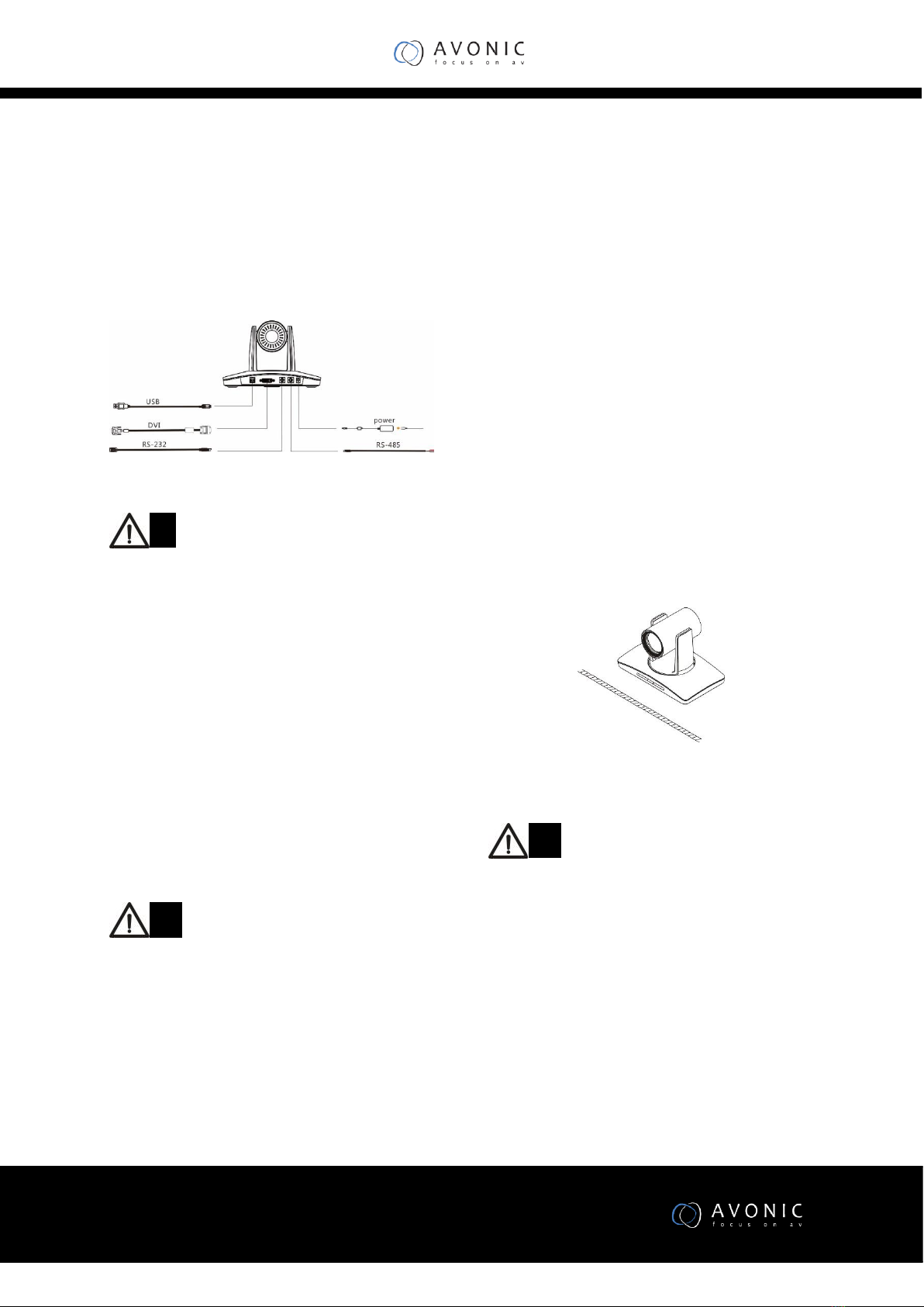
Cable Connecting
Note
If preset 0 has been saved, after powered on,
camera moves to preset 0 automatically; if
preset 0 has not been saved, after powered
on, camera moves to Home position, where
both pan and tilt angle is zero and zooming
time is 1x.
Mounting
The camera has 4 installation types: desktop,
wall (optional), ceiling (optional) and pole
(optional) mount installations.
Note
Before installing, make sure there is enough
space to install the camera and its parts.
Make sure the installed place is strong and
safe enough to hold the camera and relative
parts, it is suggested that the installed place
can withstand 4 times the weight of the
camera and its relative parts
Desktop Mount Installation
1.Put the camera on a flat surface. In case the camera
has to be placed on an inclined surface, make sure the
cline angle is less than 15 degrees to ensure proper
pan /tilt operation.
Note
Take effective measures to avoid camera
from dropping.
Do not grab the camera head when carrying.
Do not rotate the camera head with hand. It
may cause malfunction to the camera.
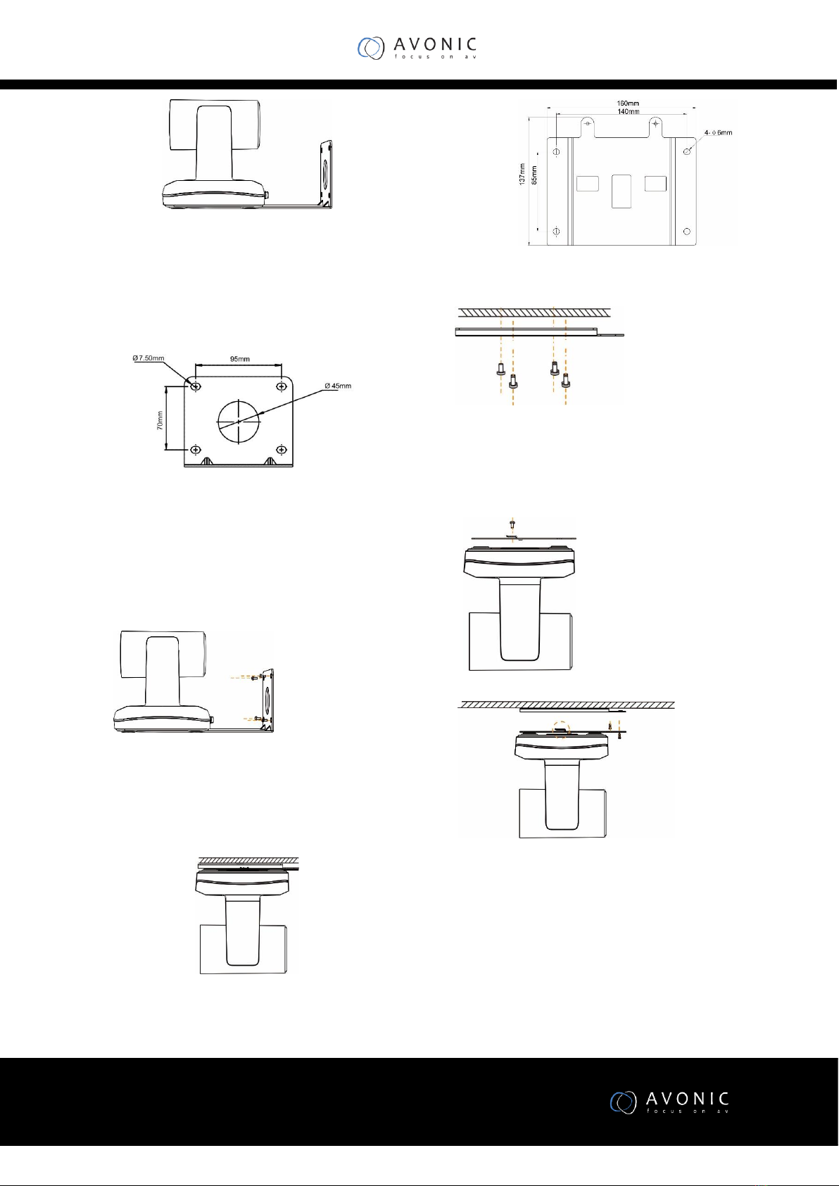
Wall Mount Installation
(Bracket not supplied with camera)
www.avonic.eu
10
1.According to diameter and position of the 4 installation
holes (As shown below) on the bracket, drill 4 holes on
the wall and fix the bracket onto the wall by using 4
screws which should be prepared by yourself.
1.Before fixing the camera, set the DIP switches of the
camera correctly.
2.Use inch screws to fix the camera on the bracket, fix
the limit screw
3.According to actual requirement, and make sure the
camera is tightly fixed onto the bracket before your
hands leave the camera.
Ceiling Mount Installation
(Bracket not supplied with camera)
1.According to diameter and position of the 4 installation
holes (As shown below) on the bottom plate, drill 4
holes on the ceiling.
2.Fix the plate onto the ceiling by using 4 screws which
should be prepared by yourself.
3.Before fixing the camera, set the DIP switches of the
camera correctly.
4.Use inch screws to fix the bottom plate on the ceiling,
fix the limit screw
5.Slide the PTZ camera via the slot of the plate and fix
the camera to the plate.

www.avonic.eu
11
www.avonic.eu
12
Menu Settings
Menu Explanation
Press MENU button to enter / exit menu.
❶Menu Hint
It displays currently selected menu option.
❷Menu Options
It displays options under current menu
hint.
Press or button to select among menu
options, once font of options turned from
white color to yellow color, it
From main menu, navigate to select
<EXPOSURE> menu, press OK to enter.
❶❷ Refer to Main Menu
explanations.
❸Manual Exposure
Press or button to change value
Video
VIDEO is used to change video value.
Available Options:
SHARPNESS : 0 - 15.
CONTRAST : 0 - 14.
SATURATION : 0 - 14.
HUE : 0 - 14.
2DNR LEVEL : OFF, ON
If camera displays color image, it is suggested
to turn off the 2DNR level, otherwise, the
video trails will be generated. The higher the
level is, the better is the noise reduction
performance, but more video trails will be
generated.
3DNR LEVEL: OFF, AUTO, 1,2,3,4.
WIDE DYNAMIC: ON, OFF
<MENU>
VIDEO
EXPOSURE
WHITE BALANCE
PAN TILT ZOOM
SYSTEM
STATUS
RESTORE DEFAULTS
<EXPOSURE>
MODE MANUAL
GAIN 0
SPEED 1/1
IRIS F14
EXP-COM ON
LEVEL 0
BLC ON
ANTI FLICKER OFF
<VIDEO>
SHARPNESS 8
CONTRAST 2
SATURATION 5
HUE 0
2DNR LEVEL2D OFF
3DNR LEVEL 3D OFF
WIDE DYNAMIC OFF

www.avonic.eu
13
Exposure
EXPOSURE menu is used to adjust exposure
value.
<EXPOSURE>
MODE MANUAL
GAIN 0
SPEED 1/1
IRIS F14
EXP-COMP ON
LEVEL 0
BLC ON
ANTI FLICKER OFF

www.avonic.eu
14
Available Options:
MODE
FULL AUTO: Gain, Shutter Speed and Iris value
are adjusted automatically accordingly to
working environment.
MANUAL: manually adjust Gain, Shutter
Speed and Iris
GAIN: 0 - +30
SPEED: 1/1 - 1/10000.
IRIS: F14 - F1.6, CLOSE.
SHUTTER PRI: Gain and Iris value are adjusted
automatically according to working
environment; shutter speed value is
adjustable manually.
SPEED: 1/1 - 1/10000.
IRIS PRI: Gain and shutter speed value are
adjusted automatically according to working
environment; Iris value is adjustable manually.
IRIS: F14 - F1.6, CLOSE.
EXP-COMP: once EXP-COMP is set as On,
below level options become available -7 - +7 is
the maximum compensation value for bright, -
7 is the maximum compensation value for
dark.
BLC: ON, OFF
Backlight compensation (BLC) is video gain
done automatically to correct the exposure of
subjects that are in front of a bright light
source.
ANTI-FLICKER:OFF, 50HZ, 60HZ
This option is used to address the image
flicker issue when camera is used in different
lighting environment.
White Balance
WHITE BALANCE menu is used to select from
white balance modes.
Available Options:
MODE: AUTO, ATW(auto tracking), ONE
PUSH, INDOOR, OUTDOOR), MANUAL,
SODIUM LAMP, FLUO LAMP.
“ONE PUSH”: When in “ONE PUSH
TRIGGER” mode, aim the camera at a pure
white object (say a white paper), then press
OK button.
“MANUAL”: R.GAIN and B. GAIN value can be
chosen from 0~255
Pan/Tilt/Zoom
PAN/TILT/ZOOM is used to change
pan/tilt/zoom value
.
Available Options:
PAN/TILT SPEED: 1, 2, 3, 4, 5, 6, 7, 8 the bigger
the number is, the faster the speed is. The
speed is the fastest when in 1x zoom
compared to other zooming times.
PAN/TILT LIMIT: ON/OFF, once it is set as ON,
below limit value can be set
UP: -30°~+90°, adjustable every 1°;
DOWN: -30°~+90°, adjustable every 1°;
LEFT: -170°~+170°, adjustable every 1°;
LIGHT: -170°~+170°, adjustable every 1°.
D-ZOOM LIMIT: X1, X2, X3, X4, X5, X6,
<WHITE BALANCE>
MODE MANUAL
R.GAIN 1
B.GAIN 128
<PAN TILT ZOOM>
PAN/TILT SPEED 8
PAN/TILT LIMIT ON
UP +90
DOWN 30
LEFT +170
RIGHT 170
D-ZOOM LIMIT X4
PTZ TRIG AF OFF
POWER UP ACTION HOME
www.avonic.eu
15
PTZ TRIG AF: Turn ON / OFF the auto focus
when the camera pans / tilts / zooms.
POWER UP ACTION: PRESET 1, PRESET 2,
PRESET 3, PRESET 4, PRESET 5, PRESET 6,
PRESET 7, PRESET 8, PRESET 9, HOME.
System
FORMAT:
1920x1080P/60/50/30/25/20/15/10/5
1280x720P/60/50/30/25/20/15/10/5
1024x768P/60/50/30/25/20/15/10/5
800x600P/60/50/30/25/20/15/10/5
640x480P/60/50/30/25/20/15/10/5.
Note
The videos from USB and DVI-D are
simultaneously output only at
1080P60/50/30/25, 720P60/50/30/25.
When the videos from USB and DVI-D are
simultaneously output, Video from USB may
not be output when the DVI-D video formats
are changed via menu or preset.
The format change of USB video will change
the format of DVI-D video. When the format
of USB video is changed to one that is not
supported by DVI-D video, The DVI-D video
will not be output.
RATIO SPEED:ON, OFF
When RATIO SPEED is set as ON, pan speed
changes automatically based on zooming
times, that is, the more zooming times, the
PRESET FREEZE:ON, OFF
When it is on, during a regular preset call, the
video will be frozen at point A till Point B. At
Point B, the video will be displayed normally.
RS-485(RS-485 modes)
HALF-DUPLEX-1: in VISCA protocol, camera
will not return confirmation, completion or
error messages after commands have been
executed.
HALF-DUPLEX-2: in VISCA protocol, camera
will return confirmation, completion or
error messages after commands have been
executed.
DISPLAY INFO: Turn ON / OFF display of pan /
tilt angle and prompt message.
Status
It displays current camera’s address,
protocol, baud rate, video format, mount
mode and software version number.
Restore Defaults
RESTORE DEFAULTS:This option is used to
reset all menus to default value. Press OK to
<SYSTEM>
FORMAT 640 x 480P60
RATIO SPEEDON PRESET FREEZE
OFF
RS485PORT HALF-DUPLEX-1
DISPLAY INFO OFF
<STATUS>
ADDRESS 1
PROTOCOL VISCA
BAUD RATE 9600
FORMAT 640 x 480P30
MOUNT STAND
IMAGE VER V1606
USB VER V1.0.0
FIRMWARE V1.0.0
< RESTORE DEFAULTS>
PRESS OK CONFIRM
PRESS BACK CANCEL
www.avonic.eu
16
confirm or press to cancel and return to
previous menu.
Special Preset Commands
No
Setting
93
Cruise, camera switches among saved 0~29
presets repeatedly and sequentially in fixed
interval.
95
Get into menu
96
Delete all presets
99
Reboot the camera
100
1920X1080P50
101
1920X1080P25
103
1280X720P50
104
1280X720P25
105
1920X1080P60
106
1920X1080P30
108
1280X720P60
109
1280X720P30
Annex 1 Technical Specifications
Image Sensor
1/2.8" CMOS, 2.14 megapixel
Video Format
USB3.0:
1920x1080P/60/50/30/25/20/15/10/5
1280x720P/60/50/30/25/20/15/10/5
1024x768P/60/50/30/25/20/15/10/5
800x600P/60/50/30/25/20/15/10/5
640x480P/60/50/30/25/20/15/10/5
USB2.0 :
1920x1080P5;
1280x720P10/5;
800x600P30/25/20/15/10/5
640x480P30/25/20/15/10/5
DVI-D:
1920x1080P/60/50/30/25
1280x720P/60/50/30/25
Focal Lens
f=3.9-46.8mm
Iris
F1.6-F2.8
Optical Zoom
12x
Digital Zoom
12x
Field of View
72.5°-6.3°
Focus System
Auto, Manual, PTZ trigger, One push trigger
Min.Illumination
0.5 lux (color),0.1Lux (B/W)
Shutter Speed
1/1 to 1/10,000s
Gain
Auto / Manual
White Balance
Auto, indoor, outdoor, one push, manual, auto tracking
Wide Dynamic
Yes

www.avonic.eu
17
Exposure
Control
Auto, Manual, Shutter Priority, Iris Priority
S/N
≥50dB
Pan Angle
-170°~+170°
Tilt Angle
-30°~+90°
Pan Speed
0.1°~120°/S
Tilt Speed
0.1°~80°/S
Preset Number
256
OSD
Yes
Image Flip
Yes
HD Video
Output
USB3.0,DVI-D
Control Interface
USB3.0,RS-232IN,RS-232OUT,RS-485
UVC Protocol
UVC 1.1
UVC PTZ
Control
Yes
Protocol
VISCA (supports daisy chain) / PELCO-P / PELCO-D
Address
VISCA: 0~7 / PELCO: 0~63
Power
DC12V
Power
Consumption
<20W
Operating
Temperature
0°C~+40°C
Storage
Temperature
-20°C~+60°C
Dimensions
(W×D×H)
243mm×145mm×163mm
Weight
1.2KG
Body Color
Grey

www.avonic.eu
18
Annex 2 Size and Dimension
Front
Rear
Top
Side
Bottom
www.avonic.eu
19
Annex 3 SW1 Definition
SW1 DIP
Address
1
2
3
4
5
6
0
OFF
OFF
OFF
OFF
OFF
OFF
1
ON
OFF
OFF
OFF
OFF
OFF
2
OFF
ON
OFF
OFF
OFF
OFF
3
ON
ON
OFF
OFF
OFF
OFF
4
OFF
OFF
ON
OFF
OFF
OFF
5
ON
OFF
ON
OFF
OFF
OFF
6
OFF
ON
ON
OFF
OFF
OFF
7
ON
ON
ON
OFF
OFF
OFF
8
OFF
OFF
OFF
ON
OFF
OFF
9
ON
OFF
OFF
ON
OFF
OFF
10
OFF
ON
OFF
ON
OFF
OFF
11
ON
ON
OFF
ON
OFF
OFF
12
OFF
OFF
ON
ON
OFF
OFF
13
ON
OFF
ON
ON
OFF
OFF
14
OFF
ON
ON
ON
OFF
OFF
15
ON
ON
ON
ON
OFF
OFF
16
OFF
OFF
OFF
OFF
ON
OFF
17
ON
OFF
OFF
OFF
ON
OFF
18
OFF
ON
OFF
OFF
ON
OFF
19
ON
ON
OFF
OFF
ON
OFF
20
OFF
OFF
ON
OFF
ON
OFF
21
ON
OFF
ON
OFF
ON
OFF
22
OFF
ON
ON
OFF
ON
OFF
23
ON
ON
ON
OFF
ON
OFF
24
OFF
OFF
OFF
ON
ON
OFF
25
ON
OFF
OFF
ON
ON
OFF
26
OFF
ON
OFF
ON
ON
OFF
27
ON
ON
OFF
ON
ON
OFF
28
OFF
OFF
ON
ON
ON
OFF
29
ON
OFF
ON
ON
ON
OFF
www.avonic.eu
20
30
OFF
ON
ON
ON
ON
OFF
31
ON
ON
ON
ON
ON
OFF
32
OFF
OFF
OFF
OFF
OFF
ON
33
ON
OFF
OFF
OFF
OFF
ON
34
OFF
ON
OFF
OFF
OFF
ON
35
ON
ON
OFF
OFF
OFF
ON
36
OFF
OFF
ON
OFF
OFF
ON
37
ON
OFF
ON
OFF
OFF
ON
38
OFF
ON
ON
OFF
OFF
ON
39
ON
ON
ON
OFF
OFF
ON
40
OFF
OFF
OFF
ON
OFF
ON
41
ON
OFF
OFF
ON
OFF
ON
42
OFF
ON
OFF
ON
OFF
ON
43
ON
ON
OFF
ON
OFF
ON
44
OFF
OFF
ON
ON
OFF
ON
45
ON
OFF
ON
ON
OFF
ON
46
OFF
ON
ON
ON
OFF
ON
47
ON
ON
ON
ON
OFF
ON
48
OFF
OFF
OFF
OFF
ON
ON
49
ON
OFF
OFF
OFF
ON
ON
50
OFF
ON
OFF
OFF
ON
ON
51
ON
ON
OFF
OFF
ON
ON
52
OFF
OFF
ON
OFF
ON
ON
53
ON
OFF
ON
OFF
ON
ON
54
OFF
ON
ON
OFF
ON
ON
55
ON
ON
ON
OFF
ON
ON
56
OFF
OFF
OFF
ON
ON
ON
57
ON
OFF
OFF
ON
ON
ON
58
OFF
ON
OFF
ON
ON
ON
59
ON
ON
OFF
ON
ON
ON
60
OFF
OFF
ON
ON
ON
ON
61
ON
OFF
ON
ON
ON
ON
62
OFF
ON
ON
ON
ON
ON
63
ON
ON
ON
ON
ON
ON
DIP No.
7
Table of contents


