manuals.online logo
Brands
  1. Home
  2. •
  3. Brands
  4. •
  5. AweSome
  6. •
  7. Musical Instrument
  8. •
  9. AweSome Telecaster User manual

AweSome Telecaster User manual

© 2010, AweSome Musical Instruments, All rights reserved worldwide 1 Telecaster Control Plate Upgrade www.AweSome-Guitars.com
Telecaster Upgrade Installation Instructions Revised: June 6, 2014
Before you start, read these instructions first to understand what you need to do to install this product.
Assumptions
This patented Pickup Switch UpgradeTM product is
designed to use only one Volume and one Tone
control for all of your instrument’s pickups. These
products are designed to control 2, 3 or 4 magnetic
pickup coils. Note: Active (uses batteries) or Pizeo
pickups cannot be used with this product.
Tools Needed
You may need one or more of the following tools
(not included with purchase) to install this Pickup
Switch UpgradeTM product (see each product for
additional specific tool requirements).
•Wire cutters / Wire strippers
•Regular pliers
•Small Phillips & straight slot screwdriver (a
4-way screwdriver can be used as a deep-
well socket to remove switch mounting nuts.
•Ohmmeter to measure continuity
•Optional: rotary file and electric drill
•Optional: Soldering iron (25/30 watt max.)
with fine tip, rosin-core solder .022” dia.
Preamble
Although not required for this product, you might
want to completely remove all strings from your
instrument for easy access to its parts. The strings
are probably already old and replacing them will
make your instrument sound even more brilliant
after you install this product.
This Telecaster Control Plate Upgrade will have
you cutting existing wires on your instrument. You
may need to make wire connections, increase the
length of existing wires, and remove some wood in
your instrument body cavity.
Because you will be making several changes to your
instrument, you need to have a plan to install this
revolutionary Pickup Switch UpgradeTM product.
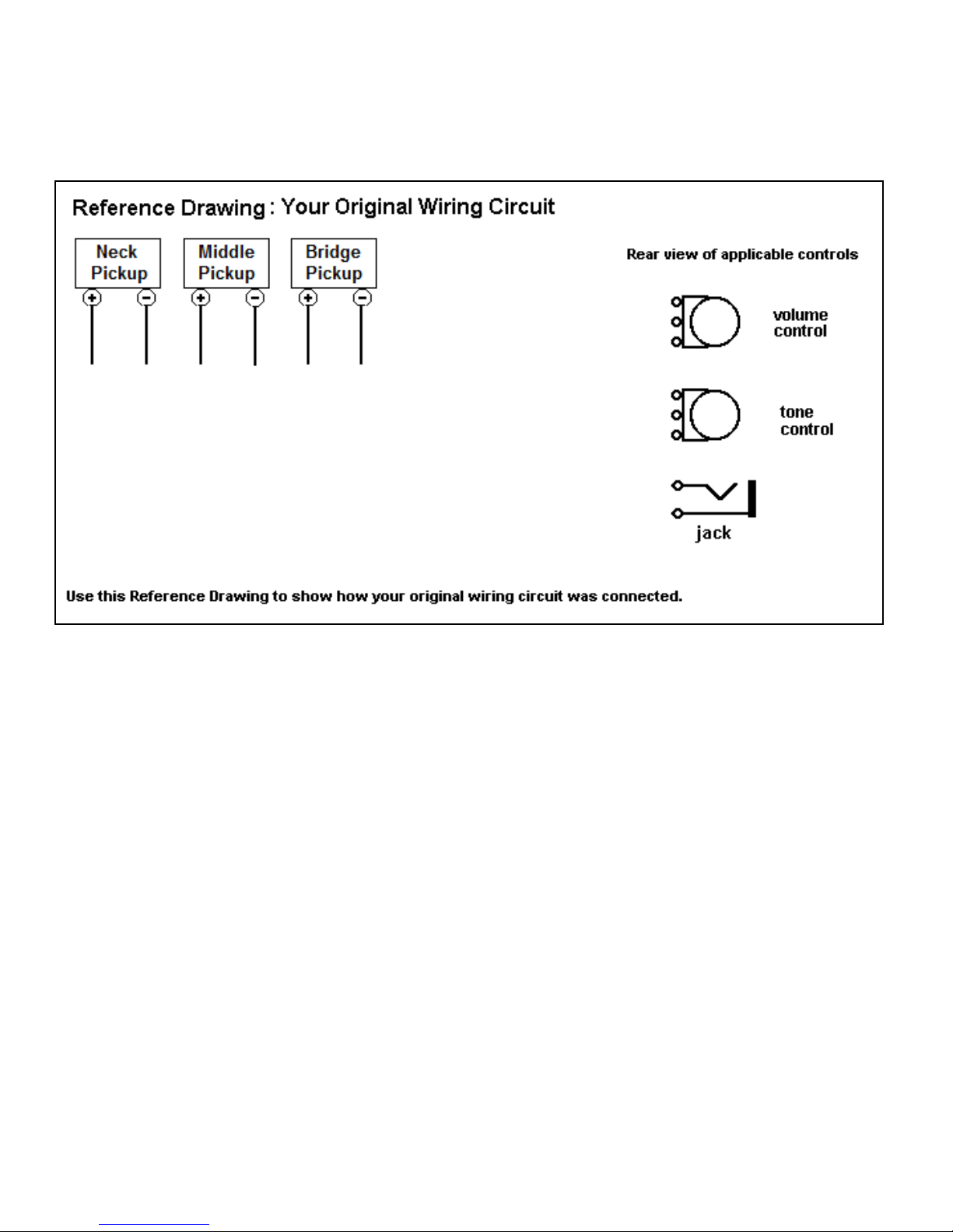
See the Reference Drawing on a later page of this
document. Use a pencil to draw the original circuit
of your instrument before you proceed. When you
record where the wires (and colors) were removed
from your instrument, you have a way to restore it
to its original condition should it become necessary.
Since there is a large variation of pickup switch
wiring that spans 50 years, you will need to draw
your own pickup switch used in your original circuit
Adding Extra Wire
If your pickup or input wires are too short to easily
reach the specified connection of the green terminal
strip on the Pickup Switch UpgradeTM circuit
board, here is what to do. Measure out the needed
length of the RED or BLACK wire in the included
PARTS BAG to permit the wire to reach the applicable
connection. A length of 3” (7.62cm) is budgeted for
each wire extension. Insert the unstripped end of
each wire into the 2-wire UY2 yellow/clear
connector and clamp down using regular pliers.
Use pliers to squeeze the UY2 connector top button
so it is flush with the body to create a permanent
electrical connection. Verify electrical continuity
between the two pickup wires using an ohmmeter
(some coil resistance will be present). The 71B grey
wire nuts are used to make the needed firm and
insulated connection to the input jack wires, but let
you disconnect the installation if needed.
Note: If either your pickup or input wires use a
shielded/braided cable, you will need to solder
black wire to the cable because the green terminal
strip (J1) does not directly accept shielded cable.
Product Variants
Your installation will involve one of the following
upgrade products. This document contains
information specific to one of these products.
1. Pickup Switch Upgrade Board
2. Telecaster Upgrade
3. Stratocaster Upgrade
4. Jazz Bass Upgrade
© 2010, AweSome Musical Instruments, All rights reserved worldwide 2 Telecaster Control Plate Upgrade www.AweSome-Guitars.com
2. TELECASTER UPGRADE
You have received an assembled and tested Telecaster Upgrade designed to install into a standard American
Telecaster guitar. It contains one of our high performance Pickup Switch UpgradeTM products, one tone and
volume control with matching knobs. No soldering is needed to install this product. You will use your own
pickups. The following items are included in a Parts Bag.
•An AweSome Musical Instruments headstock decal to apply to your instrument
•Several business cards to pass out to friends
•An equal length each of black and red insulated wire (to lengthen pickup and input jack wire if needed)
•2 or 4 yellow/clear connectors (UY2) to make pickup wire extension connections if needed
•2 grey wire nuts (71B) to connect input jack wires to your Telecaster control plate upgrade product
Preparation
If needed, remove your strings. Remove your existing control plate attaching screws. Lift it out and document
how your instrument is wired (see Preamble on page 1) before you start this upgrade.
Disconnect the input jack hot and ground wires from your stock control plate. The wires stay on the input jack.
Cut the pickup wires from the 3-way (or 5-way) pickup switch so all wires are of maximum length. If needed,
disconnect the bridge ground wire. Remove your original control plate. Temporarily stow the input jack wires
and pickup wires within the body cavity.
Confirm that the Telecaster Upgrade will lay completely flat and within the routed body cavity with no
interference by the wood body. If the Telecaster Upgrade lays flat on your instrument and the plate mounting
holes line up with the body mounting holes, proceed to the next section, Terminal Strip, to continue with the
upgrade process.
If your Telecaster Upgrade mounting holes and body mounting holes do not line up, or you have a control
plate body cavity with a non-standard dimension preventing the upgrade product from being installed, see page
10 – Solving Installation Issues for information that identifies how to easily resolve these issues.
Terminal Strip
Here is how to attach wires to the green terminal strip (J1) that is on the PTM circuit board. Use a small
screwdriver or writing pen tip and press down on the square release button located directly above the wire hole.
Hold the button down and insert the stripped wire completely into the wire connection hole and then release the
button. Lightly tug on the wire to confirm it is firmly gripped by the Terminal Strip. A legend is printed on the
circuit board with the name of each terminal strip wire hole from left to right. Attach each wire to the correct
terminal strip hole. In all instances, the GND and VOL wires from the Volume/Tone control circuit displayed in
Figure 2 to the wire connection holes on the terminal strip are already connected.
T2-Switch (6-hole terminal strip): [GND] [VOL] [+]NECK[-] [+]BRDG[-]
T3-Switch (8-hole terminal strip): [GND] [VOL] [+]Coil-3[-] [+]Coil-2[-] [+]Coil-1[-]
T4-Switch (10-hole terminal strip): [GND] [VOL] [+]NECK2[-] [+]NECK1[-] [+]BRDG2[-] [+]BRDG1[-]
Caution: Do not insert hard items in the wire holes because it will decrease reliable electrical connection.
© 2010, AweSome Musical Instruments, All rights reserved worldwide 3 Telecaster Control Plate Upgrade www.AweSome-Guitars.com
Connecting Your Wires
There is no industry standard for pickup wire lead colors. More common color pairs are red/black, red/white,
black/white and white/shield. You are advised to use consistency when connecting your pickup wire color pairs
to the [+] and [–] pickup connections on the green terminal strip (J1).
Determine which wire color for each pickup coil will be attached to the applicable [+] and [–] green terminal
strip connector on our PTM board. If one of the pickup wire connections is a shielded lead, always connect the
shield to a BLACK [–] wire to be inserted in the green terminal strip on our switching system.
Determine if there is enough wire length from each 2-wire pickup coil to comfortably reach the corresponding
connectors on the green terminal strip on the Pickup Switch UpgradeTM circuit board. If not, refer to the
“Adding Extra Wire” topic (page 1).
WARNING: If your pickups have a metal bottom and if either pickup coil wire is grounded to this housing
(use an ohmmeter to check each wire to body), make sure your instrument’s body cavity is not lined with
grounded metal shielding and the pickup housing does not have a separate grounding wire. Reason: This will
cause the pickup to “short” to ground when the pickup switch is put into the regular/reverse phase. To fix this,
isolate the pickup housing from the body cavity shielding with soft foam.
Strip off 3/16” (4.76mm) insulation from the end of each pickup wire and also the input jack wires then twist
the exposed wire strands so they are tightly bound. Insert the wires of each pickup pair into the correct location
on the green terminal strip (J1) using the process described in the above “Terminal Strip” topic. Attach the
wires using either of the following instructions.
Use the two gray wire nuts (71B) to connect the wires labeled “IN” to the wires on your input jack. The red
wire goes to the hot lead (normally red) on the input jack and the black wire goes to the ground lead on the
input jack.
Note: If you have a ground wire coming from the bridge (and maybe from body cavity shielding), connect them
to ground lead on the input jack.
© 2010, AweSome Musical Instruments, All rights reserved worldwide 4 Telecaster Control Plate Upgrade www.AweSome-Guitars.com
Connecting your pickups to the TCP-T2 Telecaster Upgrade
Connect your NECK pickup coil wire pair to the [+]NECK[-] connections on the green terminal strip
Connect your BRIDGE pickup coil wire pair to the [+]BRDG[-] connections on the green terminal strip
TCP-T2 Telecaster Upgrade Switch Identification and Use Summary
Here is a summary of switch use for this product (see Figure 1 for switch identification).
Document #A will help you “map” the pickup tones you get from the T2-Switch. It is available for download
from our website’s Document Library at http://www.AweSome-Guitars.com
SW1 and SW3 are ON-OFF-ON switches that turn on individual pickups in normal or reverse phase
SW5 is an ON-ON switch that changes the pickups from Parallel to Series connectivity
For a Right-Handed Instrument:
SW1 turns on the bridge pickup, either in normal phase (down), or reverse phase (up).
SW3 turns on the neck pickup, either in normal phase (down), or reverse phase (up).
SW5 When this switch is down, the pickups will be in a Parallel circuit.
When this switch is up it puts the bridge and neck pickups in a Series circuit. Both pickups must be on,
either in normal phase(down) or reverse phase (up) or no sound will be produced.
For a Left-Handed Instrument:
SW1 turns on the bridge pickup, either in normal phase (down), or reverse phase (up).
SW3 turns on the neck pickup, either in normal phase (down), or reverse phase (up).
SW5 When this switch is up, the pickups will be in a Parallel circuit.
When this switch is down it puts the bridge and neck pickups in a Series circuit. Both pickups must be
on, either in normal phase(down) or reverse phase (up) or no sound will be produced.
© 2010, AweSome Musical Instruments, All rights reserved worldwide 5 Telecaster Control Plate Upgrade www.AweSome-Guitars.com
Connecting your pickups to the TCP-T3 Telecaster Upgrade
Connect your NECK pickup coil wire pair to the [+]Coil-3[-] connections on the green terminal strip
Connect your MIDDLE pickup coil wire pair to the [+]Coil-2[-] connections on the green terminal strip
Connect your BRIDGE pickup coil wire pair to the [+]Coil-1[-] connections on the green terminal strip
TCP-T3 Telecaster Upgrade Switch Identification and Use Summary
Here is a summary of switch use for this product (see Figure 1 for switch identification).
Document #B will help you “map” the pickup tones you get from the T3-Switch. It is available for download
from our website’s Document Library at http://www.AweSome-Guitars.com
SW1, SW2 and SW3 are ON-OFF-ON switches that turn on individual pickups in normal or reverse phase
SW4, SW5 and SW6 are ON-ON switches that change select pickups from Parallel to Series connectivity
For a Right-Handed Instrument:
SW1 turns on the bridge pickup, either in normal phase (down), or reverse phase (up).
SW2 turns on the middle pickup, either in normal phase (down), or reverse phase (up).
SW3 turns on the neck pickup, either in normal phase (down), or reverse phase (up).
When all of the following switches are down, the pickups will be in a Parallel circuit.
SW4 when switch is up it puts the bridge and middle pickups in Series. Both pickups must be on.1
SW5 when switch is up it puts the bridge and neck pickups in Series. Both pickups must be on.1
SW6 when switch is up it puts the neck and middle pickups in Series. Both pickups must be on.1
SW4+SW6 when these switches are up, all three pickups in Series. All pickups must be on or no sound will be
produced. SW5 has no effect.
1 The remaining non-series pickup may be either off -or- on (either in regular or reverse phase).
For a Left-Handed Instrument:
SW1 turns on the bridge pickup, either in normal phase (down), or reverse phase (up).
SW2 turns on the middle pickup, either in normal phase (down), or reverse phase (up).
SW3 turns on the neck pickup, either in normal phase (down), or reverse phase (up).
When all of the following switches are up, the pickups will be in a Parallel circuit.
SW4 when switch is down it puts bridge and middle pickups in Series. Both pickups must be on.1
SW5 when switch is down it puts the puts bridge and neck pickups in Series. Both pickups must be on.1
SW6 when switch is down it puts the puts neck and middle pickup in Series. Both pickups must be on.1
SW4+SW6 when these switches are down, all three pickups in Series. All pickups must be on or no sound will
be produced. SW5 has no effect.
1 The remaining non-series pickup may be either off -or- on (either in regular or reverse phase).
© 2010, AweSome Musical Instruments, All rights reserved worldwide 6 Telecaster Control Plate Upgrade www.AweSome-Guitars.com
Connecting your pickups to the TCP-T4 Telecaster Upgrade
If you are using two 4-wire humbucker pickups:
Connect your NECK1 pickup coil wire pair to the [+]NECK1[-] connections on the green terminal strip
Connect your NECK2 pickup coil wire pair to the [+]NECK2[-] connections on the green terminal strip
Connect your BRIDGE1 pickup coil wire pair to the [+]BRDG1[-] connections on the green terminal strip
Connect your BRIDGE2 pickup coil wire pair to the [+]BRDG2[-] connections on the green terminal strip
If you are using two single-coil pickups and one 4-wire humbucker pickup:
Connect your NECK pickup coil wire pair to the [+]NECK1[-] connections on the green terminal strip
Connect your MIDDLE pickup coil wire pair to the [+]NECK2[-] connections on the green terminal strip
Connect your BRIDGE1 pickup coil wire pair to the [+]BRDG1[-] connections on the green terminal strip 1
Connect your BRIDGE2 pickup coil wire pair to the [+]BRDG2[-] connections on the green terminal strip 1
1 Assumes that the bridge pickup position contains a 4-wire humbucker pickup
TCP-T4 Telecaster Upgrade Switch Identification and Use Summary
Here is a summary of switch use for this product (see Figure 1 for switch identification).
Document #C will help you “map” the pickup tones you get from the T4-Switch. It is available for download
from our website’s Document Library at http://www.AweSome-Guitars.com
S1N, S2N, S1B and S2B are ON-OFF-ON switches that turn on individual pickups in normal or reverse phase
S5N and S5B are ON-ON switches that change select pickup coils from Parallel to Series connectivity
For a Right-Handed Instrument:
S1B turns on BRIDGE1 pickup coil, either in normal phase (down), or reverse phase (up).
S2B turns on BRIDGE2 pickup coil, either in normal phase (down), or reverse phase (up).
S5B When this switch is down, both bridge pickup coils will be in a Parallel circuit.
When this switch is up it puts BRIDGE1 and BRIDGE2 pickup coils in a Series circuit. Both pickup
coils must be on, either in normal phase (down) or reverse phase (up) or no sound will be produced.
S1N turns on NECK1 pickup coil, either in normal phase (down), or reverse phase (up).
S2N turns on NECK2 pickup coil, either in normal phase (down), or reverse phase (up).
S5N When this switch is down, both neck pickup coils will be in a Parallel circuit.
When this switch is up it puts NECK1 and NECK2 pickup coils in a Series circuit. Both pickup coils
must be on, either in normal phase (down) or reverse phase (up) or no sound will be produced.
For a Left-Handed Instrument:
S1B turns on BRIDGE1 pickup coil, either in normal phase (down), or reverse phase (up).
S2B turns on BRIDGE2 pickup coil, either in normal phase (down), or reverse phase (up).
S5B When this switch is up, both bridge pickup coils will be in a Parallel circuit.
When this switch is down it puts BRIDGE1 and BRIDGE2 pickup coils in a Series circuit. Both pickup
coils must be on, either in normal phase (down) or reverse phase (up) or no sound will be produced.
S1N turns on NECK1 pickup coil, either in normal phase (down), or reverse phase (up).
S2N turns on NECK2 pickup coil, either in normal phase (down), or reverse phase (up).
S5N When this switch is up, both neck pickup coils will be in a Parallel circuit.
When this switch is down it puts NECK1 and NECK2 pickup coils in a Series circuit. Both pickup
coils must be on, either in normal phase (down) or reverse phase (up) or no sound will be produced.
© 2010, AweSome Musical Instruments, All rights reserved worldwide 7 Telecaster Control Plate Upgrade www.AweSome-Guitars.com
Validating
Connect your instrument to an amplified source with the volume set to low. Turn the switches on and off as
described in “Switch Identification and Use Summary” topic while gently tapping the magnet of the pickup coil
that should be “on” with a small screwdriver to confirm pickup response. Also confirm the correct operation of
the Volume and Tone controls.
Left hand use note: Our VT-2 Volume-Tone Control assembly is only available as right-hand audio taper item.
If you receive the stated results, install the Telecaster Control Plate Upgrade mounting hole screws. Next,
install a new set of strings. Welcome to the Grand Canyon Wide range of AweSome pickup tones.
These are products that give your 2-pickup coil, 3-pickup coil and 4-pickup coil instruments a HUGE spectrum
of sounds ranging from Muddy/Dirty Blues -to- Classic Jazz -to- Ring-in-a-bell Surf -to- Intense Country
Twang and will even give you those elusive out-of-phase Tin-Canny pickup tones. After this Pickup Switch
UpgradeTM product is installed, you can duplicate the sound of virtually every electric guitar ever made;
including a Stratocaster, Telecaster, Les Paul Custom or Studio, Silvertone, National, Mosrite, Airline,
Danelectro, Supro, Harmony, Kay, Maestro, Valco or any electric guitar that has ever been manufactured! This
product will produce a wide spectrum of unique pickup sounds that you have NEVER even heard before.
Figure 1 – Telecaster Upgrade Mounting Orientation and Switch Identification
The following image identifies the each of the switches for the control plate.
© 2010, AweSome Musical Instruments, All rights reserved worldwide 8 Telecaster Control Plate Upgrade www.AweSome-Guitars.com
Figure 2 – Reference Drawings
Use the following image to document your instrument’s original wiring. Be sure to identify wire colors where
needed. Use a pencil when doing this. You need to draw the pickup switch in your instrument.
© 2010, AweSome Musical Instruments, All rights reserved worldwide 9 Telecaster Control Plate Upgrade www.AweSome-Guitars.com
The following drawing identifies where to connect your pickups and input jack to this Pickup Switch
UpgradeTM product. The Telecaster Upgrade includes our VT-2 Volume-Tone Control assembly that is only
available in Right-Hand audio taper.
© 2010, AweSome Musical Instruments, All rights reserved worldwide 10 Telecaster Control Plate Upgrade www.AweSome-Guitars.com
Solving Installation Issues
Here is how to solve installation issues that involve insufficient body cavity width and/or depth.
1. The mounting holes for the Telecaster Control Plate Upgrade do not line up with the body mounting holes.
Loosen (but do not remove) all switch mounting nuts so that the Pickup Switch UpgradeTM product can be
slightly "Shifted" to achieve the needed adjustment. If that doesn't work then see item #2 (below).
2. The Telecaster Control Plate Upgrade does not fit into the body cavity because of there is not enough room.
It appears Fender never imposed rigorous standards on their manufacturing partners in China, Malaysia,
Indonesia, Mexico, Korea, India, etc. Because of this, some instruments were made with a control plate body
cavity that is slightly smaller than the cavity in the standard American instruments. Further, some instruments
may have a body cavity depth with two different levels and may require some material removal so the
Telecaster Control Plate Upgrade will completely lay flat into the body cavity.
To solve these body cavity width and depth issues, you can use a power drill with a rotary file to remove a small
amount of material on either side of the body cavity. You should only remove enough material to permit
installation. Typically, removing 1/32” off each side will be adequate to solve this issue.
The illustrations (below) identify how to use the electric drill and rotary file bit to remove excess material on
each side of the body cavity. Also illustrated are two common rotary file bits. The top one is a rasp bit, the
lower one is a scraping bit. Either will work.
When using this procedure, it is recommended that you enlist the help of a friend to firmly hold the guitar body
while removing the unneeded wood using the rotary file. Using a blanket or other material between the guitar
body and the working surface will prevent the bottom of the body from being scratched.

This manual suits for next models

1

Popular Musical Instrument manuals by other brands

Wersi CD 600 Assembly manual

Wersi

Wersi CD 600 Assembly manual

Roland V-studio VS-2480 user guide

Roland

Roland V-studio VS-2480 user guide

UVI Group Mello manual

UVI Group

UVI Group Mello manual

Yamaha TP70 owner's manual

Yamaha

Yamaha TP70 owner's manual

Keith McMillen Instruments K-Board user manual

Keith McMillen Instruments

Keith McMillen Instruments K-Board user manual

Streetlife Music SLM-37 manual

Streetlife Music

Streetlife Music SLM-37 manual

Yamaha Clavinova CVP-30 owner's guide

Yamaha

Yamaha Clavinova CVP-30 owner's guide

Artesia A-61 owner's manual

Artesia

Artesia A-61 owner's manual

Yamaha PSR-F50 Service manual

Yamaha

Yamaha PSR-F50 Service manual

Roland ep-5 owner's manual

Roland

Roland ep-5 owner's manual

Roland F-100 owner's manual

Roland

Roland F-100 owner's manual

Roland Music Atelier AT-60R owner's manual

Roland

Roland Music Atelier AT-60R owner's manual

Gitafish B1 instruction manual

Gitafish

Gitafish B1 instruction manual

Alesis Surge Ride Cymbal with Choke quick start guide

Alesis

Alesis Surge Ride Cymbal with Choke quick start guide

Yamaha Tyros2 owner's manual

Yamaha

Yamaha Tyros2 owner's manual

Korg SP-500 Easy start guide

Korg

Korg SP-500 Easy start guide

Gear4music DP-50 owner's manual

Gear4music

Gear4music DP-50 owner's manual

Roland HP 237R owner's manual

Roland

Roland HP 237R owner's manual

manuals.online logo
manuals.online logoBrands
  • About & Mission
  • Contact us
  • Privacy Policy
  • Terms and Conditions

Copyright 2025 Manuals.Online. All Rights Reserved.