Axel WOLF User manual

User manual
Installation and use of
the Wolf device and software
(Rev. 1.1 ENG)
WOLF
Automatic digital measuring and
monitoring system for FM networks

SAFETY WARNINGS / ISTRUZIONI PER LA SICUREZZA
ITA
Axel Technology |
2
THANK YOU FOR CHOOSING AXEL TECHNOLOGY
WOLF
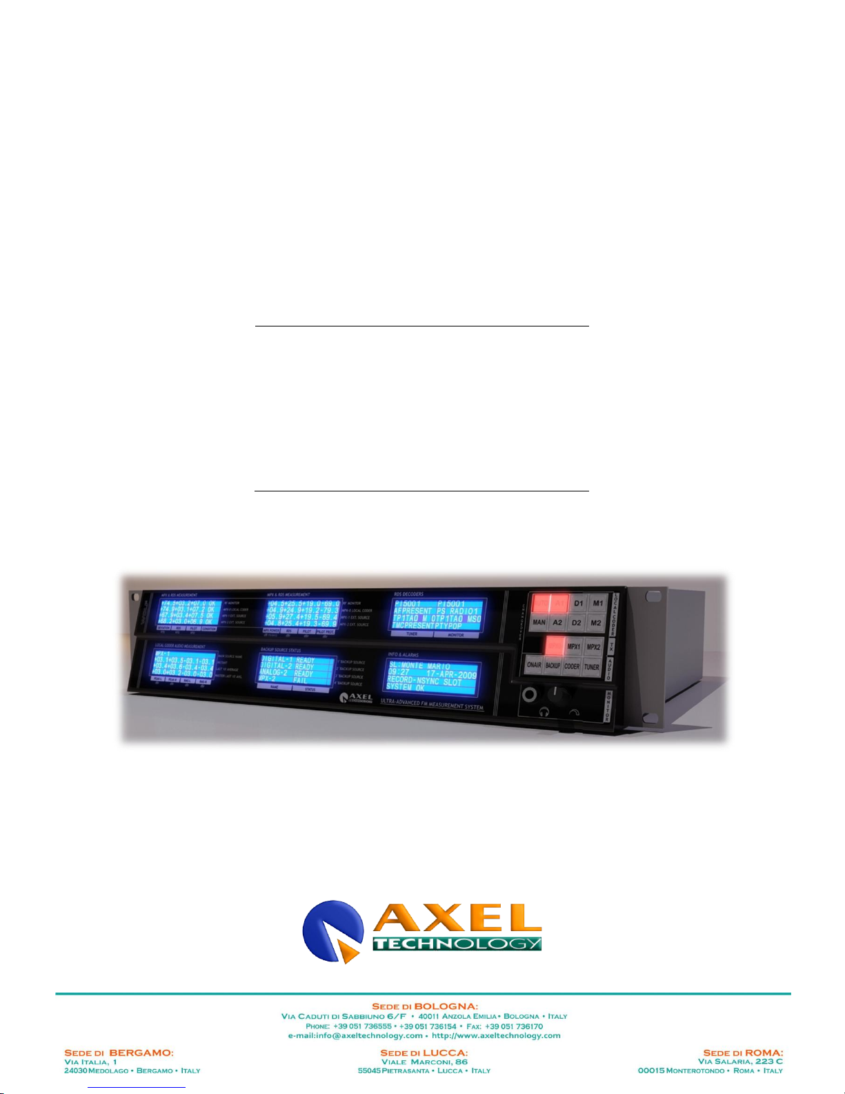
The Wolf is the leading automatic digital measuring and monitoring system for FM networks. It can monitor
analog audio signals, AES/EBU and MPX + RDS or RBDS digital signals and RF signals. It monitors the
quality of the FM signal transmitted in off-air mode and is a powerful and intelligent automatic changeover
device that works between all inputs. It filters all RDS units and - using a local coder - it regenerates a UECP
stream for other coders, as well as managing alarms, and its switching policy is user-settable. It is
combinable with WOLF networks for comparative measurements and automatic tests on the network, with
on-air mode option. Wolf features the following inputs: 2 analog audio, 2 AES/EBU audio, MPX 3, 1 Tuner.
Outputs featured are: 2 analog audio and 2 AES/EBU audio. It includes: 2 quality MPX decoders, 4 MPX
detectors, 3 RS232 ports, 2 RDS decoders, 4 GPIO interfaces and 4 relays. All contained in a single device,
the WOLF
Summing up, the WOLF offers:
Dual stereo analog audio input with bandwidth 20Hz - 20Khz.
Dual AES/EBU digital audio input with sampling frequency 44.1kHz to 96kHz.
Dual MPX input with bandwidth up to 59Khz.
Dual stereo analog audio output with bandwidth 20Hz -20Khz.
AES/EBU digital stereo output with bandwidth 20kHz (and sampling frequency 44.1kHz to 96kHz).
Digital Stereo MPX decoder.
Built-in FM tuner.
Built-in RDS decoder
Input for external tuner (for use of a higher quality FM receiver than the built-in one).
Ethernet interface with web server, SNMP agent and UECP connection via LAN, UECP connection
via SNMP and TFTP support for remote programming.
Dual decoupled RS232 serial protocol for UECP protocol, with UECP channel generating option
Monodirectional operation from a TCP/IP connection, or SNMP to propagate the UECP channel to
other devices in the station.
General purpose interface with 8 decoupled inputs
General purpose interface with 8 decoupled outputs
General purpose interface with 4 SPDT relays
Optional Breakout Box with transformer decoupled analog audio inputs, inputs/output hardware
bypass function, inputs and outputs on XLR balanced line connector.
Optional Breakout Box with transformer decoupled AES/EBU digital audio inputs and outputs,
inputs/output hardware bypass function, inputs and outputs on XLR balanced line connector.
External MPX changeover module (optional) for automatic MPX signal switching.
Measurement module for RMS and Audio signal peak.
2 measurement modules for RMS and signal peak and ITU B412 power on MPX signals.
UECP mixer module and UECP command sequencer with annual programming.

SAFETY WARNINGS / ISTRUZIONI PER LA SICUREZZA
Axel Technology |
3
1 SAFETY WARNINGS / ISTRUZIONI PER LA SICUREZZA
SAFETY WARNINGS
CONSIGNES DE SÉCURITÉ IMPORTANTES
ISTRUZIONI IMPORTANTI PER LA SICUREZZA
WICHTIGE SICHERHEITSHINWEISE
INSTRUCCIONES IMPORTANTES DE SEGURIDAD
(Rel. 1.3)
1.1 FOREWORD
For your own safety and to avoid invalidation of the warranty all text marked with these Warning Symbols
should be read carefully.
Information in this manual is subject to change without notice and does not represent a commitment on the part of the
vendor.
The manufacturer shall not be liable for any loss or damage whatsoever arising from the use of information or any error
contained in this manual, or through any mis-operation or fault in hardware contained in the product.
It is recommended that all maintenance and service on the product should be carried out by the manufacturer or its
authorised agents. The manufacturer cannot accept any liability whatsoever for any loss or damage caused by service,
maintenance or repair by unauthorised personnel.

SAFETY WARNINGS
Axel Technology |
4
2 SAFETY WARNINGS
The installation and servicing instructions in this manual are for use by qualified personnel only.
-
Read All Instructions. All safety and operating instructions must be read before operating the product. They also
must be retained for future reference, as it contains a number of useful hints for determining the best combination of
equipment settings for Yr particular application.
-
Heed All Warnings. All warnings on the product and those listed in the operating instructions must be adhered to.
-
Heat. This product must be situated away from any heat sources such as radiators or other products (including
power amplifiers or transmitters) that produce heat.
-
Power Sources. This product must be operated from the type of power source indicated on the marking label and in
the installation instructions. If you are not sure of the type of power supplied to your facility, consult your local power
company. Make sure the AC main voltage corresponds to that indicated in the technical specifications. If a different
voltage (ex. 110/115 VAC) is available, open the equipment closure and set the voltage switch on the main supply
circuit, located behind the AC socket
-
Power Cord Protection. Power supply cords must be routed so that they are not likely to be walked on nor pinched
by items placed upon or against them. Pay particular attention to the cords at AC wall plugs and convenience
receptacles, and at the point where the cord plugs into the product
-
Use only with a cart, stand, tripod, bracket, or table specified by the manufacturer, or sold with the apparatus. When
a cart is used, use caution when moving the cart/apparatus combination to avoid injury from tip-over.
-
Lightning. For added protection for this product during a lightning storm, or when it is left unattended and unused for
long periods of time, unplug it from the AC wall outlet and the audio connections. This will prevent damage to the
product due to lightning and power line surges
-
Installation. Configuration and installation should only be carried out by a competent installation engineer
-
Cabling. Using high quality wires, well protected. Make sure the cable integrity.
This symbol alerts you to the presence of dangerous voltage inside the closure –voltage which
may be sufficient to constitute a risk of shock. Do not perform any servicing other than that
contained in the operating instructions. Refer all servicing to qualified personnel
The exclamation point within an equilateral triangle is intended to alert the user to the presence of
important operating and maintenance (servicing) instructions in the literature accompanying the
appliance.
Do not change the voltage setting or replace the mains fuse without first turning the unit off
and unplugging the mains cord
Make sure the AC main voltage corresponds to that indicated in the technical specifications.
THIS APPARATUS MUST BE EARTHED !
To avoid risk of fire use the correct value fuse, as indicated on the label stuck on the right
side of the unit.
This apparatus uses a single pole mains switch and does therefore not separate the unit
completely from the mains power. To completely separate from mains power (f.i. in the event
of danger) unplug mains power cord. As the MAINS plug is the disconnect device, the
disconnect device shall remain readily operable.

CONSIGNES DE SÉCURITÉ IMPORTANTES
Axel Technology |
5
3 CONSIGNES DE SÉCURITÉ IMPORTANTES
-
Lire ces consignes
-
Conserver ces consignes
-
Observer tous les avertissements
-
Suivre toutes les consignes
-
Ne pas utiliser cet appareil à proximité de l’eau
-
Ne pas obstruer les ouvertures de ventilation. Installer en respectant les consignes du fabricant
-
Ne pas installer à proximité d'une source de chaleur telle qu'un radiateur, une bouche de chaleur, un poêle ou
d'autres appareils (dont les amplificateurs) produisant de la chaleur.
-
Ne pas annuler la sécurité de la fiche de terre, la troisième branche est destinée à la sécurité. Si la fiche fournie
ne s'adapte pas à la prise électrique, demander à un électricien de remplacer la prise hors normes.
-
Protéger le cordon d'alimentation afin que personne ne marche dessus et que rien ne le pince, en particulier aux
fiches, aux prises de courant et au point de sortie de l‟appareil
-
Utiliser uniquement les accessoires spécifiés par le fabricant
-
Utiliser uniquement avec un chariot, un support ou une table spécifié par le fabricant ou vendu avec l‟appareil. Si
un chariot est utilisé, déplacer l‟ensemble chariot–appareil avec précaution afin de ne pas le renverser, ce qui
pourrait entraîner des blessures
-
Débrancher l’appareil pendant les orages ou quand il ne sera pas utilisé pendant longtemps.
-
Confier toute réparation à du personnel qualifié. Des réparations sont nécessaires si l‟appareil est endommagé
d‟une façon quelconque, par exemple: cordon ou prise d‟alimentation endommagé, liquide renversé ou objet tombé à
l‟intérieur de l‟appareil, exposition de l‟appareil à la pluie ou à l‟humidité, appareil qui ne marche pas normalement ou
que l‟on a fait tomber.
-
NE PAS exposer cet appareil aux égouttures et aux éclaboussements. Ne pas poser des objets contenant de
l'eau, comme des vases, sur l'appareil
Ce symbole indique la présence d'une tension dangereuse dans l'appareil constituant un risque de
choc électrique.
Ce symbole indique que la documentation fournie avec l'appareil contient des instructions
d'utilisation et d'entretien importantes.
Avant de modifier le commutateur de changement de tension ou replacer le fusible il faut
débrancher l’appareil de la prise électrique. Pendant son usage, l’appareil doit etre branchee à la
prise de terre
Utiliser le fusible principal AC avec le valeur qui est indiquée sur l'étiquette collée sur le coffret.
Assurez-vous que la tension principale AC correspond à celle indiquée dans les spécifications
techniques.
L’interrupteur d’alimentation interrompt un pôle du réseau d’alimentation excepté le conducteur
de terre de protection. En cas de danger, debrancher le cordon d'alimentation. Parce que la prise
du réseau de alimentation est utilisée comme dispositif de déconnexion, ce dispositif doit
demeuré aisément accessible

ISTRUZIONI IMPORTANTI PER LA SICUREZZA
Axel Technology |
6
4 ISTRUZIONI IMPORTANTI PER LA SICUREZZA
-
Leggere le presenti istruzioni
-
Conservare queste istruzioni
-
Osservare tutte le avvertenze
-
Seguire scrupolosamente tutte le istruzioni
-
Non usare questo apparecchio in prossimità di acqua
-
Non ostruire alcuna apertura per il raffreddamento. Installare l‟apparecchio seguendo le istruzioni
-
Non installare l'apparecchio accanto a fonti di calore quali radiatori, aperture per l'afflusso di aria calda, forni o
altri apparecchi (amplificatori inclusi) che generino calore
-
Non rimuovere il terminale di connessione a terra sul cordone di alimentazione: esso ha lo scopo di tutelare
l‟incolumità dell‟utilizzatore. Se la spina in dotazione non si adatta alla presa di corrente, rivolgersi ad un elettricista
per far eseguire le modifiche necessarie.
-
Evitare di calpestare il cavo di alimentazione o di comprimerlo, specialmente in corrispondenza della spina e del
punto di inserzione sull‟apparato.
-
Utilizzare solo dispositivi di collegamento e gli accessori specificati dal produttore.
-
Utilizzare l’apparecchio solo con un carrello, un sostegno, una staffa o un tavolo di tipo specificato dal produttore o
venduto insieme all‟apparecchio. Se si utilizza un carrello, fare attenzione negli spostamenti per evitare infortuni
causati da ribaltamenti del carrello stesso.
-
Scollegare l’apparecchio dalla presa di corrente durante i temporali o quando inutilizzato a lungo
-
Per qualsiasi intervento, rivolgersi a personale di assistenza qualificato. È‟ necessario intervenire sull‟apparecchio
ogniqualvolta si verificano danneggiamenti di qualsiasi natura. Ad esempio, la spina o il cavo di alimentazione sono
danneggiati, è entrato liquido nell‟apparecchio o sono caduti oggetti su di esso, l‟apparecchio è stato esposto alla
pioggia o all‟umidità, non funziona normalmente o è caduto.
-
Non esporre a sgocciolamenti o spruzzi. Non appoggiare sull'apparecchio oggetti pieni di liquidi, ad esempio vasi
da fiori.
Questo simbolo indica la presenza di alta tensione all'interno dell'apparecchio, che comporta rischi di
scossa elettrica.
Questo simbolo indica la presenza di istruzioni importanti per l'uso e la manutenzione nella
documentazione in dotazione all'apparecchio.
Non sostituire il fusibile o cambiare la tensione di alimentazione senza aver prima scollegato il
cordone di alimentazione. L’APPARATO DEVE ESSERE CONNESSO A TERRA.
Sostituire il fusibile generale con uno di identico valore, come indicato sulla etichetta applicata
sul mobile dell’apparato
Assicurarsi che la tensione di rete corrisponda a quella per la quale è configurato
l’apparecchio
Questo apparato utilizza un interruttore di alimentazione di tipo unipolare e l’isolamento dalla
rete elettrica non è pertanto completo. Per ottenere un isolamento totale (ad esempio in caso di
pericolo), scollegare il cordone di alimentazione. Inoltre, poichè la spina di alimentazione è
utilizzata come dispositivo di sezionamento, essa deve restare facilmente raggiungibile

WICHTIGE SICHERHEITSHINWEISE
Axel Technology |
7
5 WICHTIGE SICHERHEITSHINWEISE
-
Diese Hinweise LESEN
-
Diese Hinweise AUFHEBEN
-
Alle Warnhinweise BEACHTEN
-
Alle Anweisungen BEFOLGEN
-
Dieses Gerät NICHT in der Nähe von Wasser verwenden
-
KEINE Lüftungsöffnungen verdecken. Gemäß den Anweisungen des Herstellers einbauen
-
Nicht in der Nähe von Wärmequellen, wie Heizkörpern, Raumheizungen, Herden oder anderen Geräten
(einschließlich Verstärkern) installieren, die Wärme erzeugen
-
Die Schutzfunktion des Schukosteckers NICHT umgehen. Bei Steckern für die USA gibt es polarisierte Stecker,
bei denen ein Leiter breiter als der andere ist; US-Stecker mit Erdung verfügen über einen dritten Schutzleiter. Bei
diesen Steckerausführungen dient der breitere Leiter bzw. der Schutzleiter Ihrer Sicherheit. Wenn der mitgelieferte
Stecker nicht in die Steckdose passt, einen Elektriker mit dem Austauschen der veralteten Steckdose beauftragen
-
VERHINDERN, dass das Netzkabel gequetscht oder darauf getreten wird, insbesondere im Bereich der Stecker,
Netzsteckdosen und an der Austrittsstelle vom Gerät
-
NUR das vom Hersteller angegebene Zubehör und entsprechende Zusatzgeräte verwenden.
-
NUR in Verbindung mit einem vom Hersteller angegebenen oder mit dem Gerät verkauften Transportwagen, Stand,
Stativ, Träger oder Tisch verwenden. Wenn ein Transportwagen verwendet wird, beim Verschieben der
Transportwagen-Geräte- Einheit vorsichtig vorgehen, um Verletzungen durch Umkippen
-
Das Netzkabel dieses Geräts während Gewittern oder bei längeren Stillstandszeiten aus der Steckdose
ABZIEHEN.
-
Alle Reparatur- und Wartungsarbeiten von qualifiziertem Kundendienstpersonal DURCHFÜHREN LASSEN.
Kundendienst ist erforderlich, wenn das Gerät auf irgendwelche Weise beschädigt wurde, z.B. wenn das Netzkabel
oder der Netzstecker beschädigt wurden, wenn Flüssigkeiten in das Gerät verschüttet wurden oder Fremdkörper
hineinfielen, wenn das Gerät Regen oder Feuchtigkeit ausgesetzt war, nicht normal funktioniert oder fallen gelassen
wurde.
-
Dieses Gerät vor Tropf- und Spritzwasser SCHÜTZEN. KEINE mit Wasser gefüllten Gegenstände wie zum
Beispiel Vasen auf das Gerät STELLEN.
Dieses Symbol zeigt an, dass gefährliche Spannungswerte, die ein Stromschlagrisiko darstellen,
innerhalb dieses Geräts auftreten.
Dieses Symbol zeigt an, dass das diesem Gerät beiliegende Handbuch wichtige Betriebs- und
Wartungsanweisungen enthält.
Vor Änderung der Netzspannung oder Sicherungswechsel Netzkabel trennen.
Das Gerät muss für den Betrieb geerdet werden.
Hauptsicherung nur mit einer gleichwertigen austauschen
(s. entsprechende Etikette).
Vor Einschalten Netzspannungseinstellung am Gerät überprüfen bzw. anpassen.
Inpoliger Netzschalter. In Notfälle oder für Wartungsarbeiten Netzkabel trennen. Der Netzstecker
fungiert auch als Trennelement muss deshalb zugänglich bleiben

INSTRUCCIONES IMPORTANTES DE SEGURIDAD
Axel Technology |
8
6 INSTRUCCIONES IMPORTANTES DE SEGURIDAD
-
LEA estas instrucciones
-
CONSERVE estas instrucciones
-
PRESTE ATENCION a todas las advertencias.
-
SIGA todas las instrucciones
-
NO utilice este aparato cerca del agua
-
NO obstruya ninguna de las aberturas de ventilación. Instálese según lo indicado en las instrucciones del
fabricante
-
No instale el aparato cerca de fuentes de calor tales como radiadores, registros de calefacción, estufas u otros
aparatos (incluyendo amplificadores) que produzcan calor
-
NO anule la función de seguridad del enchufe polarizado o con clavija de puesta a tierra. Un enchufe polarizado
tiene dos patas, una más ancha que la otra. Un enchufe con puesta a tierra tiene dos patas y una tercera clavija con
puesta a tierra. La pata más ancha o la tercera clavija se proporciona para su seguridad. Si el toma corriente no es
del tipo apropiado para el enchufe, consulte a un electricista para que sustituya el toma corriente de estilo anticuado
-
PROTEJA el cable eléctrico para evitar que personas lo pisen o estrujen, particularmente en sus enchufes, en los
toma corrientes y en el punto en el cual sale del aparato
-
UTILICE únicamente los accesorios especificados por el fabricante
-
UTILICESE únicamente con un carro, pedestal, escuadra o mesa del tipo especificado por el fabricante o vendido
con el aparato. Si se usa un carro, el mismo debe moverse con sumo cuidado para evitar que se vuelque con el
aparato
-
DESENCHUFE el aparato durante las tormentas eléctricas, o si no va a ser utilizado por un lapso prolongado.
-
TODA reparación debe ser llevada a cabo por técnicos calificados. El aparato requiere reparación si ha sufrido
cualquier tipo de daño, incluyendo los daños al cordón o enchufe eléctrico, si se derrama líquido sobre el aparato o
si caen objetos en su interior, si ha sido expuesto a la lluvia o la humedad, si no funciona de modo normal, o si se ha
caído.
-
NO exponga este aparato a chorros o salpicaduras de líquidos. NO coloque objetos llenos con líquido, tales como
floreros, sobre el aparato .
Este símbolo indica que la unidad contiene niveles de voltaje peligrosos que representan un riesgo
de choques eléctricos.
Este símbolo indica que la literatura que acompaña a esta unidad contiene instrucciones importantes
de funcionamiento y mantenimiento.
Antes de cambiar la alimentacion de voltaje o de cambiar el fusible, desconecte el cable de
alimentacion. Para reducir el riesgo de descargas electricas, esta unidad debe ser conectada a
tierra.
Remplaze el fusible con lo mismo, que corresponde a lo indicado en el panel del equipo.
Antes de encender, controlar que la linea de alimentacion de voltaje corresponda a la indicada
El interruptor de alimentación es unipolar. En el caso de peligro, desconecte el cable de
alimentación. Porque la clavija de conexion a red sirve por la desconection de la unidad, la
clavija debe ser ubicada en proximidad de la unidad

UNPACKING AND INSPECTION
Axel Technology |
9
7 UNPACKING AND INSPECTION
Your equipment was packed carefully at the factory in a container designed to protect the unit during shipment.
Nevertheless, we recommend making a careful inspection of the shipping carton and the contents for any signs of
physical damage.
Damage & Claims
If damage is evident, do not discard the container or packing material. Contact your carrier immediately to file a claim for
damages. Customarily, the carrier requires you, the consignee, to make all damage claims. It will be helpful to retain the
shipping documents and the waybill number.
Save all packing materials! If You should ever have to ship the unti (e.g. for servicing), it is best to ship it in the
original carton with its packing materials because both the carton and packing material have been carefully
designed to protect the unit.
Under normal conditions no user maintenance or calibration are required. Internal links and preset controls may be set to
configure the unit during installation. Any service work required should be carried out by qualified service
personnel only.
We are able to offer further product support through our worldwide network of approved dealers and service agents.
To help us provide the most efficient service please would you keep a record of the unit serial
number, and date and place of purchase to be quoted in any communication regarding this
product.
The actual equipment Serial Number is indicated on the silver label stuck on the rear panel of the equipment closure.
Tools And Equipment Needed
Only standard technician’s tools are required to install this equipment.

FIRST INSTALLATION RECOMMENDATIONS
Axel Technology |
10
8 FIRST INSTALLATION RECOMMENDATIONS
8.1 POWER SUPPLY CABLE
A power supply cable of approx. 2 mt length is supplied with the device, which has a moulded IEC plug attached –this is
a legal requirement.
The type of plug for the power supply depends on the country in which it is delivered.
If for any reason, you need to use this appliance with a different plug, you should use the following wiring guidelines in
replacing the exsisting plug with the new one:
Earth
Green, or green and yellow
Neutral (N)
Blue
Live (L)
Brown
Supply cables should be laid in such a manner that one does not step or walk on them. They should not be squashed by
any objects.
THIS EQUIPMENT MUST BE EARTHED.
The chassis is always connected to mains earth to ensure your safety: check your mains wiring and earthing before
switching on.
8.2 AC MAINS VOLTAGE SETTING (230 V / 115 V)
BE SURE THAT THE UNIT IS SET TO THE CORRECT MAINS/LINE VOLTAGE FOR YOUR
COUNTRY BEFORE PLUGGING IT INTO THE WALL OUTLET !
The actual Mains voltage is indicated on the label stuck on the equipment closure. Should the type of power at the
operation location not be known, please contact your dealer or electricity company.
If, for some reason, the unit is to be operated at a mains input voltage which is different to that as supplied, you need to
switch the voltage selector on the right side of the unit. You also need to replace the AC main fuse, according to
information provided on the external label or on the Technical Specifications table at the end of this user manual.
CAUTION: TO REDUCE THE RISK OF ELECTRICAL SHOCK, ALWAYS DISCONNECT THE AC
MAINS CABLE BEFORE ALTERING THE CHANGE-OVER SWITCH. NO USER SERVICEABLE
PARTS INSIDE. REFER SERVICING TO QUALIFIED SERVICE PERSONNEL.

FIRST INSTALLATION RECOMMENDATIONS
Axel Technology |
11
8.3 FUSE REPLACEMENT
The power supply socket has an integral fuse drawer containing the AC power fuse and a spare, both of the same value.
BEFORE REPLACING THE POWER FUSE, MAKE SURE YOU HAVE THE RIGHT TYPE OF FUSE FOR
THE VOLTAGE TO BE PROTECTED.
USING WRONG FUSE TYPE WILL RESULT IN INSUFFICIENT PROTECTION.
Make sure that the power is switched off and the power cable is disconnected from the equipment.
a. Open the fuse drawer using a small blade screwdriver.
b. Replace the fuse located at the internal position
c. Push the fuse socket back into the original position (a.)
Perform the set-up under static control conditions. Static charges are likely to completely destroy one or
more of the CMOS semiconductors employed in the unit. Static damage will not be covered under
warranty.
Basic damage prevention consists of minimizing generation, discharging any accumulated static charge
on your body and preventing that discharge from being sent to or through any electronic component.
Uninsulated dangerous voltage are inside the enclosure, voltage that may be sufficient to constitute a
risk of shock.
Always disconnect to AC Mains before removing the top cover

INTRODUCTION
Axel Technology |
12
8.4 PROTECTION AGAINST LIGHTNING
Should the device be put out of action due to being struck by lightning or excess voltage, disconnect it
from the power supply without delay. Do not reconnect until the device has been checked. If in doubt
contact the technical support service.
Make sure there is suitable lightning protection to protect the device.
Alternatively you should disconnect all connectors from the device during a storm or when the device
is going to be unsupervised or not used for a longer period of time.
These measures will protect against damage by lightning or excess voltage.
8.5 VENTILATION
The equipment will operate as a free-standing unit without requiring any special cooling arrangement.
However, slots and openings in the product are provided for ventilation. They ensure reliable operation of the product,
keeping it from overheating. These openings must not be blocked nor covered during operation.
YOU MUST LEAVE AT A MINIMUM ONE RACK UNIT OF EMPTY SPACE ABOVE THE EQUIPMENT TO ENHANCE
VENTILATION AND TO GET A LONGER EQUIPMENT LIFE.
9 INTRODUCTION
9.1.1 VERSIONS AVAILABLE
CODE
MODEL
DESCRIPTION
A110050008
WOLF
Automatic digital measuring and monitoring system for FM networks, on analog
audio, AES/EBU and MPX/RDS. Automatic changeover between inputs, RDS
filter, alarm management, SNMP, Web server. 2 RU. Combinable with WOLF-
REF for comparative measurements and automatic tests on the network.
RS232/Ethernet port for remote control via PC.
A110050005
WOLF REF
Automatic reference signal generation and measurement system for the WOLF
system. Management of analog audio and AES/EBU outputs GPI control port
alarm management, SNMP, Web server. 1 RU. Combinable with WOLF networks
for comparative measurements and automatic tests on the network.
RS232/Ethernet port for remote control via PC.
9.1.2 OPTIONS AVAILABLE
CODE
OPTION
DESCRIPTION
A110050316
WLF-ADPTA
Wolf Analog Adapter on 8 XLR (2 stereo IN, 2 stereo OUT).
A110050317
WLF-ADPTD
Wolf Ditigal Adapter on 4 XLR (2 AES/EBU IN, 2 AES/EBU OUT).
A110050320
WLF-BBAM
Analog Audio and MPX signal breakout box, HW bypass functions for all
outputs, 19'' 1u rack. Includes 1m Wolf/BB connection cables.
A110050324
WLF-BBD
AES/EBU Audio breakout box, HW bypass functions for the two outputs,
AES/EBU distributor, 6 out., 19'' 1u rack. Includes 1m Wolf/BB connection
cables.

WOLF FUNCTIONAL AND CONNECTION DIAGRAM
Axel Technology |
13
10 WOLF FUNCTIONAL AND CONNECTION DIAGRAM

Axel Technology |
14
10.1 WOLF MEASUREMENTS / CHANGEOVER DIAGRAM

Axel Technology |
15
10.2 WOLF FRONT PANEL
N°
IMAGINE
DESCRIPTION
1
Display for:
“LOCAL CODER AUDIO MEASUREMENT”
2
Display for:
“MPX & RDS MEASUREMENT”
3
Display for:
“BACKUP SOURCE STATUS”
4
Display for:
“MPX & RDS MEASUREMENT”

Axel Technology |
16
5
Display for:
“INFO & ALARMS”
6
Display for:
“RDS DECODERS”
7
8
Monitor module with
7. Headphone socket for monitor - 6.3 mm
jack
8. Output volume dial
9
10
Module for:
9. Listening audio selection
10. Transmitter selection
11
Selection:
LOCAL CODER + CHANGEOVER

Axel Technology |
17
10.3 WOLF REAR PANEL
N°
FIGURE
DESCRIPTION
1
Label with device model and serial number
2
Power supply + fuse unit
3
RS232-1
RS-232 serial port n. 1. For Wolf device control
and monitoring and firmware upgrades
4
RS232-2
RS-232 serial port n.2. For Wolf device control
and monitoring
5
Ethernet
Ethernet port for connection to RJ-45
6
RS232-3
RS-232 serial port n. 3.
7
Vacancy for future implementations

Axel Technology |
18
8
Analog Audio Monitor Output
Analog audio output for the monitor. This output is
available when you select the monitor from the
front panel, via the balanced line male XLR
connector.
9
Opto Relays Interface 2
Isolated opto relay interface for aux. services 2
(see technical appendix for specifications)
10
Opto Relays Interface 1
Isolated opto relay interface for aux. services 1
(see technical appendix for specifications)
11
Relays
Relay interface (see appendix)
12
Digital audio I/O
AES/EBU Digital Audio Input and Output
13
BB MPX Reserve
Connection socket for MPX Breakout Box
14
MPX-2
Secondary MPX input (Backup)
15
MPX-1
Primary MPX input (Main)
16
MPX-0
MPX input from Local Coder (MPX0)
17
RF MONITOR
MONITOR RF input from Transmitter Test RF
18
BB Analog Reserve
Breakout box for analog Backup inputs
19
Analog audio I/O
Socket for Analog Inputs and Outputs
20
Air intake slits Fans inside the WOLF ensure
forced air circulation

WOLF CONNECTIONS (BREAKOUT BOXES)
Axel Technology |
19
11 WOLF CONNECTIONS (BREAKOUT BOXES)
To facilitate connections to and from Wolf, there are two different optional connection boxes available that simplify
connections. Thanks to these expansion panels, the connections can be brought to the front or rear of the rack,
depending on the technical requirements of the installation in question.
The Wolf handles analog and digital signals. More specifically, there are two different Breakout Boxes available, a
digital-only version (WLF-BBD) and a hybrid version, featuring inputs and outputs for analogue and mpx signals (WLF-
BBAM)
In the figure below, showing the Wolf Digital Breakout Box (WLF-BBD, there are two separate inputs (IN C and IN D) and
the relative outputs (OUT C and OUT D), in addition to the further outputs (OUT 1, OUT 2, OUT 3, OUT 4). These
outputs can be fully configured as required; the default jumper settings inside the Breakout Box are such that these
always reproduce OUTPUT C. All inputs and outputs are transformer de-coupled, with a characteristic impedance of 110
ohms.
In addition to the individual in/out connections, the BB also allows the device to have active independent service outputs
assignable to inputs/outputs. This is to facilitate installation. For the Breakout Box connection details and operating
parameters, please refer to the Technical Appendix at the end of the manual.
The figure below shows the Wolf Analog and MPX Breakout Box (WLF-BBAM).

WHAT IS THE WOLF NETWORK AND WHAT IS IT FOR?
Axel Technology |
20
12 WHAT IS THE WOLF NETWORK AND WHAT IS IT FOR?
The WOLF is a powerful, multi-functional FM station monitor . The device is designed to monitor audio signals, including
analog signals, digital signals, and MPX signals (with or without RDS), as well as free air signals, in the FM bandwidth
(87.5 - 108.0 MHz). The results of the measurements, whether performed on audio signals, MPX signals or on free air
signals, are directly accessible as HTML pages, using the built-in Web Server, or the dedicated PC monitoring software.
The results of the measurements carried out can also be compared with a grid of preset values, with the generation of
appropriate alarms in the event of out-of-range values. The Wolf supports the following protocols: UECP , SNMP, HTTP
and TFTP.
13 THE MAIN CONCEPT OF THE WOLF NETWORK DEVICE
The ways in which to connect the Wolf are many and varied. They differ depending on the needs of the broadcasters
using the device on their network. The versatility and, above all, the number of functions, operations, and facilities of this
equipment mean it can be put to a wide range of uses. One of the fundamental concepts of the Wolf, one of its most
conventional intended uses and - above all - one of the functions for which the device was conceived, is the ability to
manage its powerful internal changeover function, according to the precise meter featured. The Wolf‟s internal
changeover function allows the device to broadcast the „best‟ audio source, according to the reference parameters
configured internally.
14 AUTOMATIC MODE
In automatic mode, the Wolf automatically runs a series of pre-set measurements on audio signals and MPX, RDS and
antenna signals, and records the results in its log file. The machine can also compare the measurements against
reference values or ranges (called Thresholds) preset by the operator, or other reference data. This mode is generally
the standard operating mode. In this mode you cannot change any system configuration parameter. When the Wolf is
set to 'Auto' or is carrying out on-line measurements, other measurements are carried out at the same time, including:
Pilot Level, RDS level, peak deviation and power (as required by standard ITU-R BS412) on the two signals marked
MPX-1 and MPX-2. Depending on the how the device is configured, these will correspond to either the external Base
Bandwidth MPX-1 and MPX-2 inputs, the built-in tuner output, or the output of any external tuner that may be in use.
One RDS decoder stage, meanwhile, can be applied either to one of the two signals MPX-1 or MPX-2 or directly to the
signal outputted by the built-in tuner or the external tuner.
In addition, the Wolf decoder features a built-in digital stereo decoder which can also be applied to the internal MPX-1 or
MPX-2 signal. The output of the stereo decoder is measured using an RMS meter. The Wolf also measures stereo audio
input signals, both analogue and digital. The measurements concern the instantaneous peak level or the average peak
levels over a given period and also the instantaneous RMS level or the average level over a given period.
15 MANUAL MODE
When in manual mode, the parameters can be altered, but the device‟s automatic measuring and monitoring operations
will be suspended. In manual mode, a measurement can effectively be selected and the results viewed using the device
as a normal workbench tool.
The Wolf acts as a peak meter and an RMS meter (both stereo), which can be applied to either analog or
digital audio signals, as well as external MPX-1 and MPX-2 signals, whether at the output of the tuners or
of the MPX stereo decoder, which can, in turn, be applied to various signals. When the signal measured is
a mono signal (as in the case of an MPX), a 'Mono to Stereo' conversion module is automatically added to
the chain, to standardise it with the measurement of stereo audio signals. Note that the type of
measurement to be carried out, i.e. the pilot level, the pilot distortion, the RDS level, etc. is set via the
particular filter selected manually from those available in the filter selection menu page. All measurements
are always expressed as dBr (dB relative) and refer to the reference level selected for each input via the
Reference menu (see the Reference stages applied to each input, which actually represent the Fixed gain value
applied to that particular input). The Web Server screen page shows the Manual control settings.
16 LOCAL/REMOTE MODE
When it is in local mode, the Wolf does not accept operating commands from remote devices. All UECP / SNMP / HTTP
activation commands are therefore masked graphically via the software. TFTP commands are always accepted, as they
are considered globally configured macro-operations. In this mode it is assumed that the local operator has total control
of the device. In remote mode (normal operating condition), all commands are accepted, with all the complications for an
operator inherent to shared parameters in the event of local navigation.
Table of contents