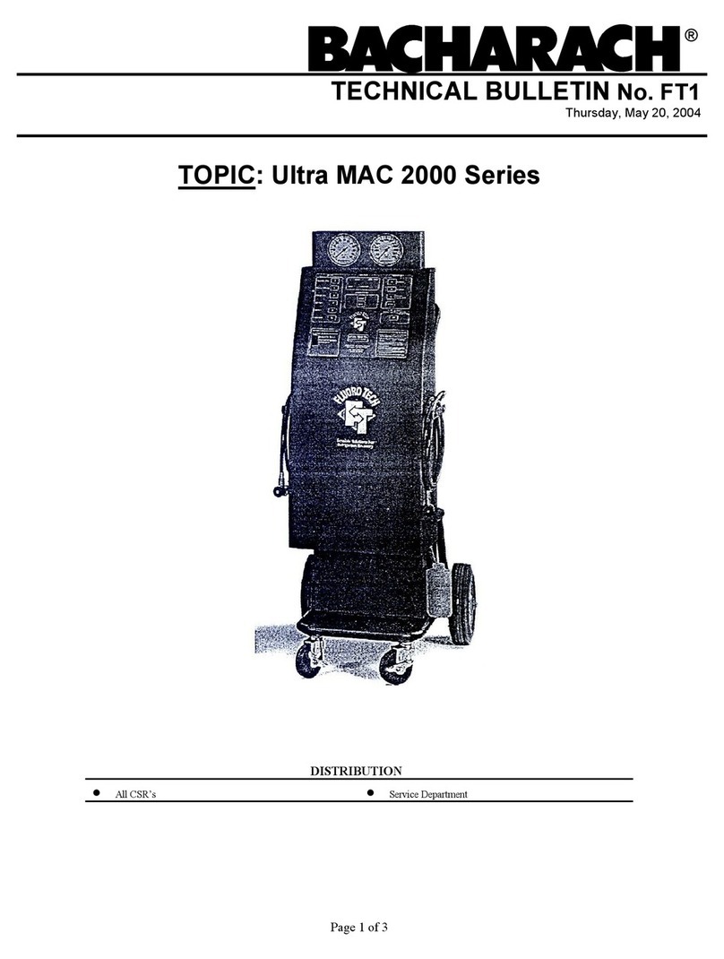
Bacharach 2072-0400 Manual

Instruction 2072-0400
Operation & Maintenance
Rev. 0 – March 2002
Product Leadership • Training • Service • Reliability

WARRANTY
Bacharach, Inc. warrants to Buyer that at the time of delivery this Product will be free from defects in material
and manufacture and will conform substantially to Bacharach Inc.’s applicable specifications. Bacharach’s
liability and Buyer’s remedy under this warranty are limited to the repair or replacement, at Bacharach’s
option, of this Product or parts thereof returned to Seller at the factory of manufacture and shown to
Bacharach Inc.’s reasonable satisfaction to have been defective; provided that written notice of the defect shall
have been given by Buyer to Bacharach Inc. within one (1) year after the date of delivery of this Product by
Bacharach, Inc.
Bacharach, Inc. warrants to Buyer that it will convey good title to this Product. Bacharach’s liability and
Buyer’s remedy under this warranty of title are limited to the removal of any title defects or, at the election of
Bacharach, to the replacement of this Product or parts thereof that are defective in title.
THE FOREGOING WARRANTIES ARE EXCLUSIVE AND ARE GIVEN AND ACCEPTED IN LIEU OF (I)
ANY AND ALL OTHER WARRANTIES, EXPRESS OR IMPLIED, INCLUDING WITHOUT LIMITATION
THE IMPLIED WARRANTIES OF MERCHANTABILITY AND FITNESS FOR A PARTICULAR PURPOSE:
AND (II) ANY OBLIGATION, LIABILITY, RIGHT, CLAIM OR REMEDY IN CONTRACT OR TORT,
WHETHER OR NOT ARISING FROM BACHARACH’S NEGLIGENCE, ACTUAL OR IMPLIED. The remedies
of the Buyer shall be limited to those provided herein to the exclusion of any and all other remedies including,
without limitation incidental or consequential damages. No agreement varying or extending the foregoing
warranties, remedies or this limitation will be binding upon Bacharach, Inc. unless in writing, signed by a duly
authorized officer of Bacharach.
Note: The Filter Drier and Refrigerant Identifier Filter are considered consumable items, and are therefore not
covered under the terms of this warranty.
Register Your Warranty by Visiting
www.bacharach-inc.com
Notice:
Product improvements and enhancements are continuous; therefore the specifications and information
contained in this document may change without notice.
Bacharach, Inc. shall not be liable for errors contained herein or for incidental or consequential damages in
connection with the furnishing, performance, or use of this material.
No part of this document may be photocopied, reproduced, or translated to another language without the prior
written consent of Bacharach, Inc.
Copyright © 2002, Bacharach, Inc., all rights reserved.
BACHARACH®is a registered trademark of Bacharach, Inc. All other trademarks, trade names,
service marks and logos referenced herein belong to their respective owners.
A Instruction 2072-0400

Contents MAC 2000
Table of Contents
1Introduction .......................................................................................................... 1
1.1 Glossary of Terms.....................................................................................................2
1.2 General Operating Guidelines.................................................................................2
1.3 Component Location and Description .....................................................................3
1.4 Using the Function Keys..........................................................................................7
1.5 Using the Up/Down, Increase, Decrease, and Back/Forward Arrow Keys............7
2Initial Set-Up ......................................................................................................... 9
2.1 Initial Set-Up Instructions ......................................................................................9
2.2 Checking Vehicles for Possible Contaminated Systems......................................11
2.3 External Source Tank Testing...............................................................................11
3Operation ............................................................................................................. 13
3.1 MAC2000 Operational Overview...........................................................................13
3.2 Diagnosing A/C System Operation Using the Snap-Shot Mode .........................15
3.3 Recovery Mode........................................................................................................18
3.4 Vacuum Mode (Evacuation)...................................................................................19
3.5 Charge Mode...........................................................................................................20
3.6 System Flush Mode (Oil Flush) .............................................................................22
3.7 Refrigerant Management System .........................................................................24
3.8 Internal Tank Manual Refill .................................................................................25
3.9 System Set Up ........................................................................................................26
3.10 Identify Refrigerant ...............................................................................................26
3.11 Check Internal Tank for Air ..................................................................................27
4Maintenance ........................................................................................................ 29
4.1 Changing the Filter Drier......................................................................................29
4.2 Replacing the External Source Tank ....................................................................30
4.3 Replacing the Printer Paper ..................................................................................31
4.4 Replacing the Refrigerant Identifier Filter...........................................................32
5Parts and Service ............................................................................................... 33
5.1 Parts........................................................................................................................33
5.2 Service Centers.......................................................................................................34
Instruction 2072-0400 i

MAC2000
SERIES: MAC2000 Refrigerant: 134a
KENT MOORE: J-055000
Air Conditioning and Refrigerant
Service Solution
WARNING
PRESSURIZED TANK CONTAINS LIQUID REFRIGERANT. OVERFILLING OF THE TANK MAY CAUSE
VIOLENT EXPLOSION AND POSSIBLE INJURY OR DEATH. Safety devices require the use of only authorized
refillable tanks. Refer to the instruction manual for tank specifications and ordering information. Do not recover
refrigerants in a non-refillable storage container! Regulations require refrigerant to be transported only in
specifically authorized containers.
ALL HOSES MAY CONTAIN LIQUID REFRIGERANT UNDER PRESSURE. Contact with refrigerant may cause
injury. Wear proper protective equipment, including safety goggles. Disconnect hoses with extreme caution.
HIGH VOLTAGE ELECTRICITY INSIDE PANELS. RISK OF ELECTRICAL SHOCK. Disconnect power before
service unit. Refer to the instruction manual.
TO REDUCE RISK OF FIRE,avoid the use of an extension cord. The extension cord may
overheat. If you must use an extension cord, the cord must be 14 AWG minimum and as short as possible. Do not
use this equipment in the vicinity of spilled or open containers of gasoline or other flammable substances.
Use this equipment in locations with mechanical ventilation that provides at least four air changes per hour or
locate the equipment at least 18 inches above the floor.
Make certain that all safety devices are functioning properly before operating the unit. Before operating, read and
follow the instructions and warnings in the manual.
CAUTION: SHOULD BE OPERATED BY QUALIFIED PERSONNEL. Technician must be familiar with air
conditioning and refrigeration systems, refrigerants and the dangers of pressurized components.
Use with the R-134a refrigerant only. This equipment is not designed for any other purpose other than recovering,
recycling and charging refrigerants. Do not mix refrigerant types.
OPERATING NOTES
Change the filter-drier when the display shows Change Filter message. Follow the instructions for the changeover.
At temperatures exceeding 120 °F / °C, wait 10 minutes between recovery jobs.
R-134a WARNINGS!
Use the MAC2000 unit only with R-134a refrigerants. Cross-contamination with other refrigerant types will cause
severe damage to the A/C systems and to service tools and equipment. Do not mix refrigerant types through a
system or in the same container.
Avoid breathing A/C refrigerant and lubricant vapor mist. Exposure may irritate eyes, nose and throat. To remove
R-134a from the system, use service equipment certified to meet the requirements of SAE-J2210 (R-134a
recycling equipment). If accidental system discharge occurs, ventilate work area before resuming service.
HFC-134a service equipment or vehicle A/C systems should not be pressured tested or leak tested with
compressed air. Some mixtures of air/HFC-134a have been shown to be combustible at elevated pressures.
These mixtures are potentially dangerous and may result in fire or explosion causing injury or property damage.
Additional health and safety information may be obtained from refrigerant and lubricant manufacturers.
Instruction 2072-0400ii

MAC2000 Introduction
1 Introduction
Important! These instructions are for qualified personnel, trained and
experienced in the handling of refrigerants. Federal and state laws
may require the licensing of refrigerant handling personnel. Failure to
follow proper operating procedures may cause personal injury and
equipment damage
The Bacharach Test System’s Mobile Air Conditioning MAC2000 is
the most advanced refrigerant management system on the market
today. It is a complete automotive A/C service tool that will identify,
recover, recycle, flush and troubleshoot automotive R-134a A/C
systems in a fully automatic manner.
A large liquid crystal diode (LCD) display screen prompts the
technician for input and displays system status. An internal 30 pound
recovery tank and electronic scale ensure convenient refrigerant
storage and accurate refrigerant management.
Upon power up, the unit performs a self-test and, if necessary, a self-
evacuation routine. The technician may then select the specific
function required for the job. During operation, the MAC2000 checks
for error conditions and alerts the technician if any exist.
The entire service procedure can be done with one hook-up to the
vehicle. A built-in refrigerant identifier checks for contaminated
refrigerant prior to recovery. Pressures are shown on the high and low
side gauges, and other operating information is shown on the screen.
Refrigerant is recovered into and charged out of an internal storage
tank. The MAC2000 unit automatically refills this tank with
refrigerant from an external source tank as needed in order to
maintain a constant 12–15 lbs (5.45–6.82kg) of refrigerant available
for charging. One quick connection is all that’s needed to replace the
source tank when it is empty.
Other time saving features include automatic air purge, single pass
recycling, and automatic oil drain. The unit also automatically clears
refrigerant from its high- and low-side hoses after every job. A red
light on top of the unit flashes whenever a process is complete or when
the unit needs attention from the technician.
The MAC2000 is ETL listed to UL standards and meets SAE
specifications for recycled refrigerant.
Instruction 2072-0400 1

Introduction MAC2000
1.1 Glossary of Terms
A/C Air conditioner or air conditioning
A/C System The vehicle’s air conditioning system
Unit The MAC2000 itself
Screen LCD Display
Contaminated Refrigerant that has been mixed with some
other type of refrigerant.
1.2 General Operating Guidelines
•The MAC2000 monitors the AC line voltage and disables itself if
the voltage drops below 100 VAC or rises above 135 VAC. An error
message will be displayed on screen when the line voltage is out of
tolerance. The unit must be turned OFF and then back ON to reset
the voltage monitoring circuitry. Extension cords must be a
minimum of 14 AWG and kept as short as possible.
Common causes for electrical problems include:
- Long extension cords
- Faulty, overloaded electrical circuits
- Drop lights
- Improper ground or improper polarity
•The screen shows options and gives instructions for most service
and maintenance tasks. Read the on-screen prompts and follow
their instructions.
•The MAC2000 prompts a technician to check the system oil drain
bottle on the side of the unit for recovered oil. Any system oil that is
lost is automatically drained during recovery. A technician must
measure and record the lost amount of oil in order to know how
much new oil to add during charging. Refer to the A/C system
manufacturer’s service manuals for oil specifications. Dispose of
used oil properly.
•In general, it is best to leave the MAC2000 turned ON throughout
the workday. This allows the unit time to purge itself of air and
refill the internal storage tank. Turn the unit OFF at the end of the
day.
Instruction 2072-04002

MAC2000 Introduction
1.3 Component Location and Description
MAC2000 Control Panel
High Side Gauge – Shows the pressure in
the high side of the vehicle’s A/C system.
Low Side Gauge – Shows the pressure in
the low side of the vehicle’s A/C system.
LCD Display (Screen) – Displays all
operational, error, and maintenance
messages.
Refrigerant Identifier Filter – Protects the
refrigerant identifier sensor from
contaminants.
Printer – Provides a printed record of the
functions performed by the MAC2000. The
printer can print the record of the
MAC2000’s last operation as well as other
refrigerant management data and
operational statistics.
Start Key – Press to start a function.
Pause/Reset Key – Press to either pause,
reset, or abort a function and return the
display to the Main menu.
Enter Key – Press to accept a value as
displayed on the screen.
Weight Convert Key – Press to change
the charge amount between pounds,
pound & ounces, and kilograms. Pushing
this key allows a technician to scroll
through the different weight units.
Arrow Keys – Use these keys to select
variables and adjust values such as
charge weight and vacuum time. The
Increase and Decrease keys are used to
adjust numerical values, while the Back,
Forward,Left and Right keys are used to
move between values displayed on the
screen.
F1 – F5 Function Keys – Use these keys to
select various modes and functions on the
MAC2000. A key’s current function is
described directly above it on the screen.
Instruction 2072-0400 3

Introduction MAC2000
Instruction 2072-04004
MAC2000 Front View
MAC2000 Right-Side View

MAC2000 Introduction
Instruction 2072-0400 5
MAC2000 Left-Side View
MAC2000 Back View

Introduction MAC2000
Instruction 2072-04006
Closeup of MAC2000 Handle Panel
Note: The auxiliary tank ports are not used as this time.
Temperature and Velocity Data Ports
Note: The communications ports are used for software updates and
future options, and are not used during normal operation.

MAC2000 Introduction
Instruction 2072-0400 7
1.4 Using the Function Keys
The operation of each function key (F1–F5) depends on the service
operation and unit status. The display shows five labels along the
bottom of the screen pointing to the function keys below. Each label
shows the action the key will activate. To make a selection, press the
function key immediately below the arrow.
The Next menu function key takes the technician to the next set of
menu items. There will always be a menu item to take the technician
back to the main menu.
1.5 Using the Up/Down, Increase, Decrease, and
Back/Forward Arrow Keys
Pressing the Up/Down and Back/Forward keys moves the cursor on
the screen in that direction. In addition, when entering numeric data,
pressing the Increase key will increase the number, while pressing
the Decrease key will decrease the number.

Introduction MAC2000
Instruction 2072-04008
Notes:

MAC2000 Initial Set-Up
2 Initial Set-Up
2.1 Initial Set-Up Instructions
WARNING
It is extremely important to follow these instructions! Improper
setup will result in potential inaccuracies when operating the unit.
1. Un-box the MAC2000.
2. Open the accessory box that contains the rear and side tray mats,
the high- and low-side service hoses, the snap-shot transmitter,
and one spare printer paper roll.
3. Drop the mats into the side and rear storage trays.
4. Attach the blue low-side service hose to the service-hose fitting
with the blue label, and attach the red high-side service hose to the
red service fitting.
5. Attach the snap-shot transmitter to its magnetic storage plate.
6. Install an external source tank of R-134a refrigerant on the lower
shelf of the unit, below the handle. The external source tank
should be inverted so liquid refrigerant is supplied to the internal
tank. The MAC2000 can handle 30 lb (14kg) or 50 lb (23kg)
commercial tanks. Secure the tank to the unit by placing the strap
around the tank and tightening it. WARNING: Failure to
secure the source tank properly could result in injury!
Instruction 2072-0400 9

Initial Set-Up MAC2000
7. Attach the yellow refill hose coming from behind the tank to the
source tank fitting. Open the source tank valve. To avoid the
possible of lost refrigerant, the external source tank should be
checked for leakage around the tank valve. If leakage is found,
close the valve and keep it closed at all times except during a
manual tank refill operation as described in Section 3.8.
Bacharach Test Systems does not reimburse for lost refrigerant.
8. Attach the unit’s power cord to 115VAC 50/60 Hz, 15 Amp
grounded outlet. Avoid using long extension cords.
9. Set the main Power switch (located under the handle) to ON.
10. There is a brief initialization period of several seconds. The
technician will be prompted to set-up the following parameters.
(This initial set-up procedure occurs only once when a new unit is
turned on. Subsequent changes can be made using the System Set-
Up mode per Section 3.9 at any time.)
a) Set Date & Time: Press the Enter key to change the date. Use
the Left/Right and Up/Down keys to make adjustments. Press
the Enter key again to save the changes.
b) Select Language: Select the preferred Language.
c) Select Units: English or Metric (English is the Default).
d) Calibrate the Pressure Transducers: Remove high- and low-
side hoses from side of unit; then follow on-screen prompts to
calibrate the pressure sensors.
e) Set Elevation: Enter the unit’s elevation above sea level for
your location ±500 feet.
11. The MAC2000 now automatically evacuates all air from the
internal circuit and tank, and pre-charges the tank with 12 lbs of
R-134a. This process takes approximately 15 – 20 minutes.
WARNING
Always wear eye protection when working with refrigerants.
Refrigerants can cause injury. Read and follow all warnings at the
beginning of this manual before operating this unit.
CAUTION! R-134a systems have special fittings (per SAE
specifications) to avoid cross contamination with R12 systems. Do not
attempt to adapt your unit for another refrigerant type system, or
failure will result!
12. The MAC2000 is now set-up and ready for operation.
Instruction 2072-040010

MAC2000 Initial Set-Up
2.2 Checking Vehicles for Possible
Contaminated Systems
Before every recovery, the MAC2000 automatically samples the
refrigerant in the vehicle’s A/C system. If the system fails the purity
level required, the unit tests a second time. In the event the system
fails a second time, the unit prompts that the hoses be disconnected
from the vehicle. Follow the on-screen prompts in order to clean out
the MAC2000.
Note: The MAC2000 must be disconnected from the vehicle before
starting the cleaning process. It is illegal to knowingly vent or allow
refrigerant to vent to the atmosphere. This illegal venting will occur if
the unit is left attached to the vehicle.
Please refer to your shop’s policy for dealing with contaminated
refrigerant.
2.3 External Source Tank Testing
The MAC2000 features an exclusive source tank refrigerant
identification process that checks the source refrigerant before it is
added to the unit’s internal tank. This testing is automatic and does
not require any action by the technician. This feature prevents
contaminated refrigerant from entering the MAC2000, thus rendering
it inoperable.
Instruction 2072-0400 11

Initial Set-Up MAC2000
Notes:
Instruction 2072-040012

MAC2000 Operation
3 Operation
3.1 MAC2000 Operational Overview
The MAC2000 is an EPA-approved, ETL-listed, single-pass recycling
system. During the recovery operation, refrigerant is removed from
the vehicle and passed through an oil separator and filter drier before
entering the storage tank.
The MAC2000’s refrigerant weighing system is extremely accurate. It
has sophisticated error correction capability that minimizes incorrect
readings caused by bumps or vibration. Even with this protection,
however, the MAC2000 should be placed on level ground and out of
the way of foot traffic. Do not touch or move the unit while it is
operating!
To ensure that the displayed reading of recovered refrigerant is
accurate, the unit will perform a low side clearing routine, if
necessary, when the power is turned on. If refrigerant is sensed in the
accumulator, the screen will display “Clearing System”. This
indicates refrigerant in the accumulator is being transferred to the
storage tank.
At any time during system operation, pressing the Weight Convert
key can change the weight units. The available units are pounds only,
pounds & ounces, or kilograms.
Power Up – When power is applied, the unit performs a self-
diagnostics. When these tests are complete, the display shows “Select
mode.”
Main Data Display – (See illustration of Main Data Display in
Section 1.5 on Page 7.) Shows the date, time, ambient temperature,
RH%, AC line voltage, low- and high-side pressures, and the amount
of refrigerant available for charging. Use the function keys (F1 – F5)
to select the desired mode as described in the following paragraphs.
Instruction 2072-0400 13

Operation MAC2000
Main Menu
Recovery Vacuum Charge Snapshot Next
mode mode mode mode menu
• Recovery mode – Recovers and recycles refrigerant from a vehicle’s
A/C system. This mode is most often used prior to opening an A/C
system to atmosphere to replace a system component.
• Vacuum mode – Removes residual air and moisture from a system
previously opened to the atmosphere. This mode also allows a
technician to verify that the A/C system will hold a vacuum for a
certain length of time.
• Charge mode – Select this mode to add refrigerant to an A/C
system; also most commonly used to “top off” the system.
• Snap-Shot mode – Monitors and records important operating
information including the high- and low-side pressures, ambient
temperatures, A/C vent temperatures, ambient humidity, and
(optionally) vent air flow velocities. This information is used to
diagnose and measure A/C performance before and after service.
• Next menu – Displays Menu 2.
Menu 2
Main System Tank System Next
menu flush refill set-up menu
• Main menu – Returns display to the Main menu.
• System flush – Removes all oil and refrigerant from an A/C system.
This mode is often used prior to retrofitting a system to R-134a.
• Tank refill – Overrides the automatic tank refill function of the
MAC2000 and transfers refrigerant from the external source tank
to the internal storage tank.
• System set-up –Sets up certain operating parameters in order for
the MAC2000 to operate correctly. The set-up information must be
entered prior to operating the MAC2000.
• Next menu – Displays Menu 3.
14 Instruction 2072-0400

MAC2000 Operation
Menu 3
Main Identify Check Refri Filter
menu mode tank air data change
• Main menu – Returns display to the Main menu.
• Identify mode – Identifies refrigerant in a vehicle’s A/C system
without having to recover the refrigerant. After the unit is finished
identifying the refrigerant the display returns to the Main menu.
• Check tank air – This option allows a technician to manually check
the internal source tank for air and other non-condensables, and
then purges the tank if too much air is present.
• Refri data – Accesses the unit’s historical refrigerant data.
• Filter change – Removes refrigerant from the filter dryer prior to
its replacement.
3.2 Diagnosing A/C System Operation
Using the Snap-Shot Mode
WARNING
Always wear eye protection and protective clothing when working
with refrigerants. Observe all warnings at the beginning of this
manual. Be sure the vehicle is in PARK before turning on the engine.
Provide adequate ventilation or pipe exhaust to outside. Vehicle
exhaust fumes can cause injury or death.
To assist in system diagnostics, the MAC2000’s Snap-Shot mode
allows a technician to monitor and record the following key operating
information from the vehicle being serviced. This data can be collected
before and after servicing to show any changes in performance of a
vehicle’s A/C system.
• Date and Time
• Ambient Temperature & Humidity
• Low Side System Pressure, minimum and maximum values
• High Side System Pressure, minimum and maximum values
• Front Duct Temperature, minimum value
• Rear Duct Temperature, minimum value
• Refrigerant Identifier Results
Instruction 2072-0400 15

Operation MAC2000
Data is collected from inside the vehicle’s passenger compartment by
means of the snap-shot transmitter (shown below). This transmitter is
powered from the vehicle’s cigarette-lighter, and wirelessly transmits
temperature (and optional air flow) data to the MAC2000.
Snap-Shot Transmitter
Red Temperature Sensor – This sensor should be used on the front
A/C vent in the vehicle. The temperature is displayed as “RED
TEMPERATURE” on the Snap-Shot mode screen.
Blue Temperature Sensor – This sensor should be used on the rear
A/C vent. The temperature is displayed as “BLUE TEMPERATURE”
on the Snap-Shot mode screen.
Anemometer (optional) – The optional Anemometer measures airflow.
This sensor can be purchased separately.
Communications Port – Used to connect the transmitter directly to
the MAC2000 via a cable (instead of transmitting data wirelessly).
This port is not normally used, and requires a cable (not included).
Enter the Snap-Shot mode as follows:
1. If not already done, plug the MAC2000 into a properly grounded
AC outlet; set the Power switch to ON; then wait until the unit
completes its self diagnostics. The screen will display “Select
mode” when ready.
2. Press the Snapshot mode function key to select the Snap-Shot
mode.
16 Instruction 2072-0400
This manual suits for next models
1
Table of contents
Other Bacharach Air Conditioner manuals
Popular Air Conditioner manuals by other brands

Mitsubishi Heavy Industries
Mitsubishi Heavy Industries DXK05ZTLA-WF user manual

Panasonic
Panasonic CS-WU12VKYF Series operating instructions

Daikin
Daikin FTXS50EV1B installation manual

Mitsubishi Electric
Mitsubishi Electric PLA-M100EA installation manual

Haier
Haier HDU-42HT03/H Operating & installation manual

York
York YUHA 18 FS Service manual