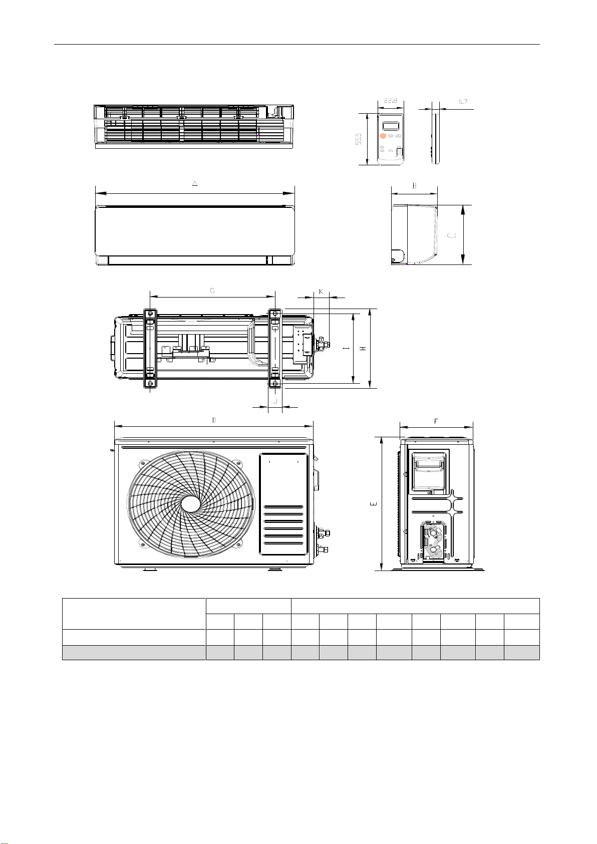
Air Conditioner Service Manual
8
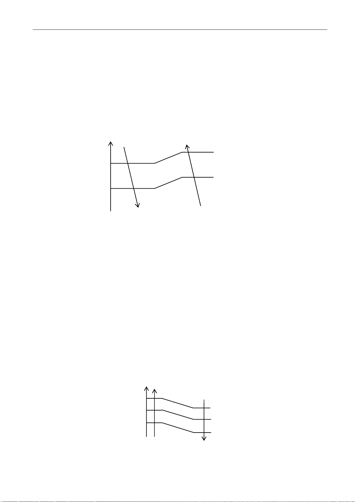
overheat protection. The compressor drops its frequency toward to F1 level until IPT≤52℃
If IPT≤52℃and keep for 5 minutes, control system doesn’t limit running frequency.
If IPT>62℃, control system shut down compressor, and recover while IPT drop less than 50℃.
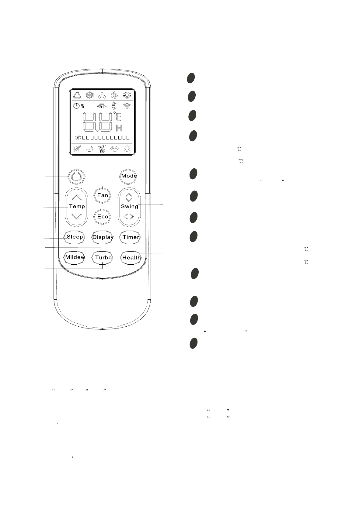
6. “SLEEP” mode
When the SLEEP button is pressed, the AC operates as following:
zThe indoor fan speed is set at low speed, the power lamp and the sleep lamp is on, the
display of temperature will close after 5 minutes.
zWhen selecting COOLING/DRY operation with SLEEP mode, the set temperature will be
raised by 1℃1 hour later and by 2℃2 hour later.
zWhen selecting HEATING operation with SLEEP mode, the set temperature will be dropped by
1℃1 hour later and 2℃2 hours later.
zAfter the System operates in SLEEP mode for 8 hours, it will stop automatically.
7. EMERGENCY Operation
When the EMERGENCY Operation switch is pressed one time, COOLING mode is selected
and if the EMERGENCY Operation switch press again within 3s, HEATING mode selected, while
press once again, the unit will switch off.
When the remote controller missing, failed or the batteries run down, press the EMERGENCY
Operation switch on front of the indoor unit for function test.
NOTE: Do not press the EMERGEMCY Operation switch during normal operation.
8. AUTO-RESTART Function (Option)
While air conditioner is operating in one mode, all of its operation data, such as working mode,
preset temperature etc. would be memorized into IC by main PCB. If power supply cut off due to
reasons and recover again, the AUTO-RESTART function will set
synchronously and the air
conditioner would work at the same mode as before.
Auto-restart Pre-setting (optional):
If Auto-restart function is needed, follow the steps below to activate this function:
1) Pulling the air-con's plug out of socket.
2) Pressing and holding the Emergency button (ON/OFF) on the indoor, then insert the plug
into the socket again.
3) Keep pressing the Emergency button for more than 10 seconds until three short beeps
heard, the Auto-restart function been activated.
9. Protection and Failure Display
zWhen protection display is available, controller will show error code, digital LED shows
error code and setting temperature by turns.
zIf there is more than one failure, it will show error codes according to the error list sequence.
zTo insure the signal communication of indoor and outdoor unit, any failure code relates to
outdoor unit will remain display for 2 minutes maximum after it’s recovered.
zAmong all the failure codes, sensor failure can be recovery automatically once it comes normal.


 null")