Banshee 700 User manual

© 2012 – Banshee Helicopters GmbH Page 1
!
1.!General)information)....................................................................................................)2!
1.!Equipment)recommendation).......................................................................................)3!
1.!Gear)assembly).............................................................................................................)4!
4.!Main)rotor)assembly)...................................................................................................)9!
5.!Tail)rotor)assembly)....................................................................................................)12!
6.!Chassis)assembly).......................................................................................................)16!
7.!Final)assembly)...........................................................................................................)21!
8.!RC)installation)...........................................................................................................)25!
9.!Video)tutorials)and)Links)...........................................................................................)31!
10.!Important)safety)information)..................................................................................)31!

© 2012 – Banshee Helicopters GmbH Page 2
1. General information
Technical features:
•3-speed belt drive
•Automatic tail rotor drive belt tensioner/-spring damper
•Main drive belt tensioner
•30 mm carbon-fibre, strutless, tail boom
•Straight swashplate linkage
•Extremely small, compact design with high torsional stiffness
•Centre of gravity close to the rotor plane
•Double (x 2 separate units) needle bearing clutch
Technical specifications:B
•Basic weight of the mechanics including canopy: 1,7 Kg´s
•All up weight with standard equipment (3xBLS452, 1xBLS251, Jive 120+ HV,
Pyro 700, BeastX, Maniac³710 mm, 115 mm tail blades, canopy): ~2950 g´s
•Main rotor speed: 1000-2300 U/min
•Variable reduction ratio between motor an main rotor:
o18Z !1 : 12
o19Z !1 : 11,37
o20Z !1 : 10,8
o21Z !1 : 10,28
o22Z !1 : 9,81
o23Z !1 : 9,39
o24Z !1 : 9
o25Z !1 : 8,64
•Ratio between main rotor and tail rotor: 1 : 5,54
•Battery cell size: Maximum 60 mm width and 60 mm height

© 2012 – Banshee Helicopters GmbH Page 3
1. Equipment recommendation
Motor
Only motors with 30 mm bolt circle possible!
Space for up to 65 mm outer diameter.
6S: Kontronik Pyro 650-65, Kontronik Pyro 700-52
10S: Kontronik Pyro 650-62, Kontronik Pyro 700-52
12S: Kontronik Pyro 700-52, Kontronik Pyro 800-48,
Scorpion HK 4525, 4530, 4535, 4540
14S: Kontronik Pyro 800-48
Controller
Kontronik Helijive 120 HV, YGE 160 HV, Kontronik Kosmik 200
Battery
6-14S 4000-5000 mAh (60 x 59 mm)
SP-Servos
Futaba BLS 452, Futaba BLS 156/175 HV, MKS HBL950 HV
Tail-Servos
Futaba BLS 251, Futaba BLS 256 HV, MKS HBL980 HV
Flybarless
Mini-V-Stabi, AC-3X, Microbeast
Tail rotor blades
Rotortech 95 -120 mm (light-weight)
1000-1900 RPM (3D): 105-120 mm
1900-2100 RPM (Extreme 3D): 105 mm
2100-2300 RPM (High-Speed): 95 mm
Main rotor blades
Flybarless between 690-720 mm with low-lead
© 2012 – Banshee Helicopters GmbH Page 4
1. Gear assembly
General instructions prior to gear assembly.
All screwings have to be secured with Loctite medium strength threadlock. Please
degrease new screws before use. It is recommended to repeatedly check all thread-
ed joints in order to prevent any screw from becoming loose. In practice, hex screw-
drivers and wrenches of Wera or Wiha have proven to be suitable.
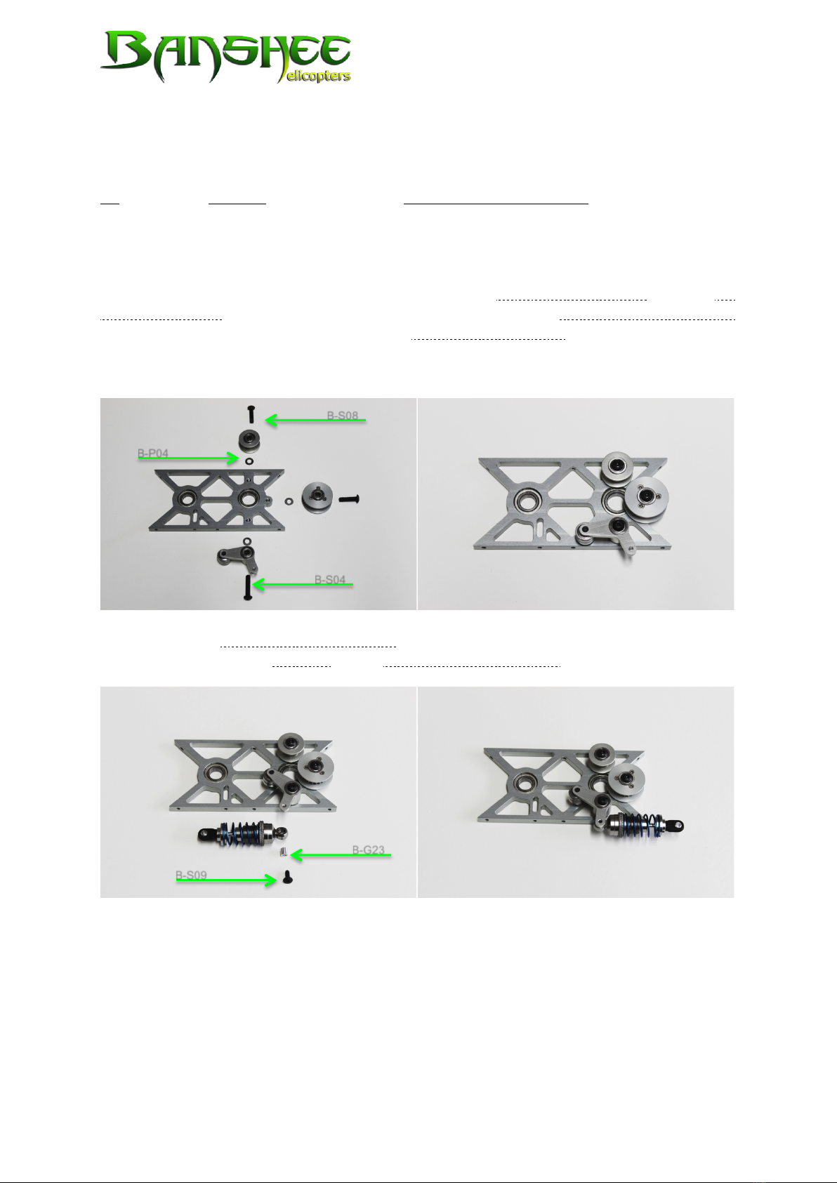
Start with the mechanical gear assembly. Screw the rear belt guide roller and the tail
belt guide pulley with a pan head bolt M4 x 16 (B-S08) and the rear belt tensioner lever
with a pan head bolt M4 x 20 (B-S04) to the bottom bearing plate. Place a thrust washer
4x8x0.2 (B-P04) between each of the bearings and the bearing plate. Please make sure
to position all components as shown in the pictures below.
Then screw the oil filled shock absorber with a pan head bolt with flange M3 x 8 (B-S09)
and the corresponding bushing to the rear belt tensioner lever.
B-S04
B-S08
B-P04
B-G23
B-S09

© 2012 – Banshee Helicopters GmbH Page 5
Next, the main rotor shaft is connected to the main pulley 72Z. We recommend to put
a small amount of grease over the part of the shaft where the pulley will be mounted.
Slide the shaft with the drilling that is further away from the shaft end into the main
pulley so that it protrudes slightly past the pulley.
Make sure to tighten fast the main rotor shaft to the pulley with a M5 x 21,5 special
bolt (B-S03) and a hex nut M5 (B-S18). The nut is kept in place in the pulley by positive
locking.
Now connect the intermediate shaft to the tail pulley 48Z. Make sure that the tail pul-
ley is flush with the shaft end and that the grub screw M4 x 4 (B-S12) is vertical to the
flat spot on the shaft. Using a small amount of lubricant may facilitate sliding the shaft
into the pulley.
B-S03
B-S18
B-S12
© 2012 – Banshee Helicopters GmbH Page 6
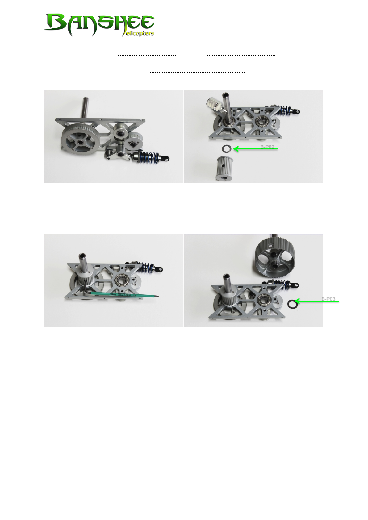
Insert the assembled intermediate shaft into the bottom bearing plate and fix it with
the intermediate shaft pulley 24Z as shown in the pictures below. Use a grub screw
M5 x 5 (B-S13) to tighten fast the intermediate shaft pulley 24Z. Place a thrust washer
10x16x0.2 (B-P02) between the intermediate shaft pulley 24Z and the bearing.
It is important to ensure that the grub screw is correctly tightened to the flat spot on
the shaft and that there is no axial play between the pulleys. In order to do so we
recommend you to slowly tighten the grub screw and slightly turn the pulley to test
the fit. For permanent hold tighten the grub screw carefully with a hex screwdriver.
Push the main rotor shaft downward into the bottom bearing plate. Place a thrust
washer 12x18x0.2 (B-P03) between pulley and bearing.
B-P02
B-P03

© 2012 – Banshee Helicopters GmbH Page 7
For the assembly of the main belt, first mount the belt around the pulley 24Z of the
intermediate shaft and then put the main rotor shaft with the main pulley 72Z through
the bottom bearing plate. Once the main belt is mounted around both pulleys slide
both thrust washers (B-P02) and (B-P03) on the shafts. Before sliding the middle bearing
plate on the shaft, position the main belt tensioner in the guide slot provided. You
need to place a thrust washer 4x8x0.5 (B-P01) on each side of the main belt tensioner.
Before you do so, put some lubricant on both shaft ends of the main belt tensioner as
shown in the picture.
B-P02
B-P03
B-P01
© 2012 – Banshee Helicopters GmbH Page 8
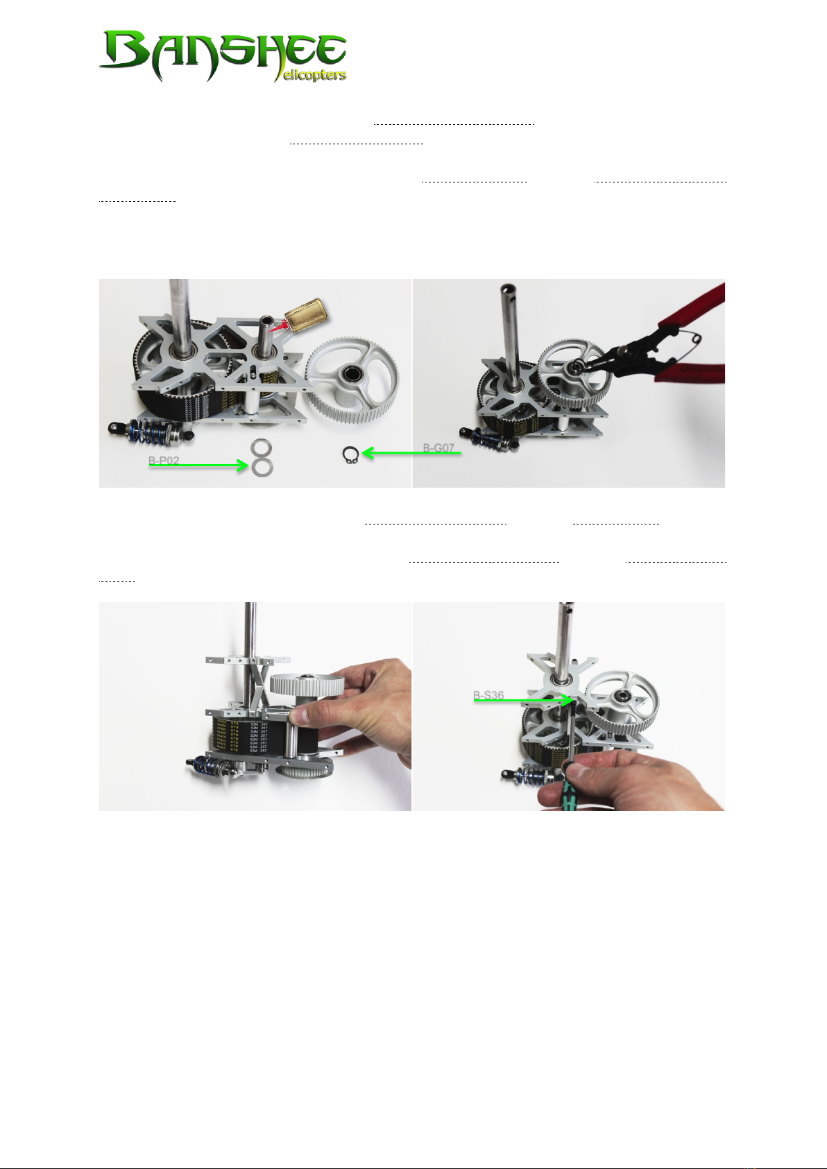
Continue with the assembly of the freewheel pulley 72Z. Slip two thrust washers
10x16x0.2 (B-P02) onto the intermediate shaft first. Before sliding on the freewheel pul-
ley lightly lubricate the intermediate shaft. Secure the freewheel pulley with a circlip
(B-G07) on the intermediate shaft. If both the tail pulley 48Z and the intermediate shaft
pulley 24Z are correctly assembled (no gap), you will find a minimum axial backlash
which is necessary for the smooth run of the freewheel. You need to expand the cir-
clip with special circlip pliers and then place it in the groove provided. You must not
expand the circlip too strongly since its secure fit will then no longer be guaranteed.
We proceed to the assembly of the dome bearing plate and the dome brace. In order
to avoid any twisting when assembling the chassis later on, temporarily screw the
dome brace without adding Loctite to the middle bearing plate and the dome bearing
plate. Use 4 cylinder head bolts hex M3 x 8 (B-S36).
The assembly of the gearing unit is completed.
B-P02
B-G07
B-S36
© 2012 – Banshee Helicopters GmbH Page 9
4. Main rotor assembly
The main rotor is one of the most critical safety components of model helicopters.
Please proceed with caution.
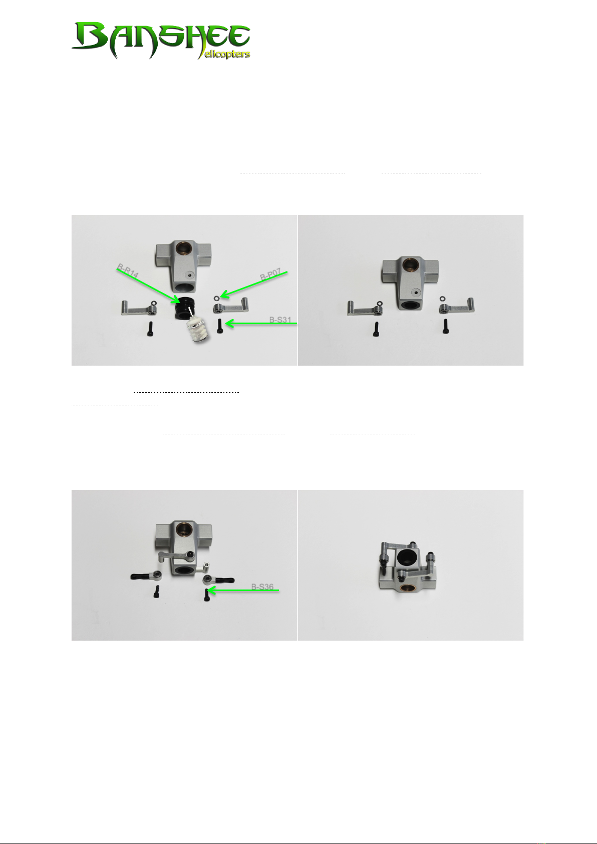
Start with the positioning of the rotor head damping in the main rotor housing. First of
all, take the rotor head damping and add a small amount of lubricant in the area of
the rubber rings (B-R14). Then press it into the main rotor housing until it is flush.
Secure the rotor head damping with the cylinder head bolts hex M3 x 12 (B-S31) of the
SP-towing arms that are both tightened with one additional thrust washer 3x6x0.2
(B-P07) each.
Then screw the carrier ball joint heads to the SP-towing arms. Use cylinder head
bolts hex M3 x 8 (B-S36). Make sure that the SP-towing arms point in the right direction
as shown in the pictures below and that the preferred direction for clipping on the ball
joints is correct (lettering facing to the outside).
B-R14
B-S31
B-P07
B-S36
© 2012 – Banshee Helicopters GmbH Page 10
Continue with the assembly of the rotor head. Degrease the hollow feathering shafts,
apply a small amount of Loctite and push them into the main rotor housing as far as
they will go (!). If it is difficult to push them in you can use a vise carefully. Please
ensure that the side with the smaller shaft diameter is facing outward. Remove any
excess Loctite.
Repair information: You can disassemble a bent feathering shaft after a crash with
a small hand vise or a pipe wrench. The needle bearings are usually crash-resistant.
!
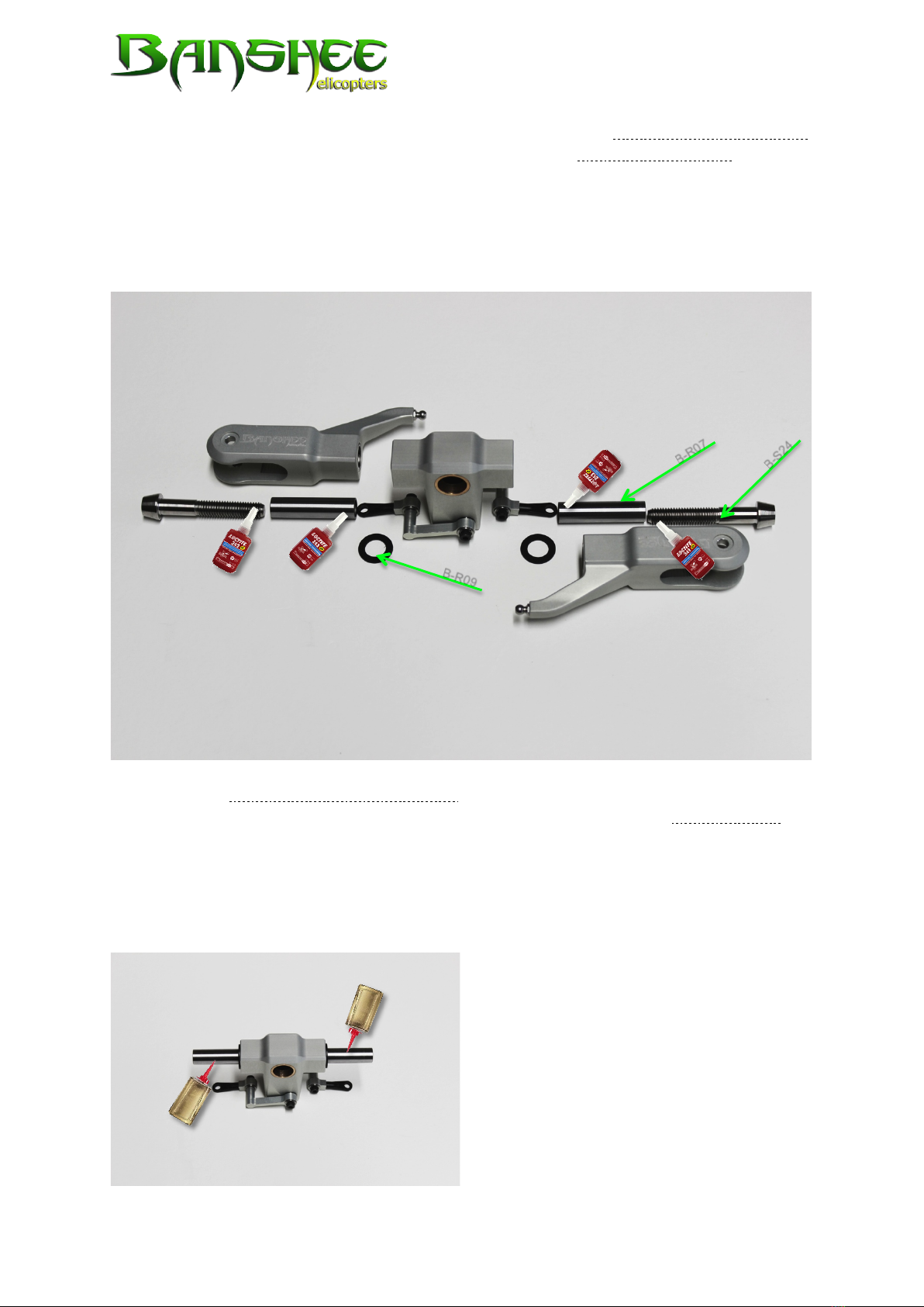
Now slide the special blade holder spacer made of Delrin (B-R09) on the shaft. Apply a
small amount of lubricant on the feathering shafts before sliding the blade holder with
the pre-assembled needle bearings on the feathering shafts. It might be a little bit
difficult to move it on the shaft. This is normal and will cease after the first few flights
once the shaft has been polished in the area of the needle bearings. Subsequently,
the blade holder will run smoother, too. This does not have an impact on the flight
characteristics and may therefore be disregarded.
B-S24
B-R09
B-R07
Table of contents


