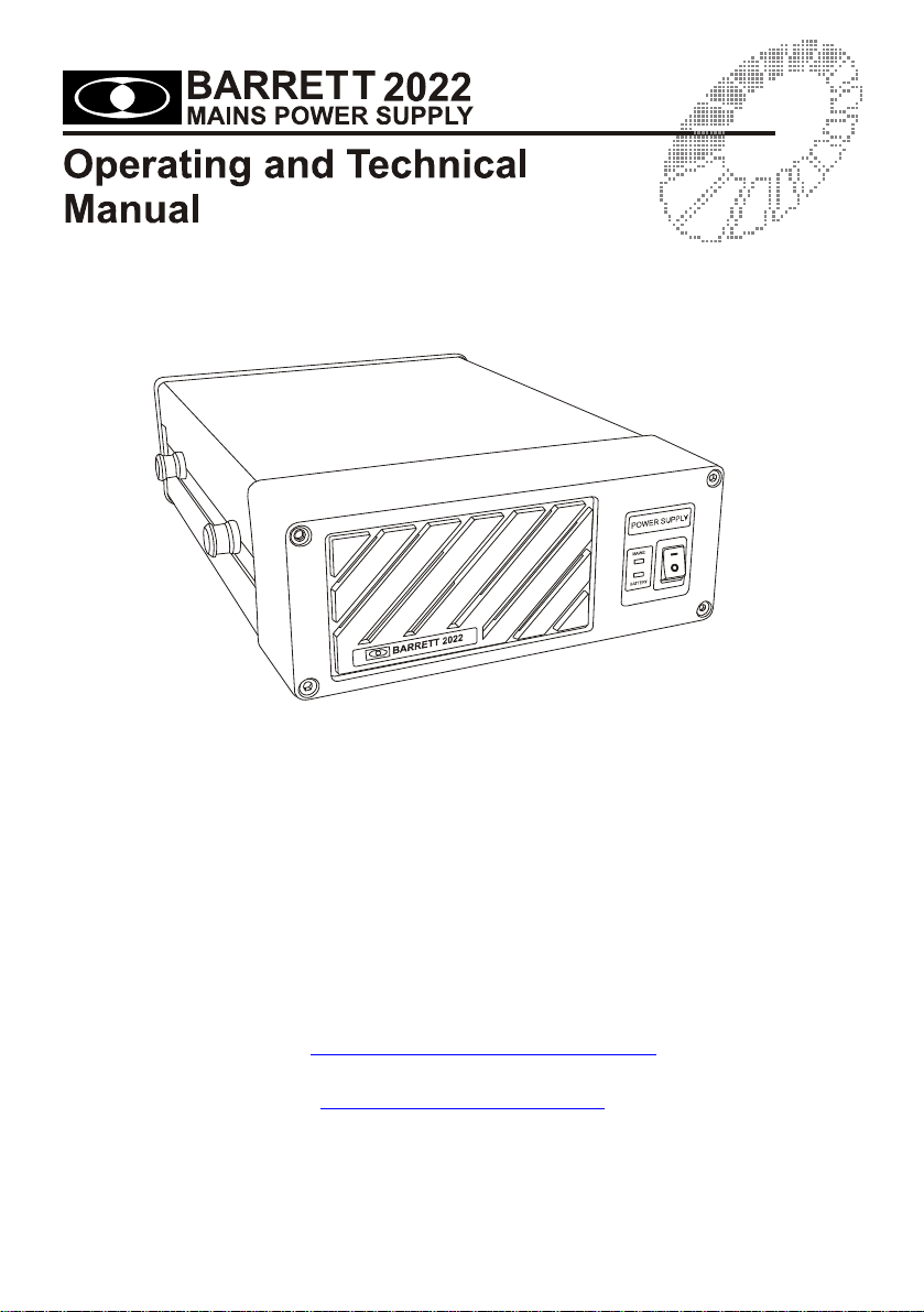
Barrett 2022 User manual
BCM20220/10
© Barrett Communications
Head Office:
Barrett Communications Pty Ltd
47 Discovery Drive, Bibra Lake, WA 6163 Australia
Tel: +61 8 9434 1700 Fax: +61 8 9418 6757
Email: [email protected]
www.barrettcommunications.com.au

2
Introduction
The Barrett 2022 Power Supply is designed to provide regulated power to one 2050
transceiver and one accessory such as a 2023 modem. The 2022 also has provision for a
battery backup system in case of mains power failure. The battery backup incorporates a true
automatic no break change over circuit with battery charging system.
Specifications
Output Voltage 13.8 VDC
Output Current 21 Amps Max
Input Voltage 88-256 VAC @ 50/60Hz auto ranging.
Input Connector IEC Type
Overload Protection 22 Amps - Auto-recovery
Over Voltage Protection Auto - Recovery
Battery Charge Voltage 13.1 VDC
Battery Charge Current 3 Amps Max
Operation
The Barrett 2022 is a low noise switch mode power supply that is capable of delivering 13.8V
at 21 Amps continuously with a mains input supply that can vary from 88 VAC to 256 VAC.
This combined with the ability of the power supply to operate with a backup battery, makes the
2022 ideal for use in areas where mains voltages vary dramatically and occasionally fail
altogether. An internal fan provides airflow to keep the power supply operating at a safe
temperature level even during the most demanding duty cycles.
The 2022 is normally operated from a mains supply. When the mains supply is connected and
the power switch is in the ON position, the upper Green indicator LED, next to the power
switch, will be illuminated. When the 2022 power supply is operated with the optional backup
battery connected, again if the mains supply is available, the upper Green indicator LED will be
illuminated. If the mains supply fails the 2022 will automatically switch over to the backup
battery. In this case the lower Indicator LED will show a Green indication. The lower indicator
LED will change to indicate RED and the battery will be disconnected when the battery voltage
falls below a safe level.
If this occurs you must either wait for the mains supply to be re-established or a fresh battery
should be connected to the power supply. When the mains supply is re-established the 2022
power supply will again take the load and the battery will commence charging.
The 2022 Power Supply also contains an 8ohm 2 Watt loudspeaker for use when the 2050 is
configured as a base station. The volume for this speaker is controlled from the front panel of
the 2050 Transceiver.
The 2022 is supplied in a standard bench mounting configuration. Several other mounting
options are available including a 19” Rack mounting kit that can mount one or two units or a
set of stacking plates can also be supplied to secure two, three or four units together.

3
Technical Manual
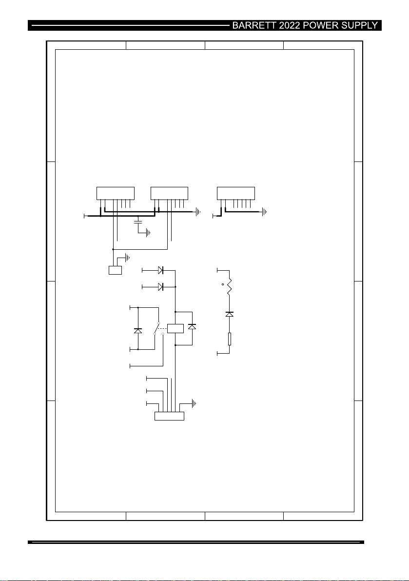
Circuit Description
The rear panel PCB of the 2022 provides an interface between the switch mode module,
external backup battery and device outputs. The front PCB contains the control circuitry for the
automatic battery switch over system. The battery switch over control is based around the
quad voltage comparator U1.
U1B forms the control section for the switch mode module. With the switch mode module
turned on and operating correctly, a voltage of 5.4V is present at Pin 6 of U1 and the voltage at
Pin 7 is 4.8V. This results in the output of the comparator being low. The low output keeps Q1
in the OFF state and relay RL1 is switched to the switch mode module. If the voltage from the
switch mode falls below 12.5V, from loss of mains voltage or a fault in the switch mode
module, then the output of U1B will go HIGH causing Q1 to turn on. Once Q1 turns on the
relay is switched over to the battery supply. The power supply will stay in this condition until
the mains voltage is restored or the switch mode fault is cleared.
To prolong the life of the backup battery it is important that it is not discharged excessively. To
ensure that this never occurs, the voltage of the battery is monitored by U1C. When a battery
is connected to the power supply there are three possible states. Switch mode module
operating correctly, battery being trickle charged. Switch mode module off, battery voltage high
and supplying power to the load. Switch mode off, battery voltage low and no power being
supplied to the load.
In the first situation with the switch mode ON and the battery being charged, U1C has no
control over the relay RL1. In this operating state the switch mode module is keeping the
output of U1B LOW and the Relay RL1 switched to provide the output voltage from the switch
mode module.
Once the switch mode module fails, either due to a fault condition or the loss of mains voltage,
then this part of the circuit becomes active. When a fully charged battery is connected a
voltage of 5.3V is present at Pin 9 of U1. The voltage regulator IC U2 keeps a constant voltage
of 5V on Pin 8 of U1. As the positive input of comparator U1C is at a higher voltage than the
negative input, the output of U1C is High. This results in a positive voltage on the gate of
MOSFET Q1, turning it ON. Once this MOSFET turns on relay RL1 is switched and the output
voltage is supplied by the batteries.
The voltage of the battery is constantly monitored by this circuit during normal operation. The
voltage of a battery drops as the battery is being discharged and the corresponding voltage at
Pin 9 of U1 will also fall. Once this voltage falls below 5V, the output of U1C will change from a
High to a Low state. This will result in the MOSFET Q1 turning off and relay RL1 switching the
battery away from the output devices. To avoid the battery circuit from oscillating, a large
hysteresis loop is designed into the circuit.
If the mains voltage continues to remain unavailable and the battery falls below a safe value
the only way to restore power is to disconnect the discharged battery and replace it with a fully
charged one.

Battery charge circuit
The battery is trickle charged through resistor R9, diode D3 and thermistor RT1. D3 is used to
stop the battery from discharging back into the power supply if the mains voltage is lost.
Battery charge current is controlled by R9 and RT1. If the battery charge is low then it will
demand a higher charging current from the power supply. This will cause RT1 to heat up
resulting in an increase in the resistance of the thermistor and a reduction in the current
supplied to the battery. This circuit limits the maximum charge current to the battery to 3 Amps.
Using the 2022 power supply with a backup battery
4

1 2 34
A
B
C
D
4
321
D
C
B
A
R1
1K R3
390K
R5
5K6
R7
10K
VPSU VPSU
C1
0U1
R2
1K
R6
24K
R8
39K
VBatt
VBatt
312
2
5
4U1A
LM339-2
1
7
6U1B
LM339-2
14
9
8
U1C
LM339-2
13 11
10
U1D
LM339-2
Battery switches out at 11V
and stays latched until Mains returns or battery is replaced
PSU switches out at 10.5v
PSU switches in at 11v
R13
15K
Vin
R10
15K
R11
1K
VPSU
+13V8 VBatt
R12
1K
VBatt
R14
1K
VBatt
R16
100K
R17
100K
PSU+
PSU-
BATT-BBATT-G
D7
LED Green
GREEN RED
D9
HLMP-0800
D8
BAV70
Vin
U2
LM4040DIM3-50
U3
LM4040DIM3-50
R18
3K9
R19 82K
Q1
BSP17
C2
10U
C3
47U
Q3
2N7002
R4
10K
VPSU Q2
NDT456
D1
BAV70
C4
0U1
1
2
3
4
5
6
P1
CON6
Rear Panel
VBattVPSU+13V8
Speaker
Control
VBatt VPSUVin
D2
BAV70
1
2
SPK1
CON2
1
2
SPK2
CON2
C5
0U1
R9
1K
Barrett 2022 Power Supply Front Panel Schematic
Drawing No: 2022D02-A2
5

6
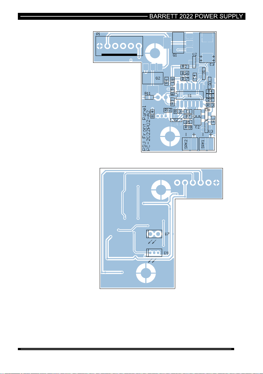
Barrett 2022 Power Supply Front Panel PCB
Drawing No: 2022P02-A2
7

8
Parts list 2022 power supply front panel PCB
Component
Designator Description Barrett Part
Number
C1 Cap 100nF 20% 63V 1206 NO PHILIPS CP-00916
C2 Cap 10uF 20% Tant 25V Case C CP-01575
C3 Cap 47uF 16v 10% Case D CP-11665
C4 Cap 100nF 20% 63V 1206 NO PHILIPS CP-00916
C5 Cap 100nF 20% 63V 1206 NO PHILIPS CP-00916
D1 Di BAV70 SMD DI-03316
D7 Led Green 5x2 rectangle LE-02909
D8 Di BAV70 SMD DI-03316
D9 Led Rectangular Bi-color LE-02918
P1 Plug 6 pin Polarised CN-14106
Q1 Trans BSP17 SOT223 Mosfet TR-02207
Q2 Trans NDT456 SOT-223 PCH Power FET TR-02292
Q3 Trans 2N7002 LT-1 Fet SOT23 TR-02282
R1 Res 1k 5% 0.063W 0603 NB RE-10287
R2 Res 1k 5% 0.063W 0603 NB RE-10287
R3 Res 390k 0.063W 5% 0603 NB RE-10319
R4 Res 10k 5% 0.063W 0603 NB RE-10277
R5 Res 5k6 0.063W 5% 0603 NB RE-10328
R6 Res 22k 0.063W 5% 0603 NB RE-10311
R7 Res 10k 5% 0.063W 0603 NB RE-10277
R8 Res 39k 0.063W 5% 0603 NB RE-10322
R9 Res 1k 5% 0.063W 0603 NB RE-10287
R10 Res 15k 0.063W 5% 0603 NB RE-10307
R11 Res 1k 5% 0.063W 0603 NB RE-10287
R12 Res 1k 5% 0.063W 0603 NB RE-10287
R13 Res 15k 0.063W 5% 0603 NB RE-10307
R14 Res 1k 5% 0.063W 0603 NB RE-10287
R16 Res 100k 5% 0.063W 0603 NB RE-10291
R17 Res 100k 5% 0.063W 0603 NB RE-10291
R18 Res 3K9 0.063W 5% 0603 NB RE-10324
R19 Res 82k 0.063W 5% 0603 NB RE-10344
U1 IC LM339D SO14 SMD IC-02730
U2 Di LM4040DIM3-50 SOT23 DI-03355
U3 Di LM4040DIM3-50 SOT23 DI-03355
C1 Cap 100nF 20% 63V 1206 NO PHILIPS CP-00916
C2 Cap 10uF 20% Tant 25V Case C CP-01575
C3 Cap 47uF 16v 10% Case D CP-11665
C4 Cap 100nF 20% 63V 1206 NO PHILIPS CP-00916
C5 Cap 100nF 20% 63V 1206 NO PHILIPS CP-00916
D1 Di BAV70 SMD DI-03316
1 2 34
A
B
C
D
4
321
D
C
B
A
A1
A2
1
2
3
4
5
P1
7W2 Male
A1
A2
1
2
3
4
5
P2
7W2 Female
A1
A2
1
2
3
4
5
P3
7W2 Female
Speaker
Speaker
Battery
13V8 out
13V8 out
Fan
Fan
VBattVPSU
RL1
REL EP1-3L1S-SPDT
R9
0.1R/5W
D3
1N5821
RT1
THERMISTOR
1
2
P5
CON2
Fan
D4
1N5404
+13V8VBatt VPSU
VPSUVBatt
+13V8
VBatt
Battery Charging circuit
1
2
3
4
5
6
P4
CON6
Control Board
C5
0U1
VBatt VPSU +13V8
Speaker
Control
D1
1N4148
D2
1N4148
D5
1N4148
Barrett 2022 Power Supply Rear Panel Schematic
Drawing No: 2022D1-A5
9
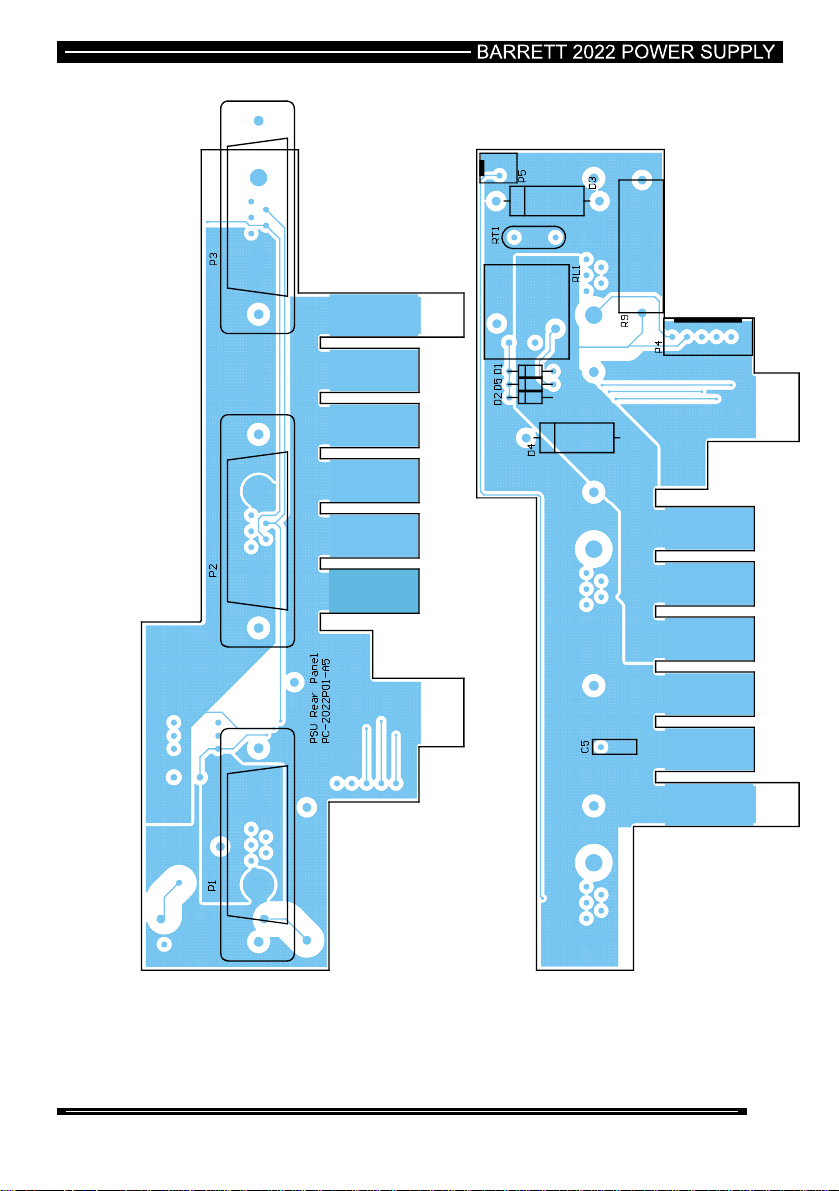
2022 Power Supply Rear Panel PCB
Drawing No: 2022P01-A5
10

11
Parts list 2022 power supply rear panel PCB
Component
Designator Description Barrett Part Number
C5 Cap 100nF Mono 5mm SPC CP-01018
D1 Di 1N914/1N4148 DI-03302
D2 Di 1N914/1N4148 DI-03302
D3 Di 1N5821 Power DI-03353
D4 Di 1N5404 Power DI-03313
D5 Di 1N914/1N4148 DI-03302
P1 Conn D 7W2 (2P/5D) M ST CN-24150
P2 Conn D 7W2 (2P/5D) F ST CN-24149
P3 Conn D 7W2 (2P/5D) F ST CN-24149
P4 Plug 6 pin Polarised CN-14106
P5 Plug 2 pin Polarised CN-14101
R9 Res 0R1 5W WW RE-00751
RL1 Relay EP1-3LIS NEC RL-05020
RT1 Fuse Resettable Polyswitch 4A FU-02534

12
Limited 3 Year Warranty
Barrett Communications Pty Ltd provides a maximum three year warranty on all
equipment it manufactures which is to be used expressly for high frequency, single
sideband radio communications. This warranty covers faults arising from defects in
design, workmanship or materials. Please note that this warranty does not cover
batteries.
Should any fault due to bad design, workmanship or materials be proven at any time
within the warranty period, the company will rectify such fault free of charge providing
the equipment is returned freight paid to Barrett Communications Pty Ltd or to an
authorised service centre. The warranty period for all products is twelve months after
shipment from the factory or an authorised Barrett agent or dealer. In the event that the
end user completes and lodges warranty registration documents within three months of
receipt of the shipment from the factory or an authorised Barrett agent or dealer, the
warranty period shall be extended by an extra twenty four months giving a total warranty
period of three years.
This warranty shall not cover any abuse, accident, improper installation, connection,
adjustment or use other than in accordance with the instructions issued by the
company.
In addition, this warranty shall not cover the distance which transceiver products will
operate over or quality of transmission or reception as a result of unfavourable
environmental conditions. Nor shall this warranty cover the quality of transmission and
reception of transceivers mounted in vehicles or vessels that have not been sufficiently
electrically suppressed.
Subject to the matters set out in this warranty, no liability, expressed or implied is
accepted for any consequential loss, damage or injury arising as a result of a fault in the
equipment and, all expressed or implied warranties as to quality or fitness for any
purpose are hereby excluded.
This warranty does not extend to products supplied by the company which are not
designed or manufactured by it. Barrett Communications Pty Ltd will however make
every endeavour to ensure that the purchaser receives full benefit on any warranty
given by the manufacturer.
This warranty is restricted to the original purchaser. Where the original purchaser is a
reseller who has purchased for the purpose of resale, warranty shall be extended to the
reseller’s customer.

13
Warranty registration and customer support
Thank you for purchasing Barrett HF communications products.
The standard and automatic warranty on Barrett products is one year. By completing
the registration form on the next page and sending it to us by mail, fax or email, this
warranty will be extended to a total of three years at no extra cost.
By registering for the extended warranty period Barrett Communications will also
provide the following services:-
Your contact details will be registered against the serial numbers of the
equipment.
Barrett Communications will keep you informed of any developments relating to
this equipment.
Barrett Communications will provide you with direct access to a support
telephone contact line manned from 0000hrs GMT to 1600 Hrs GMT, 7 days a
week.
The registration forms can be returned by mail, (no postage stamp required in Australia)
or by facsimile (08) 9418 6757 (International + (618) 9418 6757).
If you have access to the Internet you can use the warranty registration page in the
support section of our website to register your warranty form. Please go to
www.barrettcommunications.com.au
We will mail or email you if you have registered via the Internet details of your support
package within 7 days of receiving your completed registration form.
Barrett Communications is proud of its reputation for support of its customers. This
registration process has been introduced so that we may continue to improve our level
of support to you.
Table of contents


