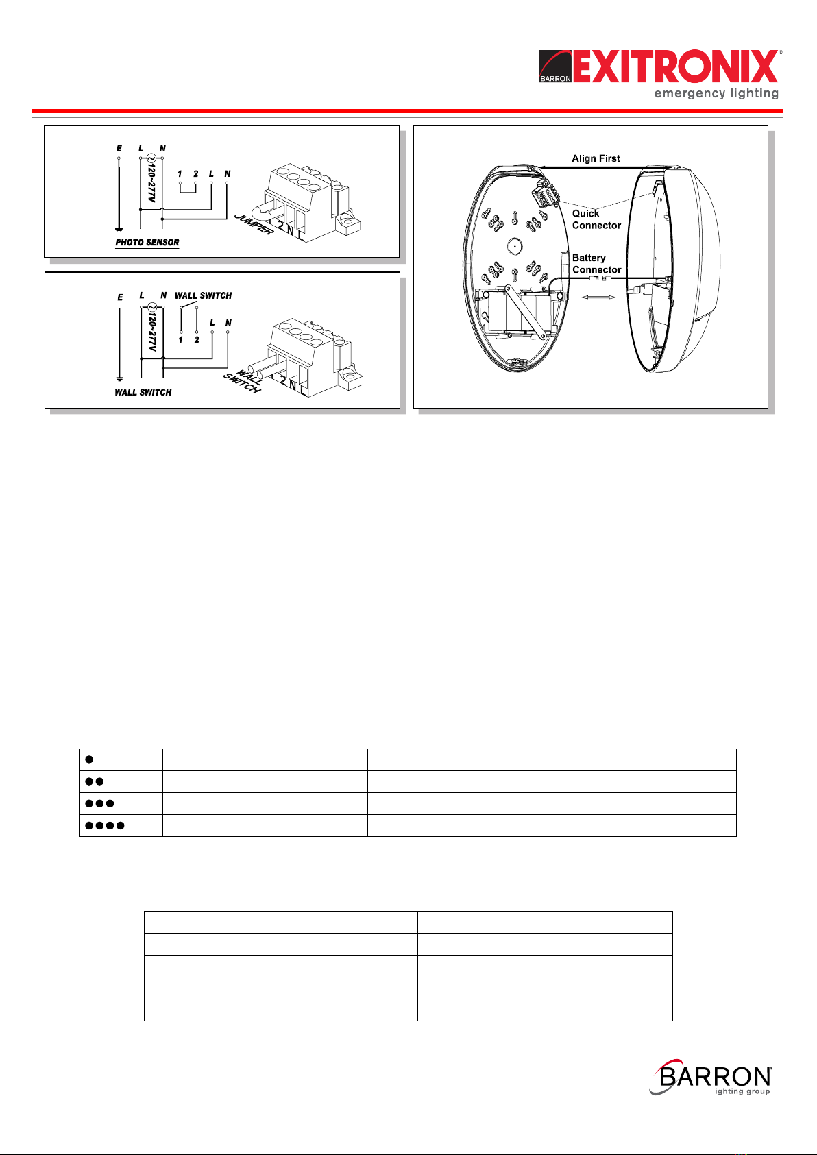
BARRON EXITRONIX TRL Series User manual

IMPORTANT SAFEGUARDS
READ AND FOLLOW ALL SAFETY INSTRUCTIONS.
When using electrical equipment, basic safety precautions should always be followed including the following:
• DISCONNECT AC POWER SUPPLY BEFORE SERVICING.
• Installation and servicing of this equipment should be performed by qualified service personnel only.
• Ensure that the electrical wiring conforms to the National Electrical Code NEC® and local regulations
if applicable.
• Do not mount near gas or electrical heaters.
• Do not use outdoors.
• Equipment should be mounted in locations and at heights where it will not be readily subjected to tampering
by unauthorized personnel.
• The use of accessory equipment not recommended by the manufacturer may cause an unsafe condition.
• Any modification or use of non-original components will void the warranty and product liability.
• Do not use this equipment for other than intended use.
• Allow battery to charge for 24 hours before first use.
• For use with metal enclosed wiring systems.
SAVE THESE INSTRUCTIONS!
Technical Support ■ (623) 580-8943 ■ [email protected]
TRL Series
Installation Instructions
XXXXXXXX REV 1 - 07/23 1
800-533-3948 www.barronltg.com

Fig. 1
Fig. 3
Fig. 2
TRL Series
Installation Instructions
XXXXXXXX REV 1 - 07/23 2
800-533-3948 www.barronltg.com
LED Module Replacement
LED module with 11W high performance power LED. If need, please contact factory.
Function:
1. For normal lighting use, the fixture can be configured for automatic operation by the built-in daylight photo sensor or
can be switched through an external switch. For battery backup models the fixture will illuminate from the battery
power on loss of normal AC, regardless of the photo sensor or wall switch operation.
2. For photo sensor operation, leave the jumper between terminals 1 and 2 and slide the slide switch to the Photo
Sensor position (see Fig. 4 for wiring connections). The photo sensor will turn the fixture on when the ambient
lighting < 10 Lux, and off when the ambient lighting > 30 Lux.
3. For an external switch: remove the jumper between terminals 1 and 2, connect the switch device between terminals
1 and 2, and slide the slide switch to the Wall Switch position (see Fig. 5 for wiring connections). The external switch
connections must be fully isolated from any other circuitry.
4. For “Normally Off” standby battery backup operation only: connect the AC power as shown in Fig. 2 or 3 below and
remove the jumper between terminals 1 and 2. The slide switch is defeated in this mode so it can be in either the
Photo Sensor or Wall Switch positions.
Installation
1. Open the front cover. (Fig. 1)
2. Installation using J-box. (Fig. 2)
3. Installation using conduit. (Fig. 3)
4. Wire diagram for photo sensor function (Fig. 4)
5. Wire diagram for wall switch function (Fig. 5)
6. Assembly and quick connector (Fig. 6)

Fig. 4
Fig. 5
Fig. 6
TRL Series
Installation Instructions
XXXXXXXX REV 1 - 07/23 3
800-533-3948 www.barronltg.com
Operation
The battery in this unit may not be fully charged. After electricity is connected to the unit for at least 24 hours, then normal
operation of this unit should take effect. To check, press the “TEST” button. The EXIT sign should stay illuminated by
battery backup and the LED indicator will be turned off. Release the “TEST” button, LED indicator will be turned on.
In accordance with NFPA 101, your emergency lighting system must be tested monthly for a minimum of 30 seconds and
annually for 90 minutes. Refer to your local codes for any additional requirements that may apply.
Testing and Reporting Instructions (-G2 and -G3 models)
1. When AC power is supplied to fixture, the unity will automatically initiate a self-test and self-diagnostic test as follows:
• Verifies battery disconnection, charger board failure at every 5 seconds.
• 1 minute self-testing every month.
• 30 minutes self-testing on every 6 months after installation.
• 90 minutes self-testing on every 12 months after installation.
2. Dual color LED lamp indicator shows the following status:
• Green color: On / Ready
Blinking: Testing
• Red color: (Service Alert)
• Service Alert LED Code (Red color LED lamp indicator)
Note: After solving the fault of emergency equipment, please press test button for 2 seconds then release to
reset. LED indicator will show green.
2. “-G2” and “-G3” models also have a manual test function, press test button as follows:
Press test button once (within 2 seconds)
Press test button twice (within 2 seconds)
30 seconds discharge test
Press test button 3 times (within 2 seconds)
Press test button 4 times (within 2 seconds)
*Press and hold test button for 8 seconds
3 minutes discharge test
30 minutes discharge test
90 minutes discharge test
Fixture will leave network and reset itself
*Note: only applies to “-G3” models. If you have problem to initiate provisioning or if you know
the unit belongs to other Guardian Network
One blink ON/pause (4 seconds)
Two blinks ON/pause (4 seconds)
Battery is not connect
Three blinks ON/pause (4 seconds)
Four blinks ON/pause (4 seconds)
Battery is shorted or battery voltage drops below an acceptable value
Charger board circuit fault
Transfer function failure

TRL Series
Installation Instructions
XXXXXXXX REV 1 - 07/23 4
800-533-3948 www.barronltg.com
Networking Operations for “-G3” Models
Model with "-G3" suffix is our world winning design equipped with "wireless testing and reporting" features. Unit that
has "-G3" suffix in its model number is capable of joining Guardian emergency lighting management system. It will be
part of a large testing system to be tested and report result wirelessly.
Once powered up and commissioning allowed, unit will automatically join Guardian network and get provisioned. Upon
the completion of the commissioning,unit will perform testing and report based on set schedules.
For more information about commissioning, configurations and testing, please visit website, https://www.barronltg.com
for details.
Table of contents
Other BARRON Outdoor Light manuals