Bauer Compressors P0 Manual

Instruction Manual and Replacement Parts List
BAUER Compressors, Inc. Phone: (757) 855-6006
1328 Azalea Garden Road Fax: (757) 855-6224
Norfolk, Virginia 23502-1944 www.bauercomp.com
April 17, 2013 3rd Edition, Rev 0 Chg 6 MNL-0096
© Bauer Compressors, Inc.
Breathing Air Purification Systems
and
Industrial Air Purification Systems
Breathing Air Purification Models
P0 P1 P2 P4
P5 P10 P31 P41
P42 P43
with Securus®Electronic Moisture Monitor System
P2S P5S P10S P14S
P42S P43S P12 P14
Industrial Air Purification Models
IP41 IP42 IP43
with Securus®Moisture Monitoring System
IP2S IP5S IP10S
IP41S IP42S IP43S
Purification Systems
Page i 3rd Edition, Rev 0 Chg 6
This information is believed to be accurate by Bauer Compressors, Inc., as of it’s date of publication,
but Bauer offers NO WARRANTY regarding the accuracy, or continuing accuracy, of the information
set forth herein. Bauer shall not be liable for inaccuracies in, or consequences resulting from, your use
of this information. All information supplied is in connection with sales of Bauer’s products, and is thus
subject to Bauer’s standard terms and conditions of sale. Bauer reserves the right to change this infor-
mation and has no obligation to update these materials. This information is copyrighted by Bauer Com-
pressors, Inc., and Bauer reserves to itself all rights to this publication. Bauer’s customers have no right
to reproduce, rewrite, modify, license or permit anyone else’s use of this information, without the
express written permission of Bauer Compressors, Inc.
EDITIONS, REVISIONS AND CHANGES
• An Edition is the original or a complete rewriting of the entire Manual.
• A Revision occurs whenever a complete Section or Appendix is rewritten or added.
• A Change occurs when individual pages, drawings or tables are changed.
^WARNING
This Instruction Manual and Replacement Parts List contains safety information and instructions for the
Air Purification Systems.
You must read, understand and follow all safety precautions and instructions.
3rd Edition May 11, 2005
Rev Chg Date Notes Auth
0 0 May 11, 2005 JD
0 1 Dec. 12, 2005 Changed Manual Condensate Drain Valve to P/N 073793 JD
0 2 Aug. 1, 2006 Corrected Figures 5-1, 5-4, 5-9 & 5-12.
Added Figures 5-8 and 5-16. JD
0 3 Jan. 17, 2007 Add P/N N24788 to P31 Purification System Parts list JD
0 4 Mar. 19, 2007 Life Span of Oil/Water Separator Lengthened JD
0 5 July 9, 2010 Updated High Flow Cartridge Removal SS
0 6 Apr. 17, 2013 Updated P31 Part numbers to B61.1 SS

MNL-0096
April 17, 2013 Page ii
Table of Contents
CHAPTER 1:- - - - - - - - - - - - - - - - - - - - - INTRODUCTION
1.1 HOW TO USE THIS MANUAL.........................................................................................................................................1
1.1.1 Manual Safety Notices.......................................................................................................................................................1
1.2 HOW TO USE THE REPLACEMENT PARTS LIST....................................................................................................2
1.3 HOW TO USE THE APPENDIX.......................................................................................................................................3
CHAPTER 2:- - - - - - - - - - - - - - - - PURIFICATION SYSTEM
2.1 INTRODUCTION................................................................................................................................................................4
2.1.1 General Purification System Procedures............................................................................................................................4
2.1.2 Chamber Safety Bore.........................................................................................................................................................4
2.1.3 Manual Condensate Drainage ............................................................................................................................................5
2.1.4 Model, Serial Number and Part Number Identification.....................................................................................................5
2.1.4.1 Compressor Dataplate.....................................................................................................................................................5
2.1.4.2 Purification System Dataplate ........................................................................................................................................6
2.1.4.3 Cartridge Installation Dataplate......................................................................................................................................6
2.1.5 Breathing Air Purification System Configurations............................................................................................................6
2.1.6 Industrial Purification System Configurations...................................................................................................................7
2.1.7 Cartridge Operating Life....................................................................................................................................................7
2.1.7.1 Calculating the Maximum Cartridge Operating Hours ..................................................................................................8
2.1.7.2 Calculating the Adjusted Cartridge Operating Hours.....................................................................................................8
2.1.7.3 Air Purification Cartridge Operating Hours Form........................................................................................................10
CHAPTER 3:- - - - SINGLE CHAMBER PURIFICATION SYSTEMS
3.1 APPLICABILITY..............................................................................................................................................................11
3.2 P0 PURIFICATION SYSTEM DESCRIPTION............................................................................................................11
3.2.1 Maintenance.....................................................................................................................................................................12
3.2.1.1 Replacing the Cartridge................................................................................................................................................12
3.2.1.2 Chamber Replacement Interval ...................................................................................................................................13
3.2.2 Replacement Parts List.....................................................................................................................................................15
3.3 P31 PURIFICATION SYSTEM.......................................................................................................................................17
3.3.1 Major Components...........................................................................................................................................................17
3.3.2 Configuration Options......................................................................................................................................................18
3.3.3 Maintenance.....................................................................................................................................................................19
3.3.3.1 Replacing the Cartridge................................................................................................................................................19
3.3.4 Replacement Parts List.....................................................................................................................................................20
CHAPTER 4:- - - - -MULTI-CHAMBER PURIFICATION SYSTEMS
4.1 APPLICABILITY..............................................................................................................................................................23
4.2 COMPONENTS LAYOUT...............................................................................................................................................23
4.3 COMPONENT DESCRIPTION ......................................................................................................................................24
4.3.1 Oil and Water Separator...................................................................................................................................................24
4.3.2 Chamber...........................................................................................................................................................................25
4.3.3 Cartridge...........................................................................................................................................................................25
4.3.3.1 Cartridge Handling .......................................................................................................................................................25
4.3.4 Condensate Drain Valve...................................................................................................................................................25

Purification Systems
Page iii 3rd Edition, Rev 0 Chg 6
4.3.5 Check Valves....................................................................................................................................................................26
4.3.6 Bleed Valve......................................................................................................................................................................26
4.3.7 Pressure Maintaining Valve .............................................................................................................................................26
4.3.8 Safety Valve .....................................................................................................................................................................26
4.4 MAINTENANCE...............................................................................................................................................................26
4.4.1 Oil and Water Separator...................................................................................................................................................26
4.4.2 Cartridge Replacement.....................................................................................................................................................27
4.4.2.1 Leaking at the Safety Bore............................................................................................................................................28
4.5 PURIFICATION CARTRIDGE APPLICABILITY......................................................................................................29
4.5.1 Purification Chamber Position References.......................................................................................................................29
4.6 PURIFICATION SYSTEM REPLACEMENT PARTS LIST......................................................................................31
4.6.1 P1 Purification System.....................................................................................................................................................31
4.6.2 P2 Purification System ....................................................................................................................................................32
4.6.3 P2S and IP2S Purification System ...................................................................................................................................33
4.6.4 P4 Purification System.....................................................................................................................................................34
4.6.5 P5 Purification System.....................................................................................................................................................35
4.6.6 P5S and IP5S Purification System ...................................................................................................................................36
4.6.7 P10 Purification System...................................................................................................................................................37
4.6.8 P10S and IP10S Purification System ...............................................................................................................................38
4.6.9 P10S II Purification System .............................................................................................................................................39
4.6.10 P41 and IP41 Purification System....................................................................................................................................40
4.6.11 P41S and IP41S Purification System ...............................................................................................................................41
4.6.12 P42 and IP42 Purification System....................................................................................................................................42
4.6.13 P42S and IP42S Purification System ...............................................................................................................................43
4.6.14 P43 and IP43 Purification System....................................................................................................................................44
4.6.15 P43S and IP43S Purification System ...............................................................................................................................45
4.7 PURIFICATION COMPONENTS REPLACEMENT PARTS LIST..........................................................................46
4.7.1 Oil and Water Separator, P/N 079416 .............................................................................................................................46
4.7.2 10” Chamber, P/N 080143 ...............................................................................................................................................47
4.7.3 20” Chamber P/N 082135 ...............................................................................................................................................48
4.7.4 20” Securus® Chamber P/N 082136................................................................................................................................49
4.7.5 20” Securus II® Chamber P/N 082136............................................................................................................................51
4.7.6 27” Chamber P/N 080144 ...............................................................................................................................................53
4.7.7 27” Securus® Chamber P/N 080145 ...............................................................................................................................55
4.7.8 27” Securus II® Chamber P/N 080145 ...........................................................................................................................57
CHAPTER 5:- - - - - - - - HIGH FLOW PURIFICATION SYSTEMS
5.1 APPLICABILITY..............................................................................................................................................................59
5.2 P12 PURIFICATION SYSTEM.......................................................................................................................................59
5.2.1 Major Components and Configurations ...........................................................................................................................59
5.2.1.1 Oil and Water Separator ...............................................................................................................................................60
5.2.1.2 Condensate Drain Valve ..............................................................................................................................................60
5.2.1.3 Check Valves................................................................................................................................................................60
5.2.1.4 Dryer Cartridge.............................................................................................................................................................60
5.2.1.5 Bleed Valve...................................................................................................................................................................60
5.2.1.6 Pressure Maintaining Valve..........................................................................................................................................60
5.2.1.7 Safety Valve..................................................................................................................................................................60
5.2.1.8 Securus®Electronic Moisture Monitor System ............................................................................................................60
5.2.1.9 Securus®Cartridge........................................................................................................................................................60
5.2.1.10 Securus®Indicator.........................................................................................................................................................60
5.2.2 Maintenance .....................................................................................................................................................................61
5.2.2.1 Oil and Water Separator ...............................................................................................................................................61

MNL-0096
April 17, 2013 Page iv
5.2.2.2 Chamber........................................................................................................................................................................62
5.2.2.3 Cartridge Leaks after Installation.................................................................................................................................63
5.2.3 Replacement Parts List ....................................................................................................................................................64
5.3 P14 PURIFICATION SYSTEM.......................................................................................................................................72
5.3.1 Major Components...........................................................................................................................................................72
5.3.1.1 Oil and Water Separator ...............................................................................................................................................73
5.3.1.2 Condensate Drain Valve...............................................................................................................................................73
5.3.1.3 Check Valves................................................................................................................................................................73
5.3.1.4 Dryer Cartridge.............................................................................................................................................................73
5.3.1.5 Bleed Valve ..................................................................................................................................................................73
5.3.1.6 Pressure Maintaining Valve..........................................................................................................................................73
5.3.1.7 Safety Valve..................................................................................................................................................................73
5.3.1.8 Securus®Electronic Moisture Monitor System............................................................................................................73
5.3.1.9 Securus®Cartridge........................................................................................................................................................73
5.3.1.10 Securus®Indicator ........................................................................................................................................................73
5.3.2 Maintenance.....................................................................................................................................................................74
5.3.2.1 Oil and Water Separator ...............................................................................................................................................74
5.3.2.2 Chamber........................................................................................................................................................................75
5.3.2.3 Cartridge Leaks after Installation.................................................................................................................................76
5.3.3 Replacement Parts List ....................................................................................................................................................77
CHAPTER 6:- - - - - - - - - - - - - - - - - - - - - - - - APPENDIX
6.1 SAFETY..............................................................................................................................................................................86
6.1.1 General Safety Precautions ..............................................................................................................................................86
6.1.2 Safety Warning Labels.....................................................................................................................................................88
6.2 UNPACKING, HANDLING AND INSTALLATION ...................................................................................................89
6.2.1 Unpacking and Handling..................................................................................................................................................89
6.2.2 Installation of the Unit......................................................................................................................................................89
6.2.2.1 General..........................................................................................................................................................................89
6.2.2.2 Electrical Installation....................................................................................................................................................89
6.3 LONG TERM STORAGE.................................................................................................................................................90
6.3.1 General.............................................................................................................................................................................90
6.3.2 Preparations......................................................................................................................................................................90
6.3.2.1 Units Equipped with a Filter System............................................................................................................................90
6.3.3 Preserving the Compressor...............................................................................................................................................90
6.3.4 Preventive Maintenance During Storage..........................................................................................................................91
6.3.5 Lubrication Oils for Preservation.....................................................................................................................................91
6.3.6 Reactivating the Compressor Unit ...................................................................................................................................91
6.4 REFERENCE DATA.........................................................................................................................................................93
6.4.1 Tightening Torque Values................................................................................................................................................93
6.4.2 Torque Sequence Diagrams .............................................................................................................................................93
6.4.3 Conversion Formulas .......................................................................................................................................................93
6.4.4 Approved Lubricants Chart..............................................................................................................................................94
6.4.5 Glossary of Abbreviations and Acronyms.......................................................................................................................94
6.5 ADDITIONAL DOCUMENTS ........................................................................................................................................95
6.5.1 Diagrams and Drawings...................................................................................................................................................95
6.5.2 Other Documents..............................................................................................................................................................95

Purification Systems
Page v 3rd Edition, Rev 0 Chg 6
List of Figures
CHAPTER 1:- - - - - - - - - - - - - - - - - - - - - INTRODUCTION
Figure 1-1 Compressor Identification Label.............................................................................................................................2
CHAPTER 2:- - - - - - - - - - - - - - - - -PURIFICATION SYSTEM
Figure 2-1 Cartridge Safety Venting.........................................................................................................................................5
Figure 2-2 P0 & P31 Safety Venting.........................................................................................................................................5
Figure 2-3 Purification System Dataplates (typical) .................................................................................................................5
Figure 2-4 Correction Factor for Cartridge Operating Hours ...................................................................................................9
Figure 2-5 Example Record of Adjusted Operating Hours.......................................................................................................9
CHAPTER 3:- - - - -SINGLE CHAMBER PURIFICATION SYSTEMS
Figure 3-1 P0 Purification Chamber........................................................................................................................................11
Figure 3-2 P0 Purification System Cross Section ...................................................................................................................12
Figure 3-3 P0 Purification System ..........................................................................................................................................15
Figure 3-4 P31 Purification System ........................................................................................................................................17
Figure 3-5 P31 Purification System Cross Section .................................................................................................................18
Figure 3-6 P31 Purification System ........................................................................................................................................20
Figure 3-7 P31 Purification System Base Assembly...............................................................................................................21
Figure 3-8 P31 Purification System Check Valve...................................................................................................................22
CHAPTER 4:- - - - - MULTI-CHAMBER PURIFICATION SYSTEMS
Figure 4-1 Typical Bauer Purification System........................................................................................................................23
Figure 4-2 Oil and Water Separator ........................................................................................................................................24
Figure 4-3 OIl and Water Separator Labels ............................................................................................................................25
Figure 4-4 Oil and Water Separator ........................................................................................................................................27
Figure 4-5 Sintered Metal Filter Assembly.............................................................................................................................27
Figure 4-6 Cartridge Replacement ..........................................................................................................................................28
Figure 4-7 Purification Chamber Position...............................................................................................................................29
Figure 4-8 P1 Purification System ..........................................................................................................................................31
Figure 4-9 P2 Purification System ..........................................................................................................................................32
Figure 4-10 P2S and IP2S Purification System.........................................................................................................................33
Figure 4-11 P4 Purification System ..........................................................................................................................................34
Figure 4-12 P5 Purification System ..........................................................................................................................................35
Figure 4-13 P5S and IP5S Purification System.........................................................................................................................36
Figure 4-14 P10 Purification System ........................................................................................................................................37
Figure 4-15 P10S and IP10S Purification System.....................................................................................................................38
Figure 4-16 P10S II Purification System ..................................................................................................................................39
Figure 4-17 P41 and IP41 Purification System.........................................................................................................................40
Figure 4-18 P41S and IP41S Purification System.....................................................................................................................41
Figure 4-19 P42 and IP42 Purification System.........................................................................................................................42
Figure 4-20 P42S and IP42S Purification System.....................................................................................................................43

MNL-0096
April 17, 2013 Page vi
Figure 4-21 P43 and IP43 Purification System.........................................................................................................................44
Figure 4-22 P43S and IP43S Purification System ....................................................................................................................45
Figure 4-23 Oil and Water Separator, P/N 079416...................................................................................................................46
Figure 4-24 10” Chamber, P/N 080143 ....................................................................................................................................47
Figure 4-25 20” Chamber P/N 082135 .....................................................................................................................................48
Figure 4-26 20” Securus®Chamber P/N 082136......................................................................................................................49
Figure 4-27 20” Securus®Chamber P/N 082136......................................................................................................................51
Figure 4-28 27” Chamber P/N 080144 .....................................................................................................................................53
Figure 4-29 27” Securus®Chamber P/N 080145......................................................................................................................55
Figure 4-30 27” Securus II®Chamber P/N 080145 ..................................................................................................................57
CHAPTER 5:- - - - - - - - HIGH FLOW PURIFICATION SYSTEMS
Figure 5-1 P12 Purification System........................................................................................................................................59
Figure 5-2 Oil and Water Separator........................................................................................................................................62
Figure 5-3 Cartridge Replacement..........................................................................................................................................63
Figure 5-4 P12 Purification System........................................................................................................................................64
Figure 5-5 Oil and Water Separator........................................................................................................................................65
Figure 5-6 27” High Flow Chamber Assembly ......................................................................................................................67
Figure 5-7 Securus®Chamber Assembly................................................................................................................................69
Figure 5-8 CO Removal Chamber ..........................................................................................................................................71
Figure 5-9 P14 Purification System........................................................................................................................................72
Figure 5-10 Oil and Water Separator........................................................................................................................................75
Figure 5-11 Cartridge Replacement..........................................................................................................................................76
Figure 5-12 P14 Purification System........................................................................................................................................77
Figure 5-13 Oil and Water Separator........................................................................................................................................79
Figure 5-14 27” High Flow Chamber Assembly ......................................................................................................................81
Figure 5-15 Securus®Chamber Assembly................................................................................................................................83
Figure 5-16 CO Removal Chamber ..........................................................................................................................................85
CHAPTER 6:- - - - - - - - - - - - - - - - - - - - - - - - APPENDIX
Figure 6-1 Lifting Devices......................................................................................................................................................89
Figure 6-2 6 Bolt and 4 Bolt Torque Sequence.......................................................................................................................93

Purification Systems
Page 1 3rd Edition, Rev 0 Chg 6
CHAPTER 1: INTRODUCTION
1.1 How To Use This Manual
This manual contains the operating and maintenance instructions for the Bauer Compressors, Inc. prod-
ucts listed on the front cover.
All instructions in this manual should be observed and carried out as written to prevent damage or prema-
ture wear to the product or the equipment served by it.
If your unit is equipped with nonstandard accessories and or options, supplemental information is nor-
mally included in other documentation; i.e. OEM Manuals or additional Bauer Manuals.
While every effort is made to ensure the accuracy of the information contained in this manual, Bauer
Compressors, Inc. will not, under any circumstances be held accountable for any inaccuracies or the con-
sequences thereof.
1.1.1 Manual Safety Notices
Important instructions concerning the endangerment of personnel, technical safety or operator safety will
be specially emphasized in this manual by placing the information in the following types of safety
notices.
^DANGER
DANGER indicates an imminently hazardous situation which, if not avoided, will result in death or seri-
ous injury. This is limited to the most extreme situations.
^WARNING
WARNING indicates a potentially hazardous situation which, if not avoided, could result in death or
injury.
^CAUTION
CAUTION indicates a potentially hazardous situation which, if not avoided, may result in minor or mod-
erate injury. It may also be used to alert against unsafe practices.
NOTICE
NOTE advise of technical requirements that require particular attention by the operator or the mainte-
nance technician for proper maintenance and utilization of the equipment.
MNL-0096
April 17, 2013 Page 2
1.2 How to Use the Replacement Parts List
• A lozenge in the Item Number column indicates the part number for a complete assembly.
• a dagger (†) in the Qty column with or without an ellipse (…) in the Part Number column means the
part is illustrated for assembly purposes only and is not available for sale as an individual component.
This part can be obtained by ordering the complete assembly.
• AR in the Qty column means that the item is cut or manufactured to the size which the customer spec-
ifies.
• A dash (—) in the Item Number column indicates that there is more than one part number applicable
to the preceding Item Number.
• The letters in the columns labeled Kit indicate the number of operating hours when the part is to be
replaced; a = replaced every 1,000 hours, b = replaced every 2,000 hours and c= replaced every 4,000
hours.
• NS in the Item Number column indicates the part is not illustrated but is available.
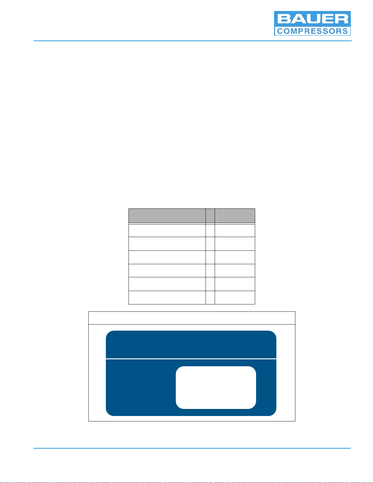
When placing an order for spare parts, please provide the following information to ensure delivery of the
correct parts. The model number, date of manufacture and serial number can be found of the compressor
unit identification plate on the compressor unit frame.
Information Example
Model Number VC 120
Serial Number 143156
Date of Manufacture 02/2013
Part Number VAL-0500
Part Description Valve
Part Quantity Required 1
Figure 1-1 Compressor Identification Label
BAUER COMPRESSORS, INC.
NORFOLK, VA 23502 U.S.A. (757) 855-6006
MODEL NO.
BLOCK NO.
SERIAL NO.
QUANTITY
MFG. DATE

Purification Systems
Page 3 3rd Edition, Rev 0 Chg 6
1.3 How to Use the Appendix
Information contained in the Appendix to this manual includes the following.
• The safety instructions applicable to this product. They must be read, understood and complied with
prior to operating the product.
• The instructions for installing this product. They must be read, understood and complied with prior to
operating the product.
• Reproducible Forms
• Reference Data
• Torque Values
• Torque Sequence
• Conversion Formulas
• Approved Lubricants
• Glossary of Abbreviations & Acronyms
• Additional Documents
^WARNING
The use of repair parts other than those included in the Bauer Replacement Parts Lists may create unsafe
conditions over which Bauer has no control. Such unsafe conditions can lead to accidents that may be life-
threatening, cause substantial bodily injury, and/or result in damage to the equipment. Therefore, Bauer
Compressors, Inc. can bear no responsibility for equipment in which unapproved repair parts are installed.
MNL-0096
April 17, 2013 Page 4
CHAPTER 2: PURIFICATION SYSTEM
2.1 Introduction
The purpose of all Bauer breathing air purification systems is to remove carbon monoxide, oil, water,
taste and odor from the compressed air stream before final delivery.
The purpose of all Bauer industrial air purification systems is to remove oil and water from the com-
pressed air stream before final delivery.
The quality of gas produced by the compressor is directly related to the quality and temperature of the gas
taken in by the unit. Intake gas should as close as possible to 50 °F (10 °C) and cleanest available and as
dry as possible. Bauer compressors normally add approximately 18 °F (10 °C) to the intake gas tempera-
ture. The purification cartridges perform their best at approximately 68 °F (20 °C). Adequate ventilation
enhances the quality and life of the purification cartridges.
2.1.1 General Purification System Procedures
1. Keep an accurate record of operating hours to ensure exact attention to maintenance intervals
2. Change all cartridges before reactivating a compressor unit that has been out of service more than
three months. Leave cartridges in the unit as long as it is out of service.
3. While out of service keep all condensate drain valves closed. Maintain a pressure of 700 - 1,100 psi
(50 to 80 bar) within the system to prevent moisture from entering the compressor and purification
system.
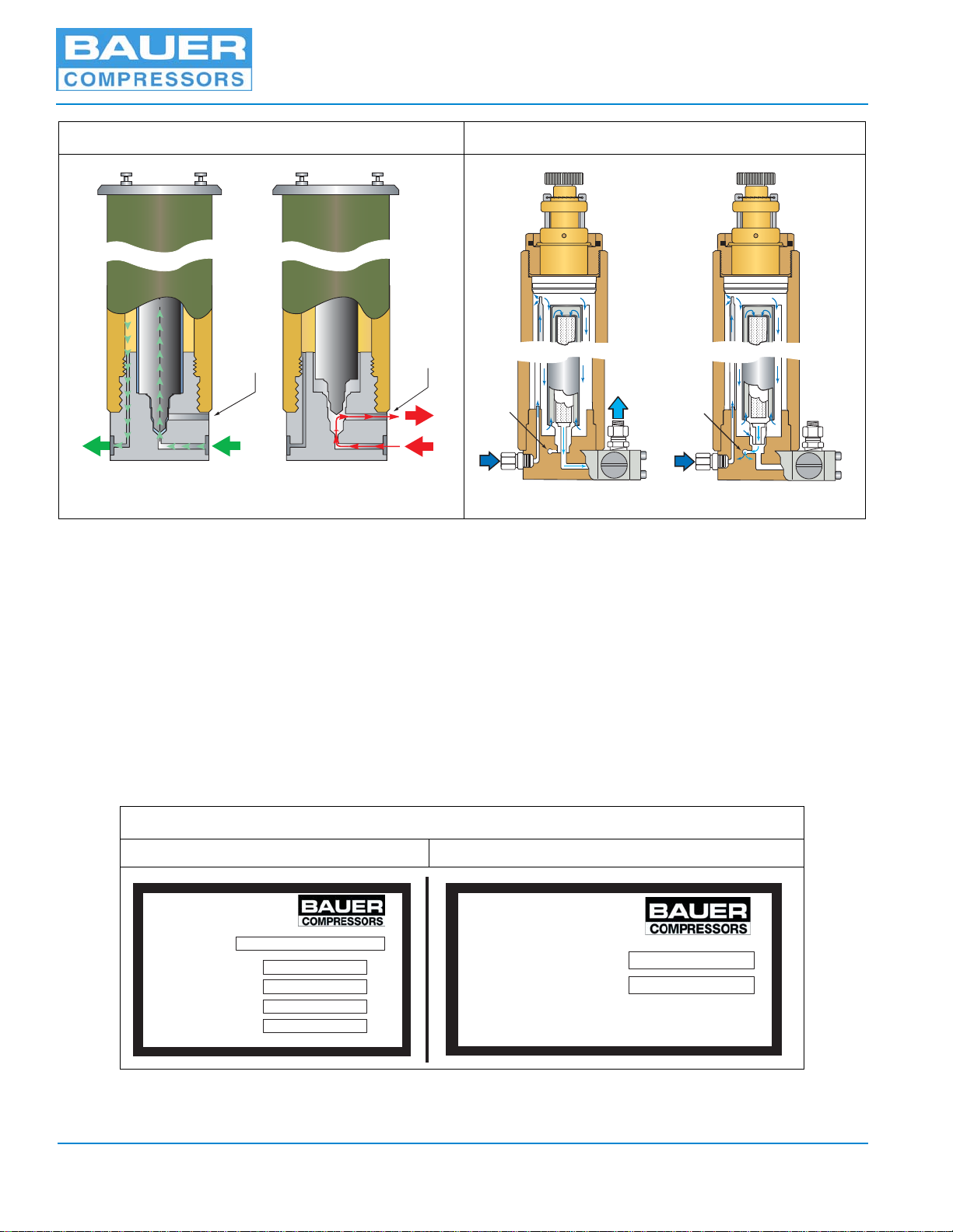
2.1.2 Chamber Safety Bore
The chambers in all Bauer purification systems are designed to prevent pressurization if the cartridge is
missing, not seated properly or damaged (Figure 2-1 & Figure 2-2). Without a cartridge properly in place
the safety bore is not sealed, the air escapes into the atmosphere, no pressure can be built up and thus it is
ensured that unfiltered air is not supplied to the consuming device. If air is escaping from the safety bore
remove and check cartridge. If necessary replace the cartridge or O-rings.
^WARNING
Industrial Air Purification System cartridges do not remove Carbon Monoxide
and must not be used in breathing air applications.
Purification Systems
Page 5 3rd Edition, Rev 0 Chg 6
2.1.3 Manual Condensate Drainage
The condensate must be drained from the oil and water separator before changing any cartridge, before
beginning each filling procedure and in the absence of an Automatic Condensate Drain (ACD) system,
every fifteen minutes during the filling procedure. This is done by slowly opening the condensate drain
valves. They are opened approximately 1/3 of a turn to the left and held open until the condensate is com-
pletely drained. The condensate drain valves close by spring pressure but if necessary may be tightened
by hand to ensure they are completely air tight.
2.1.4 Model, Serial Number and Part Number Identification
2.1.4.1 Compressor Dataplate
The model number, date of manufacture and serial number can be found on the compressor unit identifi-
cation plate in the main electrical enclosure and frame.
Figure 2-1 Cartridge Safety Venting Figure 2-2 P0 & P31 Safety Venting
Figure 2-3 Purification System Dataplates (typical)
Purification System Cartridge Installation
Safety
Vent
Cartridge Installed
correctly
Safety
Vent
No Cartridge Installed
or Installed incorrectly Cartridge Installed
Correctly No Cartridge or Installed
Incorrectly
Safety
Vent
Safety
Vent
CARTRIDGE FOR
CARTRIDGE NO.
LBL-0044
CARTRIDGE TO BE
INSTALLED
1328 Azalea Garden Road - Norfolk Virginia 23502-1944
Phone: (757) 855-6006 Fax: (757) 855-8224
MODEL NO.
MAX. PRESSURE
AIR PROCESSED
O-RING
BACK-UP RING
psig
cu. ft.
LBL-0191
PURIFICATION
SYSTEM

MNL-0096
April 17, 2013 Page 6
2.1.4.2 Purification System Dataplate
Refer to the compressor unit purification system data plate (Figure 2-3) on the compressor front to deter-
mine your purification system model and specifications.
2.1.4.3 Cartridge Installation Dataplate
The function performed by each chamber in the purification system is determined by the type of cartridge
installed in that chamber. Refer to the cartridge installation data plate on the chamber to determine the
purpose and part number of the cartridge installed in that chamber. (Figure 2-3).
2.1.5 Breathing Air Purification System Configurations
Purification System Number and Type of Cartridges Processing Capacity
Dryer Purification Securus®cubic ft (ft)3
P0 Combined 3,200
P1 … 1 … 15,000
P2 … 1 … 40,000
P2 with Securus®… … 1 67,000
P4 1 1 … 60,000
P5 1 1 … 90,000
P5 with Securus®1 … 1 150,000
P10 2 1 140,000
P10 with Securus®2 … 1 230,000
P12a
a. P12 and P14 have the Securus®Electronic Moisture Monitor System as standard equipment.
1 1 420,000
P14 a2 1 650,000
P31 Combined 11,760
P41 … 1 28,700
P41 with Securus®… … 1 47,000
P42 1 1 … 64,000
P42 with Securus®1 … 1 107,000
P43 2 1 … 100,000
P43 with Securus®2 … 1 164,000
P81 1 1 124,000
P81 with Securus®1 ... 1 198,000

Purification Systems
Page 7 3rd Edition, Rev 0 Chg 6
2.1.6 Industrial Purification System Configurations
2.1.7 Cartridge Operating Life
Every Bauer Purification System is designed to process a certain volume of air before the cartridges
require replacement. By using special test equipment that measures the quality of air at the outlet any
quality reduction may be detected. However as most compressor owners do not have this test equipment
the recommended method of determining cartridge operating life is to maintain a written record of the
volume of air processed by the purification system.
Each Bauer compressor block is rated to produce a standard volume of air per minute and by using this
number and the air processing capability of the purification system it is possible to calculate the maxi-
mum operating hours before the cartridges need to be replaced. See Paragraph 2.1.7.1 for the method of
determining this figure.
The ambient air temperature and its ability to cool the compressor will effect the operating life of the car-
tridge. See Paragraph 2.1.7.2 for the method of calculating this adjustment factor.
The optimum place to measure the temperature is at the inlet to the final separator as this best reflects the
temperature of the air as it enters the chambers. Experience has shown that this temperature is approxi-
mately 18 °F above the ambient temperature. Therefore for the purpose of calculating cartridge operating
life use the Ambient Air Temperature plus 18 °F.
A form titled Air Purification Cartridge Operating Hours is found in Paragraph 2.1.7.3 and in the
Appendices. It is used for recording the ambient temperature, operating time and adjustment factor. It
Purification System Number and Type of Cartridges Processing Capacity
Dryer Purification Securus®cubic ft (ft)3
P0 Combined 3,200
P1 … 1 … 15,000
P2 … 1 … 40,000
IP2 with Securus®… … 1 67,000
P4 1 1 … 60,000
P5 1 1 … 90,000
IP5 with Securus®1 … 1 150,000
P10 2 1 140,000
IP10 with Securus®2 … 1 230,000
P31 Combined 11,760
IP41 with Securus®… … 1 47,000
IP42 with Securus®1 … 1 107,000
IP43 with Securus®2 … 1 164,000

MNL-0096
April 17, 2013 Page 8
is suggested that it be copied, placed in a protective folder and kept with the unit to record the adjusted
operating hours. An example of how this form is used is shown in Figure 2-5.
2.1.7.1 Calculating the Maximum Cartridge Operating Hours
1. From the purification system data plate (See Figure 2-3) on the purification chamber determine the
Air Processed (cu.ft.)
2. From the paragraph titled Compressor Specifications in the instruction manual for your compressor
unit determine the Charging Rate in SCFM of your compressor.
3. Divide the Air Processed by the Charging Rate to obtain the Maximum Operating Time in minutes
4. Divide the Maximum Operating Time in minutes by 60 to obtain the Maximum Operating Hours.
5. Record the answer on the Air Purification Cartridge Operating Hours form.
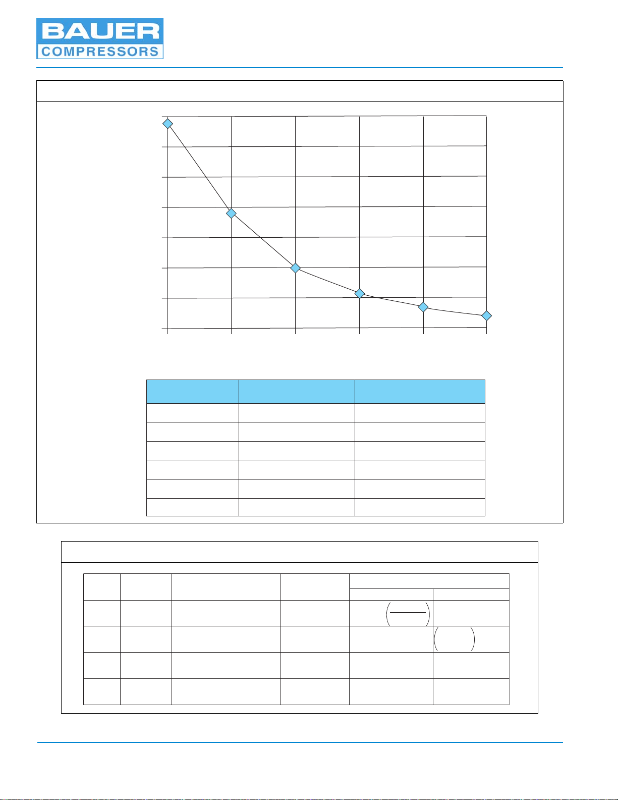
2.1.7.2 Calculating the Adjusted Cartridge Operating Hours
1. Using the Air Purification Cartridge Operating Hours form record the Date, Operating Hours and
Ambient Air Temperature plus 18 °F.
2. Using either the graph or the chart in Figure 2-4 determine the Correction Factor.
3. Divide the Operating Hours by the Correction Factor and record it under the column labeled Today.
4. Add the hours recorded in Today to the previous Total and record it as the current Total.
5. When the Total approaches the Maximum Operating Hours replace the Cartridges.
Purification Systems
Page 9 3rd Edition, Rev 0 Chg 6
Figure 2-4 Correction Factor for Cartridge Operating Hours
Figure 2-5 Example Record of Adjusted Operating Hours
°F
[°C x 9/5 +32]
°C
[(°F - 32) x 5/9]Correction Factor
50 122 0.21
40 104 0.34
30 860.58
20 681.00
10 50 1.81
032 3.44
0.0
0.5
1.0
1.5
2.0
2.5
3.0
3.5
0 °C 10 °C 20 °C 30 °C 40 °C 50 °C
Conversion Factor
32 °F 50 °F 68°F 86 °F 104 °F 122 °F
Date Operating
Hours Ambient Temp.
during Compression +18 °F Correction
Factor Adjusted Cartridge Hours
Today Total
10/19/04 8 92°F
(33 °C)
0.5 16.00 16.00
11/01/04 4 45°F
(7.2 °C)
2.25 1.78 17.78
Op hrs
Corr. factor
Total hrs
+Today hrs

MNL-0096
April 17, 2013 Page 10
2.1.7.3 Air Purification Cartridge Operating Hours Form
Date Operating
hours Ambient temp. + 18°F
during compression Correction
factor Adjusted cartridge hours
Today Total

Purification Systems
Page 11 3rd Edition, Rev 0 Chg 6
CHAPTER 3: SINGLE CHAMBER PURIFICATION SYSTEMS
3.1 Applicability
This chapter applies to Bauer Purification Systems P0 and P31 Only.
3.2 P0 Purification System Description
The P0 Purification System consists of a separator and a cartridge chamber. In the separator surround-
ing the cartridge chamber, liquid oil and water particles are separated from the compressed air by a pipe
nozzle. Residual oil and water particles are then removed by the filter cartridge and the air leaving the
P0 Purification System is free of water, oil, taste and smell.
Figure 3-1 P0 Purification Chamber
1. Inlet Connection
2. Condensate Drain Connection
3. Condensate Drain Valve
4. Bleed Port
5. Bleed Valve
6. Pressure Maintaining Valve
7. Outlet Connection
8. Safety Valve
1
2
345
6
7
8

MNL-0096
April 17, 2013 Page 12
3.2.1 Maintenance
3.2.1.1 Replacing the Cartridge
See Figure 3-2
1. Depressurize system before starting any maintenance, by opening the condensate drain valve and
bleed valve.
2. Unscrew plug (5) on top of the housing (4).
3. Extract old cartridge. (2)
4. Dry inside of the housing (4) with a clean cloth. Check for corrosion. Replace if necessary.
5. Lubricate all threads and O-rings on both the Plug (5) and the Cartridge (2) with petroleum jelly.
6. Insert new cartridge and secure in place with plug (5).
Figure 3-2 P0 Purification System Cross Section
1. Inlet
2. Cartridge
3. Jet Pipe
4. Housing
5. Plug
6. Final Pressure Safety Valve
7. Adjustment Knob
8. Separator Chamber
9. Outlet
10. Pressure Maintaining Valve
11. Bottom
1
11
2
3
4
5
6
7
8
9
10
Cartridge Removal
Purification Systems
Page 13 3rd Edition, Rev 0 Chg 6
3.2.1.2 Chamber Replacement Interval
The maximum number of load cycles for the P0 Purification Assembly is 45,000 if operated at 5,000 psi
(300 bar) or 63,000 if operated at 3,200 psi (225 bar).
If the number of load cycles of four per hour (i.e. the condensate is drained every fifteen minutes) is not
exceeded then the maximum number of operating hours before the P0 Purification System must be
replaced is 11,125 hours at 5,000 psi (300 bar). To avoid exceeding the maximum number of load cycles
the operating hours should always be recorded.
NOTICE
The used filter cartridge must be disposed of in accordance with local regulations.
^WARNING
The P0 Purification System is subject to dynamic loading. It is designed for a certain number of load
cycles. A load cycle equates to an abrupt pressure loss caused by draining the condensate.
The P0 Purification System must be replaced after reaching the maximum number of load cycles, other-
wise the housing may fail due to material fatigue.
This manual suits for next models
26
Table of contents


