BBV Starcard User manual

Installation Guide
Starcard
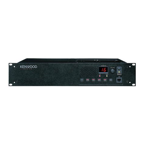
RS422/485 Star Repeater
BBV
Version 27.5


STOP AND READ
BEFORE INSTALLING!
As 3rd party protocols are not under the control of BBV,
we cannot guarantee that this unit will provide the exact
functionality required.
It is strongly recommended that operation is confirmed
during prebuild testing before installing on site.
Please contact our customer support department
if you have any questions/issues:
Tel: ++ 44 (0) 1323 444600
Email: support@bbvcctv.com
DISCLAIMER:
BBV are not liable for any errors within this manual. If you nd an error,
please let us know immediately.

Scan for a quick tour of the BBV website:
www.bbvcctv.com

Contents
Pre-Installation Checks and Procedures 6
Technical Specification 7
Introduction 7
Menu Information 8
Internal View of Starcard Showing Switch Settings 9
2 Wire Half-Duplex Mode 10
4 Wire Full-Duplex Mode 11
Cascaded Starcards 12
Daisy Chained Starcards 13
2 Wire Connection Details 14
RS485 Connection Details 15
Matrix and Receiver Setup 16
BBV Product List 18 - 19

6
Pre-Installation Checks and Procedures
Unpacking
Check packaging - Upon taking delivery of the unit, inspect the packaging for signs of damage. If damage has occurred,
advise the carriers and/or the suppliers immediately.
Check Contents - Upon taking delivery of the unit, unpack the receiver carefully and check that all the items are present and
correct. If any items are missing or damaged, contact your equipment dealer.
Retain Packaging - The shipping carton is the safest container in which to transport the unit. Retain undamaged packaging
for possible future use.
Important Safety Precautions
Read Instructions - All relevant safety, installation and operating instructions should be read before attempting to install,
connect or operate the unit.
Retain Instructions - All safety, installation and operating instructions should be retained for future reference.
Heed Warnings - All warnings on the unit and in any relevant safety, installation or operating instructions should be
adhered to.
Cleaning - Unplug the unit from the power outlet before cleaning. Do not use liquid cleaners or aerosol cleaners. Use a
damp cloth for cleaning.
Attachments - Do not use attachments not recommended by the product manufacturer as they may cause hazards.
Water and Moisture - Do not expose the internal electronics of this unit to water or dampness; for example, in an unprotected
outdoor installation, or in any area classied as a wet location.
Accessories - Do not attach this unit to an unstable stand, bracket or mount. The unit may fall, causing serious injury to a
person and serious damage to the unit.
Power Sources - This unit should be operated only from the type of power source indicated on the manufacturer’s label. If
you are not sure of the type of power supply you intend to use, consult your equipment dealer or local power company. For
units intended to operate from battery power or other sources, refer to operating instructions.
Overloading - Do not overload outlets and extension cords, as this can result in re or electric shock.
Object and liquid entry – Never push objects of any kind into the unit, as they may touch dangerous voltage points or short
out parts that could result in re or electric shock. Never spill liquid of any kind on or inside the unit.
Servicing – Servicing of the unit should only be undertaken by qualied service personnel, as opening or removing covers
may expose you to dangerous voltages or other hazards.
Damage Requiring Service – Servicing by qualied personnel should be carried out under the following conditions:
(a) When the power supply cord or plug is damaged.
(b) If liquid ha been spilled, or objects have fallen into the unit.
(c) If the unit does not operate normally by following the operating instructions.
(d) If the unit has been dropped or the enclosure is damaged.
(e) If the unit indicates a distinct change in performance.
Replacement Parts – If replacement parts are required, ensure that only replacement parts recommended by the product
manufacturer are used.
Safety Check – Upon completion of any service or repairs to the unit, safety checks should be performed to ensure that the
unit is in proper operating condition.
Adhere to safety standards – All normal safety precautions as laid down by British Standards and the Health and Safety at
Work Act should be observed.
WARNING
TO PREVENT DANGER OF FIRE OR SHOCK, DO NOT EXPOSE THE INTERNAL COMPONENTS OF THIS EQUIPMENT TO
RAIN OR MOISTURE.

7
Technical Specification
Power Requirements 12Vdc 1000mA
Inputs 2 or 4 wire RS485 (switch selectable)
Outputs 8 x 2 or 4 wire RS485/422 (switch selectable – DEFAULT 4 WIRE)
Maximum cable run approx. 4000 Feet/1200M
Facilities LED as power and data indication
Other Outputs RS232 monitor output via chassis mounted DB9 connector
Boxed Dimensions Available to mount in BBV TX1500 sub rack or tted in 19” 1 U rack 100mm deep rack
mountable case
Options A Starcard can be converted to a Starcard Converter by purchasing a unique unlock code - this can
be done instantaneously when in-the-eld. Please contact our technical support team for assistance.
Please refer to the additional Starcard Converter addendum for details.
Introduction
General
The RS485/422 Starcard is designed to simplify the installation of RS485/422 telemetry systems.
Eight individual outputs are provided. Each output can be connected to a single dome/receiver or up to 32 domes/receivers
wired as a daisy chain. When the domes/receivers are wired as a daisy chain, the last unit’s RS485/422 must be terminated and
the intermediate units must be un-terminated. With a single dome connected to each output, the RS485/422 must be terminated.
The Starcard can be used with either 2 wire, half duplex; 4 wire, full duplex or simplex systems.
It has been tested with the Panasonic FS616 multiplexer in 2 and 4 wire modes and with the SX350 video matrix in 2 wire mode.
The Starcard can also be used with simplex RS485/422 links, for example the RS485 output of DM System Sprite and Digital
Sprite range of multiplexers, Integral Technologies DVX range amongst others.
The Starcard is not protocol independent and will work at up to 19200 baud. It is recommended that when used with extended
cable distances and/or noisy environments 9600 baud is used to prevent control problems.
A RS232 serial output is provided via a DB9F to aid with diagnostic and trouble shooting.
What is 2 wire and 4 wire
2 wire is used with half duplex (command and response) systems. Generally telemetry uses simplex telemetry, i.e. command
only. In this case the Starcard will be set to 4 wire. This allows use with both simplex (using 2 wire) or full duplex (using 4 wire)
systems. Unless you are using a known half duplex, 2 wire, system then set the Starcard to 4 wire.
The following pages showing wiring details when used in 2 and 4 wire systems.
Manual Version
V27.5

8
Menu Information
On power up or pressing the middle button the screen will display:
The specic device number
Space to enter you unlock password (to transform the Starcard into a Starcard Converter)
Status locked (this will change to ‘unlocked’ when the Starcard is transformed into a Starcard Converter)
Data Type ( 2 wire or 4 wire)
To enter a new password, use the middle button to scroll through the menu and then use the right and left
buttons to change the password digits.
Right & Select in menu
Down & Open in menu
Left
STARCARD
0 0 0 1 V0.3
Starcard
Enter pin
Device xxxx
Password 0000 Enter
Status locked
Data Type 4 wire
Exit
0 0 0 1 V0.3
Starcard
Enter pin
Device xxxx
Password 0000 Enter
Status locked
Data Type 4 wire
Exit
Press the ‘right’ button when the mode type is ashing to switch between 4 wire and 2 wire.
Please refer to your chosen protocol to see whether it is 4 wire or 2 wire.
Enter pin
Device xxxx
Password 0000 Enter
Status locked
Data Type 2 wire
Exit

9
Starcard PCB Switches
SW1 - RS485 line termination for outputs 1 - 4 ON = termination ON (default)
SW1/1 & 1/2 = Output 1 termination
SW1/1 & 1/2 = Output 2 termination
SW1/1 & 1/2 = Output 3 termination
SW1/1 & 1/2 = Output 4 termination
SW2 - RS485 line termination for outputs 5 - 8 ON = termination ON (default)
SW2/1 & 2/2 = Output 5 termination
SW2/3 & 2/4 = Output 6 termination
SW2/5 & 2/6 = Output 7 termination
SW2/7 & 2/8 = Output 8 termination
SW3 - RS485 input line termination ON = termination ON (default)
Internal View of Starcard Showing Switch Settings
1 2 3 4 5 6 7 8
1 2 3 4 5 6 7 8
SW1 setting showing
termination ON
SW2 setting showing
termination ON
SW1 SW2
SW3

10
TRB -
TRA +
TRB -
TRA +
TRB -
TRA +
TRB -
TRA +
TRB -
TRA +
TRB -
TRA +
TRB -
TRA +
2 Wire Half-Duplex Mode
Data IN:
RS485 or RS422 Simplex Data IN to MASTER RA/RB or BBV TELEMETRY IN from TX1500 or FBM.
Data OUT:
Data OUT to domes on STAR outputs TRA/TRB.
Star n
Close up view showing RS485 connection into and out of the Starcard
MASTER
Data OUT
TRB -
TRA +
RA +
RA -
Data IN
TTG
RRRRN
BAABD
TTG
RRRRN
BAABD
Frame ground
To dome RB(-)/TRB
To dome RB(+)/TRA
RS485 network length maximum 1200m per output.
Please remember to terminate the last
dome of each output.
2 wire RS485 notes
1. Ensure that the dome/receiver is set for 2 wire
telemetry, half-duplex.
2. The controller must be set for 2 wire using either a
rear panel switch or menu access. Half-duplex must
be selected from within the setup menu.
3. Baud rates for the controller and dome/receivers
must be the same. It is advisable to use 9600 baud
to reduce the possibility of corrupted data causing
intermittent control.
Panasonic specific notes
• FS616 - A single RS485 output is available. Connect
the RS485 output to the Starcard as shown.
• SX350 - Two RS485 outputs are available.
• SX550/850 - Not required as each matrix RS485
output card has eight individual outputs.
Frame ground
From controller TB(-)
From controller TA(+)

11
TRB -
TRA +
TRB -
TRA +
TRB -
TRA +
TRB -
TRA +
TRB -
TRA +
TRB -
TRA +
TRB -
TRA +
4 Wire Full-Duplex Mode
Data IN:
RS485 or RS422 Simplex Data IN to MASTER RA/RB or BBV TELEMETRY IN from TX1500 or FBM.
Data OUT:
Data OUT to domes on STAR outputs TRA/TRB.
Star n
Close up view showing RS422 connection into and out of the Starcard
MASTER
Data OUT
TRB -
TRA +
RA +
RA -
Data IN
TTG
RRRRN
BAABD
TTG
RRRRN
BAABD
RS485 network length maximum 1200m per output.
Please remember to terminate the last
dome of each output.
4 wire RS422 notes
1. Ensure that the dome/receiver is set for 4 wire
telemetry, full-duplex.
2. The controller must be set for 4 wire using either a
rear panel switch or menu access. Full-duplex must
be selected from within the setup menu.
3. Baud rates for the controller and dome/receivers
must be the same. It is advisable to use 9600 baud
to reduce the possibility of corrupted data causing
intermittent control.
Panasonic specific notes
• FS616 - A single RS485 output is available. Connect
the RS485 output to the Starcard as shown.
• SX350 - Not compatible with 4 wire telemetry.
• SX550/850 - Not required as each matrix RS485
output card has eight individual outputs.
Frame ground
To controller RB(-)
To controller RA(+)
From controller TA(+)
From controller TB(-)
Frame ground
To dome RB(-)
To dome RA(+)
From dome TA(+)
From dome TB(-)

12
Cascaded Starcards
RS422/485 to domes/receivers RS422/485 to domes/receivers RS422/485 to domes/receivers
Starcards can be cascaded to suit each installation
1200m Maximum per leg
Control System

13
Daisy Chained Starcards
RS485 to domes/receivers RS485 to domes/receivers RS485 to domes/receivers
On single direction RS485, multiple Starcards can be daisy chained to provide multiple outputs.
1200m Maximum per leg
Control System
Starcard SW3
setting RS485
unterminated
4 WIRE
1 2
ON Starcard SW3
setting RS485
unterminated
4 WIRE
Starcard SW3
setting RS485
terminated
4 WIRE
1 2 1 2
ON ON

14
KEY
RS485
Coax
BBV RS485 Starcard
Camera 1 DC Head
Rx55X Address 1
Camera 2 AC Head
Rx45X Address 2
Camera 3 DC Head
Rx55X Address 3
2 Wire Connection Details
Dome
Rx45X / Rx55X
O Y
R G E B
A R L R
R N E L O
E G E O W
D E N W N
TTG
RRNRR
ABDAB
R R T T G
BARRN
ABD
R R T T G
BARRN
ABD
SCREEN
SCREEN

15
KEY
RS485
Coax
BBV RS485 Starcard in
CONVERTER MODE
Dome
Rx45X / Rx55X
Camera 1 DC Head
Rx55X Address 1
Camera 2 AC Head
Rx45X Address 2
Camera 3 DC Head
Rx55X Address 3
A B
OR OR
+ -
R R T T G
BARRN
ABD
R R T T G
BARRN
ABD
RS485 Connection Details
(Starcard must be in 4 wire mode)
TTG
RRNRR
ABDAB

16
Rx45X
Rx45X
Fixed Speed, P/T Zoom/Focus, 32 Preset with 3 Aux, 8 local alarms
Rx45X Rx45X Rx45X
Rx55X
High & Variable speed, P/T Zoom/Focus, 32 Preset with 3 Aux, 8 local alarms
Rx45X Rx45X
Matrix and Receiver Setup
KEY
CAT 5
Fibre
Cable
NVT Interface
Fibre Interface

17
Notes

18
Tx1000 MK2
The Tx1000 MK2 series combines
a video switch with the simplicity
of installation associated with coax
controlled systems.
Tx1500
The Tx1500 series combines a
state-of-the-art-video matrix with the
simplicity of installation associated
with coax controlled systems.
BBV Product List
All of the BBV products are available to view and purchase online: www.bbvcctv.com
FBM
Available with up to 64 monitor
outputs and 512 video channels.
Starcard
The Starcard provides a simple
and cost-effective solution in
the installation of RS485/422
telemetry systems.
Starcard Converter
The Starcard Converter is
designed to provide simple
and cost effective RS485/422
protocol conversion.

19
Coax Converter 1
This is a direct replacement for the
old Rx10X. Multi Protocol Dome
Interface Receiver 12-24Vac/dc. A
simple solution to control one of a
variety of 3rd Party Dome Cameras.
BBV Product List
All of the BBV products are available to view and purchase online: www.bbvcctv.com
Rx25X
The Rx25X Multiple Protocol Auxiliary
Relay Receiver is designed to offer
a simple, cost effective solution to
activate an auxiliary output.
Rx55X/WBX
Advanced Multiple Protocol
DC Receiver.
ASGARD HD Decoder
The Asgard HD Decoder is a 30fps,
1080p standalone unit, which
facilitates the streaming of camera
images from one or more media
servers, without the need of a PC.

Table of contents
