BD Sensors KL 1 User manual
BD SENSORS GmbH
BD-Sensors-Straße 1 Telefon +49 (0) 92 35 / 98 11- 0 www.bdsensors.de
D - 95199 Thierstein Telefax +49 (0) 92 35 / 98 11- 11 info@bdsensors.de
Operating Manual
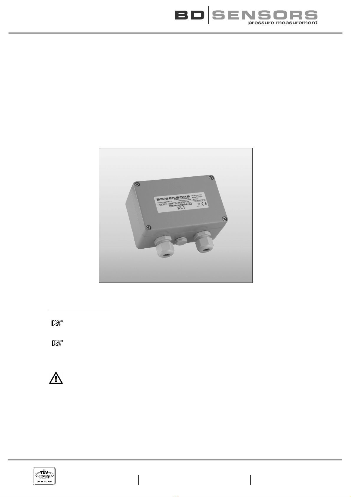
Terminal Box KL 1
Important notes:
Please read this operating manual carefully before installation and start- up
of the terminal box.
This operating manual must be kept at an accessible location for further
use.
The device may only be installed, used and serviced by persons who are
familiar with this operating manual as well as with the applicable regulations
on occupational safety and accident prevention.

2
KL 1
pressure measurement
1. General
1.1 Information on the intended use
•The terminal box KL 1 is intended for the professional electrical connection of 2-wire
transmitters. It offers integrated atmospheric pressure compensation. Optionally
equipped with overvoltage protection and Pt 100 transmitter for BD SENSORS de-
vices.
•The terminal box KL 1 is equipped with a pressure balance item for equalization of
atmospheric reference. Caused by this on the supply side a cable without ventilation
tube can be used.
•Vertical terminal clamps enable easy connection of cables inside. The terminal box
has to be mounting via two fastening screws.
•The device shall be used according to the area of application specified above!
•No liability is assumed and warranty claims are excluded in case of improper applica-
tion, modification or damage to the device.
1.2 Target group
This operating manual is intended for qualified technical personnel.
1.3 Symbols used
: Caution : Note
1.4 Safety notes
The following notes must be observed to avoid hazards for the operator and his
environment:
The device may only be installed, used and serviced by persons familiar with this
operating manual!
Applicable regulations regarding occupational safety, accident prevention and national
installation standards must be complied with!
The product must only be used within the specifications! (compare the technical data
under “Appendix“)
Mount the device in the currentless condition!
1.5 Package contents
Please verify that all listed parts are included in the delivery and check consistency with the
order:
•Terminal Box KL 1
•Operating manual "KL 1"
3 www.bdsensors.de
KL 1
2. Product identification
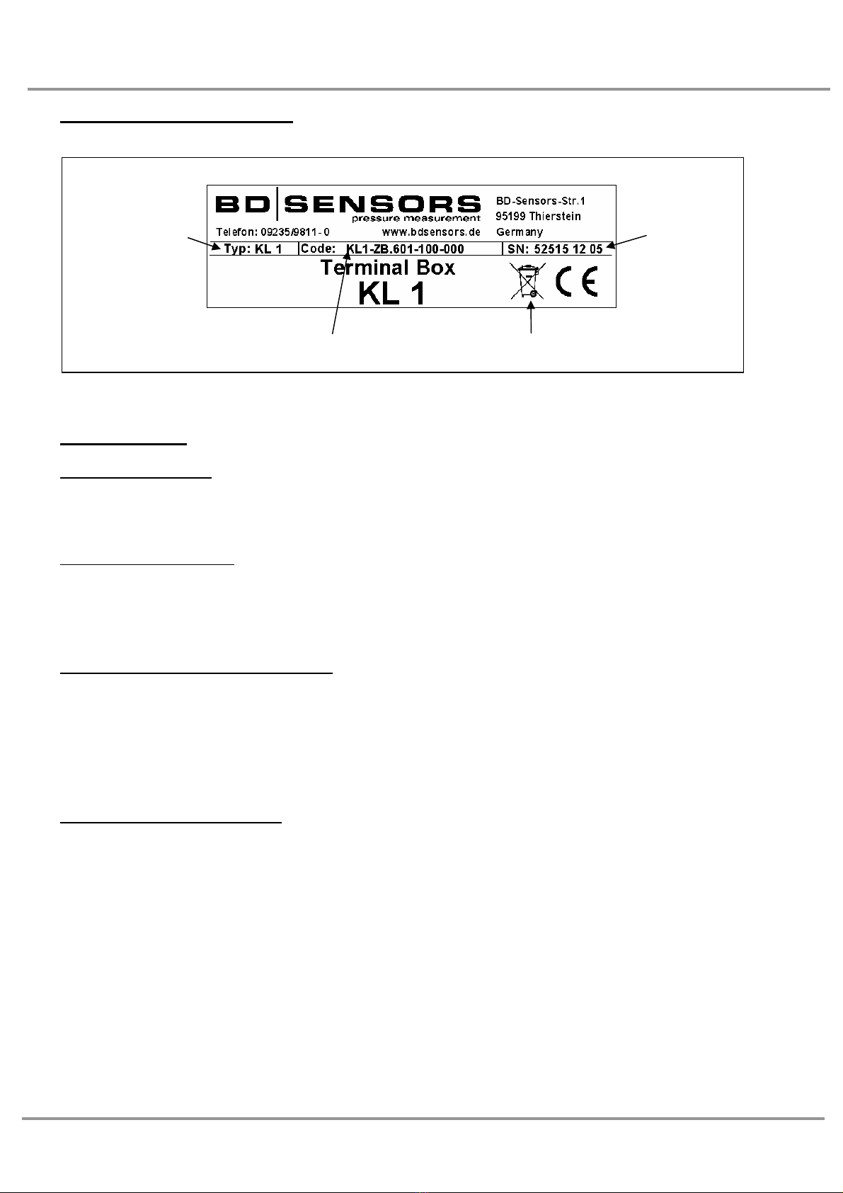
The device can be identified by its type plate. It provides the most important data.
Fig. 1 Type plate
3. Installation
3.1 General notes
•Do not use any force when installing the device!
•Handle the terminal box carefully and properly to avoid any damages.
3.2 Installation steps
•Carefully remove the terminal box from the package.
•Mount the terminal box stationary on a suitable fixing location via two appropriated
fastening screws.
3.3 Lead in the transmitter cable
•Lead in the connecting cable of the transmitter through the cable gland on the left
side. The cable length inside the terminal box has to be long enough for connecting
the cords with the terminal clamps on the left (transmitter).
•Next tighten the cable gland by hand. Take care that the cable is strain-relieved.
•Pay attention that the PTFE-filter on the gauge reference is not damaged or removed.
3.4 Lead in the supply line
•Lead in the supply line through the cable gland on the right side. The cable length in-
side the terminal box has to be long enough for connecting the cords with the terminal
clamps on the right (supply).
•Next tighten the cable gland by hand. Take care that the cable is strain-relieved.
Type
designation
Serial
number
Ordering code Disposal note
4
KL 1
pressure measurement
3.5 Electrical installation
Open the top cover; establish the electrical connection of the device according to the follow-
ing table and the wiring diagram. Screw on the top cover on the box again.
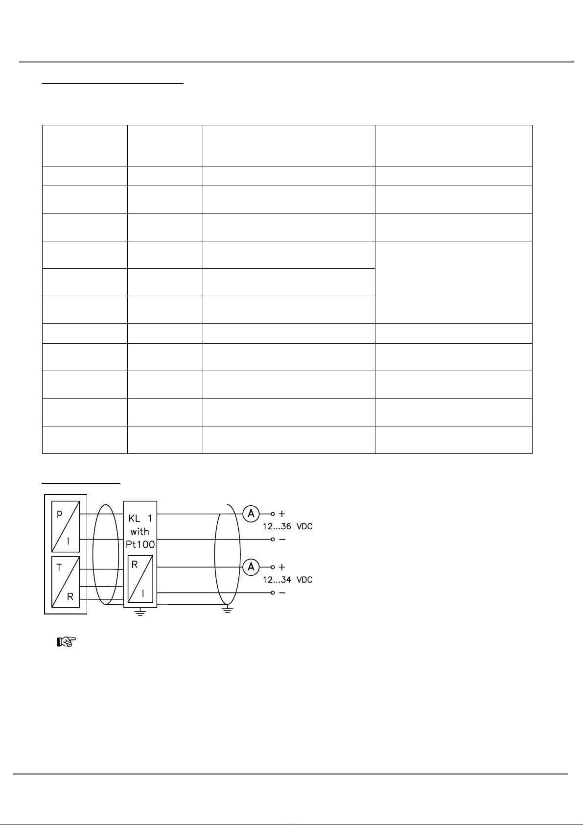
Designation
Terminal
block
Electrical connection
and cable colours of
BD SENSORS transmitters
Has to be connected with
GND transmitter ground clamp (yellow / green) cable shield of transmitter
VB- transmitter supply - (brown) neg. connecting cable of
transmitter
VB+ transmitter suppy + (white) pos. connecting cable of
transmitter
T+ transmitter
(optional) temperature + (yellow)
T- transmitter
(optional) temperature - (grey)
T- transmitter
(optional) temperature - (pink)
connecting cable for Pt 100-
sensor of the BD SENSORS
transmitter (connection
according to 3-wire-method)
GND supply ground clamp cable shield of supply line
VT - supply supply - neg. signal line for
temperature signal
VT + supply supply + pos. signal line for
temperature signal
VP + supply supply + pos. signal line for pressure
signal
VP - supply supply - neg. signal line for pressure
signal
Wiring diagram
The ground wires of all components have to be connected!
Pressure signal
Supply +
Supply -
Temp. signal
Supply +
Supply -
5 www.bdsensors.de
KL 1
3.6 Option overvoltage protection
•With optionally overvoltage protection additionally a solid conductor with a minimal
cross section of 4 mm2has to be connected with the external ground clamp.
•Besides it also has to be connect with a suitable grounding (earth bus bar;
equipotential bonding)
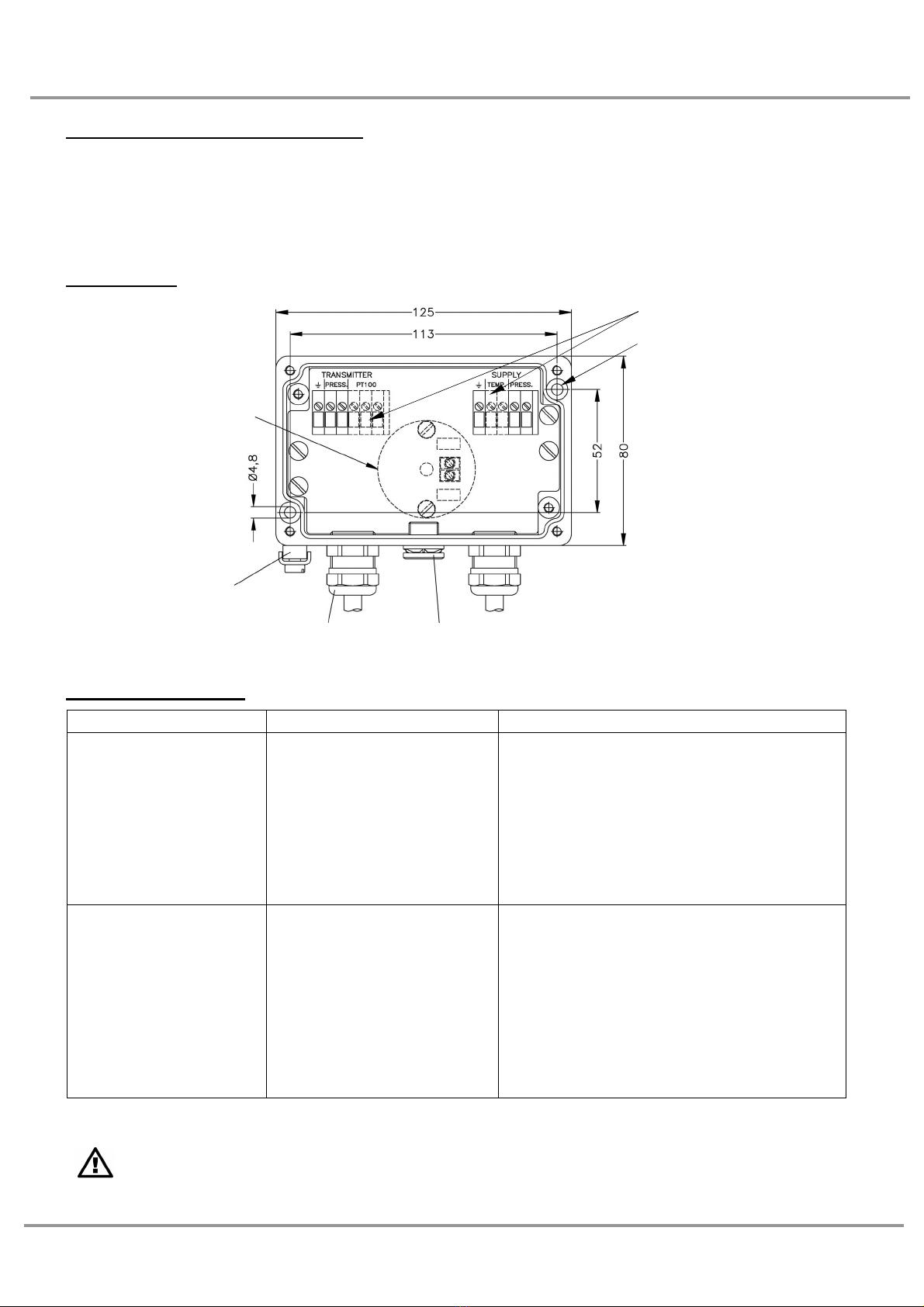
3.7 Drawing
4. Error handling
Malfunction Possible cause Error detection / corrective
changing measuring
value with varying air
pressure and con-
stant filling level
(gauge measure-
ment)
- pressure balance item is
contaminated, clogged
or damaged
- Check the pressure balance item. Is
the described cause correct, the
device should be placed out of service
according to regulations and the pres-
sure balance item has to be replaced.
The pressure balance item can be
ordered from BD SENSORS as spare
part.
broken signal current
(pressure or tempera-
ture) or signal current
not identifiable
- responded overvoltage
protection and destruc-
tion of it (by overloading
the overvoltage pro-
tection also further
components can be
destroyed)
- released signal wire
- defective transmitter
- please send the device to
BD·SENSORS for repair
- tighten the signal wire again
- replace the transmitter
If a different malfunction occurs please send it to our service address for repair.
Repairs on the terminal box may only be performed by the manufacturer!
external ground clamp
4 mm² (optional)
Pt 100-transmitter
(optional)
GND VB−VB+ T+ T−T−GND VT−VT+ VP+ VP−
Cable gland
M16x1.5
Pressure balance item
Mounting hole ∅4.8
equipped only with
Pt 100 version
6
KL 1
pressure measurement
5. Placing out of service
If you want to dismantle the device, this must always be done in currentless condition!
6. Service
This device is maintenance-free.
If desired, the device can be cleaned using non-aggressive cleaning solutions.
7. Repair
Please return the device to BD SENSORS for repair if you encounter malfunctions that can-
not be remedied. We will do our best to process all repairs as quickly as possible. Apart from
the defective device, we will need you to provide us with a detailed error description. You
should include this directly with the device.
Our service address:
BD SENSORS GmbH
Serviceabteilung
BD-Sensors-Str. 1
95199 Thierstein
Germany
8. Disposal
The device must be disposed according to the European Directives
2002/96/EC and 2003/108/EC (on waste electrical and electronic
equipment). Waste of electrical and electronic equipment must not be
disposed by domestic refuse.
9. Warranty conditions
The warranty conditions are subject to the legal warranty period of 24 months from the date of
delivery. All warranty claims become void in case of improper use, modifications or damages to
the device. Likewise, there is no claim for warranty services if the defects have developed as a
result of normal wear.

7 www.bdsensors.de
KL 1
10. Appendix
General
Number of signal lines 2-wire (4 ... 20 mA) / VS= 12 … 36 VDC
Housing aluminium die cast case, grey powder-coated
Ingress protection IP 66
Cable entries cable gland M16x1.5 Polyamide, seals NBR, IP 68,
diameter range: standard 5 ... 10 mm, others on request
Atmospheric pressure
compensation
pressure compensation element with PTFE filter
Terminal clamps vertical clamps for stranded and solid wires up to 2.5 mm2
Weight approx. 550 g
Option overvoltage protection
Series resistance 10 Ωfor each wire
Nominal discharge
current 10 kA (8/20 µs)
Max. rated current 30 mA
Connection via external ground clamp 4 mm2
Optional Pt 100 temperature sensor
Temperature range
Standard: 0 ... 70 °C
Option: Tmin ... Tmax can be in range from -40 °C up to 400 °C
Connection
temperature sensor 3-wire
Output signal /
Supply 2-wire: 4 … 20 mA / VS= 12 … 34 VDC
Accuracy < 0.15 %
Linearity < 0.1 %
Thermal error < 0.01 % / K

8
KL 1
pressure measurement
BD SENSORS GmbH
BD-Sensors-Str. 1
95199 Thierstein
Germany
Phone +49 (0) 92 35 / 98 11- 0
Fax +49 (0) 92 35 / 98 11- 11
The addresses of our agencies abroad are listed on our homepage www.bdsensors.com.
There you can also download data sheets, operating manuals, ordering codes and certifi-
cates.
further agencies in:
•Australia •Kazackstan
•China •Russia
•Iran •Taiwan
•Israel •Thailand
The contents of this operating manual reflect the version available at the time of printing. It
has been prepared to the best knowledge and belief. However, errors may still be encoun-
tered. For incorrect statements and its consequence we can not assume liability.
– Technical modifications reserved –
EX_KL1_E_140306
Telefon +49 (0) 92 35 / 98 11- 0 www.bdsensors.de
Telefax +49 (0) 92 35 / 98 11- 11 info@bdsensors.de
Table of contents
Popular Industrial Electrical manuals by other brands


centor
centor ARES Basic III Guard Tour Verification... manual

Vertiv
Vertiv Liebert Maintenance Bypass Cabinet Installer/user guide

GARO
GARO Nova GTC Assembly instructions / End User Instruction

Cooper
Cooper S285-90-1 Installation, operation and maintenance instructions

Sterling Power Products
Sterling Power Products BAL24 Handbook

Murata
Murata GRM155R71H222MA01 Series Reference sheet


