GARO Nova GTC User manual

GARO AB
GARO Nova GTC
Box 203, SE–335 25 Gnosjö
Phone: +46 (0) 370 33 28 00
garo.se
Manual 380234 1.0
Assembly instructions / End User Instruction (EN)
EN

TABLE OF CONTENT
About this manual 3
INFORMATION 3
Warnings 3
Cautions 4
Notes 4
INSTALLATION OF STANDALONE GTC NOVA 5
RFID reader installation 8
RFID settings for stand alone GTC Nova 9
Dimensional sketch 10
USER MANUAL 11
Normal use / Charging 11
Resetting/Conditioning of RCCB 12
Electrical diagram 13
Connecting to GTC Nova Wifi access point (AP) 16
Web interface 17
Main menu 17
Energy information 19
RFID settings in the web interface 20
Schedule 20
Connect GTC Nova to a local network via Wi-Fi 21
Connect GTC Nova to a local network via ethernet with DHCP 21
Connect GTC Nova to a local network via ethernet using static IP-adress 22
Factory reset of Network settings 22
Updating the firmware 22
Uppdatering för GTC laddbox som ej är ansluten till internet via wifi eller LAN (kräver installerad wifimodul) 23
Care 23
Troubleshooting 24
Technical specifications 25
2
EN

INFORMATION
Warnings
Latest manual can always be found at
http://garoemobility.com/support
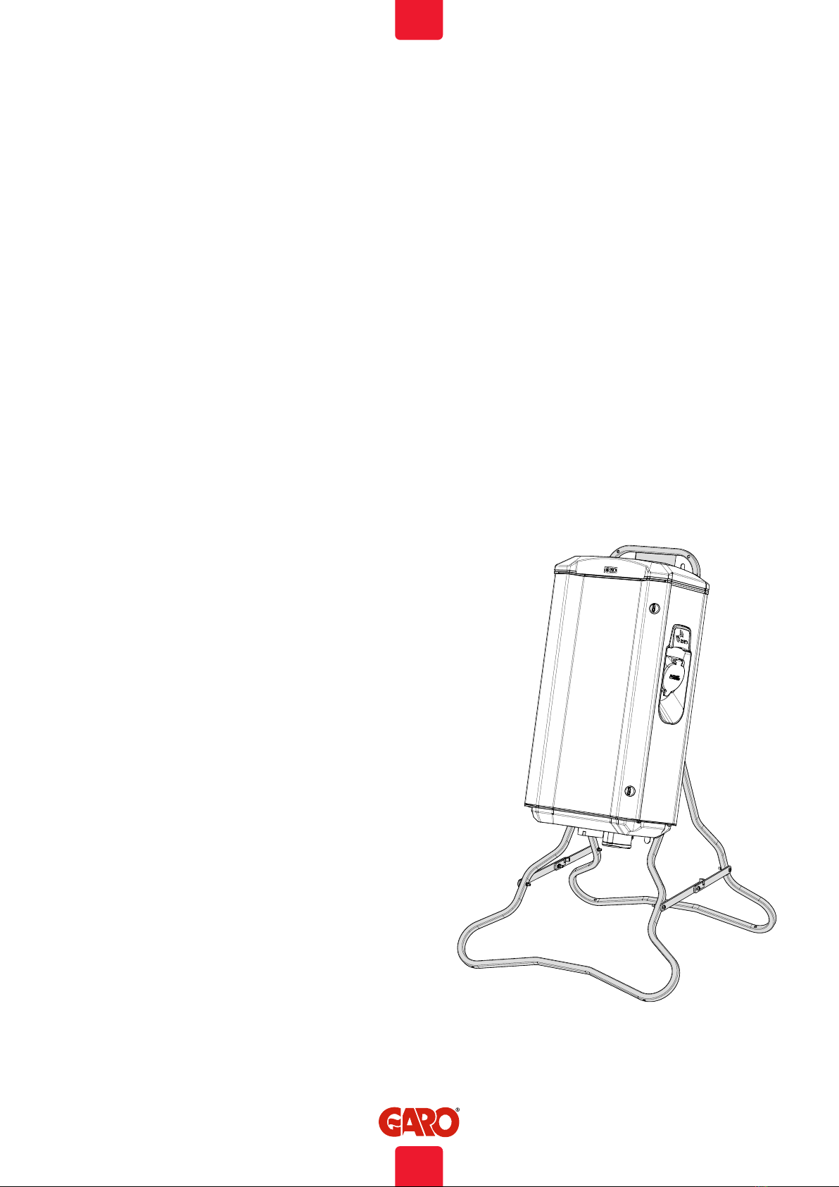
GARO GTC assortment is a range of portable EVSE stations for
Mode-3 AC charging.
Below are some example of standard features:
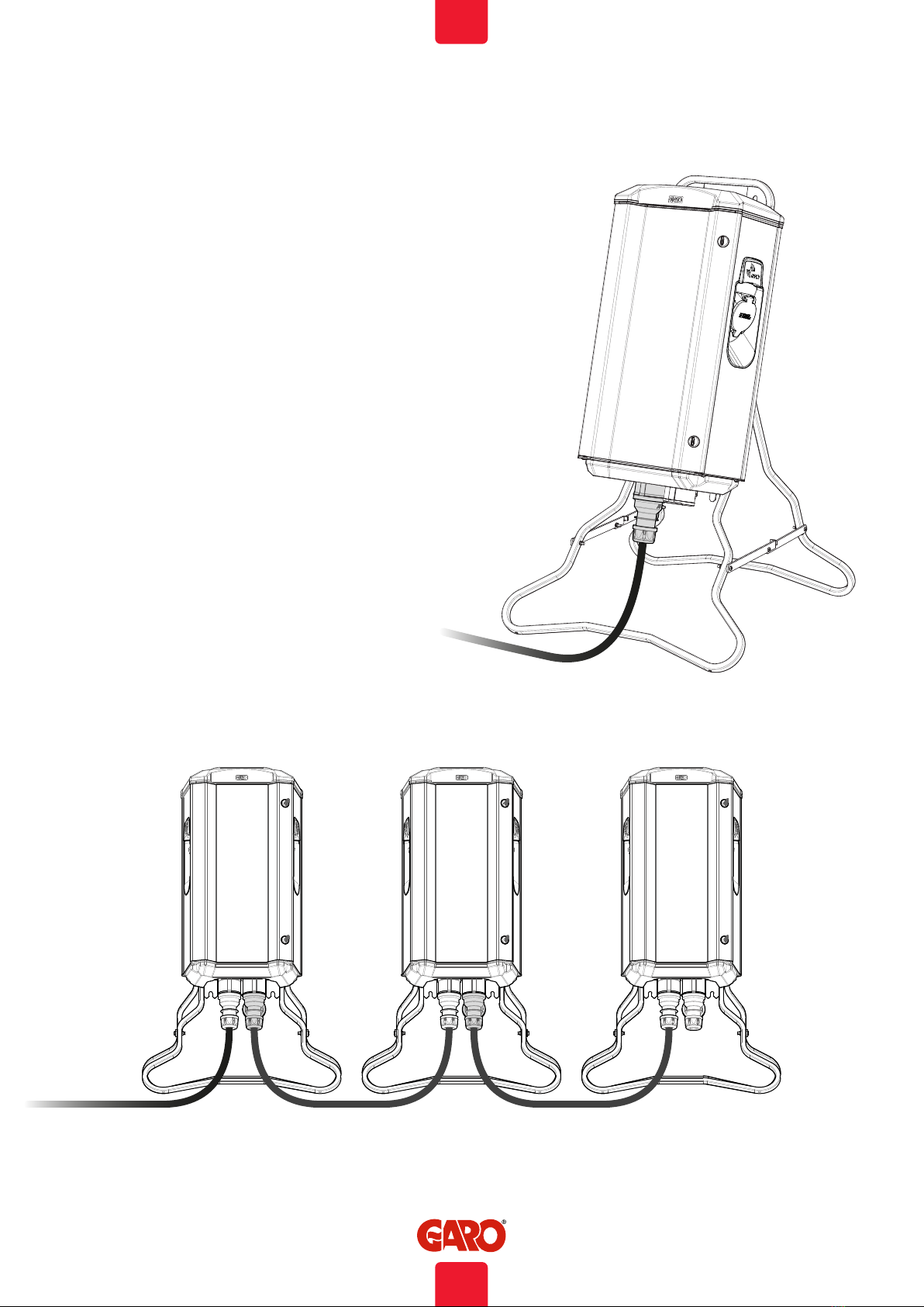
• Double outlets for Mode-3 EV charging.
• Up to 2x7,4kW simultaneous charging from one EVSE
depending on model.
• MCB and RCCB with DC-fault monitoring for each outlet.
• Internal static DLM (Dynamic Load Management).
• Suitable for installation on ground or wall.
• LED status indication.
Some models also have:
• Energy meters for each side
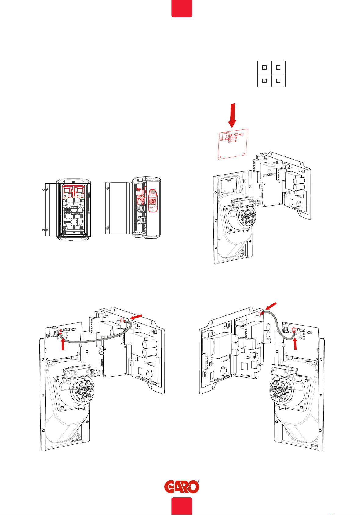
• Communication module for Wifi/LAN functions
• RFID readers
General functions:
• Install and administrate RFID readers
• Connect mobile/tablet/PC to webinterface
• Remote charging activation from a relay/timer etc.
• Update firmware via webinterface
Some functions require specific installed hardware ie
communication module.
For full user manual: www.garoemobility.com/support
Dielectric Voltage Withstand Test is not allowed on GTC
Nova
This equipment should not be used by anyone (including
children) with reduced physical, sensory or mental
capacity, or anyone lacking in experience or knowledge,
unless they are provided with supervision or prior
instruction in how to use the equipment by the person
responsible for their safety.
The GTC Nova range of charging stations is designed
exclusively for charging electric vehicles.
The GTC Nova must be grounded according to local
country installation requirements.
Do not install or use the GTC Nova near flammable,
explosive, harsh, or combustible materials, chemicals, or
vapors.
Turn off the electrical power at the circuit breaker before
installing, configuring or cleaning of the GTC Nova.
Use the GTC Nova only within the specified parameters.
Never spray water or any other liquid directly at the GTC
Nova. Never spray any liquid onto the charge handle or
submerge the charge handle in liquid.
Do not use this equipment if it appears to be damaged or
if the charging cable appears to be damaged.
Do not modify the equipment installation or any part of the
product.
Do not touch the terminals with fingers or any other
objects.
Do not insert foreign objects into any part of the GTB
Nova.
About this manual
This document contains general descriptions which are verified to
be accurate at the time of printing. However, because continuous
improvement is a goal at GARO, we reserve the right to make
product and software modifications at any time. This range
is subject to continual product development. Errors, typo and
omissions excepted.
3
EN
INFORMATION

Cautions
All installation must be carried out by an authorized
installer and comply with local installation regulations.
If any questions, please contact your local electrical
authority.
Ensure that the charging cable is positioned so it will not
be stepped on, driven over, tripped on, or subjected to
damage or stress.
Unroll the charging cable to prevent it from overheating.
Do not use cleaning solvents to clean any of the GTC
Nova’s components. The outside of the GTC Nova, the
charging cable, and the end of the charging cable should
be periodically wiped with a clean, dry cloth to remove
accumulation of dirt and dust.
Be careful not to damage the circuit boards or
components during installation.
Refer to local standards and regulations not to exceed
charging current limitations.
The front cover must always be locked in order to ensure
compliance with IP Code IP44.
Avoid installing the GTC Nova in direct sunlight to avoid
any heat-problems.
To even out the load, it is important to rotate the phases
when connecting several of GTC Nova to the same
supply. Note that 1-phase charging is common in
electric vehicles and L1 and L2 in the GLB is used for this
purpose.
Ventilation signal from EV is not supported.
Adapters for charging connectors are not allowed to be
used.
Cord extension sets for charging cable is not allowed to
be used.
Electrical vehicles (EV) software and the GTC Nova
firmware are continuously updated.
To make sure that the GTC Nova is working properly,
it is necessary to update the firmware and it requires a
communication card.
Communication cards are available as an accessory.
GTC Nova charging station is designed for safe electric
vehicle charging for temporary installations.
When installing NOVA charging station, the supply cable
should be preceded by an RCCB type A.
When used in public environments, such as events of
various kinds, incoming and outgoing CEE shall be locked
with appropriate protection. Appropriate protection is
available in GARO’s range.
Do not use private power generators as a power source
for charging. Variations in the electrical voltage can
damage the vehicles battery and/or the GTC Nova itself.
Incorrect installation and testing of the GTC Nova could
potentially damage either the vehicle’s battery and/or the
GTC Nova itself.
Do not operate the GTC Nova in temperatures outside its
operating range – see technical specifications.
Notes
4
EN
INFORMATION

INSTALLATION OF STANDALONE GTC NOVA
The installation must be performed by a professional electrician.
The installed mains cable need to handle up to 32A during long
term period.
Calculate the required cable length and select the appropriate
cable-area to minimize the risk of voltage-drop.
Follow local country regulations.
Left hand side PCB (CC1) controls the left side outlet/cable and
the right hand side PCB (CC2) controls the right hand side outlet/
cable.
1. Select the appropriate group fuse and cable size for the
electrical installation. GTC Nova have a CEE inlet where the
mains cable.
NOTE! Due to high currents for a long time in the cable, there is a
high risk of voltage drop if the cable is under-dimensioned which
can damage the electronics in an EV.
2. Mount the GTC Nova according to picture 1.
(picture 1)
5
EN
INSTALLATION OF STANDALONE GTC NOVA

3. You can by setting Dip switch SW2 on both CC1 and CC2
(picture 2 and 3) reduce the charging current for left or right hand
side if needed. Normally, this is normally not necessary. Available
range is 6-32A (table 1 and picture 4).
It is allowed to set different values on left and right hand side.
4. Install the electrical power supply cable in the CEE inlet, see
picture 3.
(table1)
SW2 MAX Ampere
SW2
ON OFF
3 3=OFF
6A2 2=OFF
1 1=ON
3 3=OFF
10A2 2=ON
1 1=OFF
3 3=OFF
13A2 2=ON
1 1=ON
3 3=ON
16A2 2=OFF
1 1=OFF
3 3=ON
20A2 2=OFF
1 1=ON
3 3=ON
25A2 2=ON
1 1=OFF
3 3=OFF
29A2 2=OFF
1 1=OFF
3 3=ON
32A2 2=ON
1 1=ON
(picture 4)
(picture 3)
SW2
CC1 CC2
SW2
(picture 2)
GTC 7,4 kW = 32 A
6
EN
INSTALLATION OF STANDALONE GTC NOVA

5. Turn on the electrical power to the GTC Nova.
6. For GTCDCW… models: Connect a mobile device (PC/
Tablet/Mobile) to the GTC Nova Wifi network. You find SSID and
password on the label inside the front door. Type in 172.24.1.1
in your web browser and check that the GTC web interface is
visible. This action confirms that the GTB Twinbox communication
module is working properly.
7. Test the GTC Nova both sides with a test instrument or test to
charge an electric vehicle to ensure that the GTC Nova is working
properly.
(picture 5)
(picture 6)
7
EN
INSTALLATION OF STANDALONE GTC NOVA

(picture 7)
(picture 8) (picture 9)
1. Turn off the electrical power to the GTC Nova
2. Assembly the RFID readers according picture 7-9.
Note: Both DIP switches should set to ON on both RFID readers,
see picture 10.
A wifi module needs to be installed to the Master GTC Nova.
RFID reader installation
(picture 10)
DIP switch ON OFF
2
1
8
EN
INSTALLATION OF STANDALONE GTC NOVA

RFID settings for stand alone GTC Nova
SW1
(picture 11)
Set SW1 (Dip5) CC2 to ON that makes the unit as “Master”,
see picture 11.
For RFID setting, see section web interface.
9
EN
INSTALLATION OF STANDALONE GTC NOVA

Dimensional sketch
660
206
377
10
EN
INSTALLATION OF STANDALONE GTC NOVA

Normal use / Charging
Connect the charging cable to the EV. Charging will start
immediately if the EV is ready for charging. See your EV charging
manual.
When finishing charging, follow the car’s instructions.
After charging: Release first the charging cable from your EV and
place the charging cable at designated place.
Note!
It is the EV that determines how much electrical current (A) the
GTC should provide. GTC Nova can provide the maximum rated
power according to the rating label. When both sides are in use,
the GTC Nova will balance the load equally between both sides.
In cases where the required power exceeds the available power
to the Nova, the left hand side is prioritized.
The GTC Nova is equipped with outlets, and it is important to use
correct charging cable.
For example, if you want to use 32A from the Nova, you must use
a 32A charging cable.
Note that there are both 1-phase and 3-phase charging cables
in the market. Use the correct cable to your EV. To find the correct
type of cable needed to your EV, please see the EV manual.
USER MANUAL
11
EN
USER MANUAL

Resetting/Conditioning of RCCB
In the event of overload/earth fault, the built in RCCB/RCBO
can trip, see picture 12. These components also need to be
conditioned by pressing the test button every 6 month.
Procedure to reset/condition:
1. Disconnect the EV from the Nova
2. Open the front door.
3. Reset the RCCB (B). Conditioning means that first press the test
button (A) and then reset the RCCB (B).
4. Close the front door.
Front door should be closed and locked to achieve IP44 class.
A
B
(picture 12)
Left/vänster
Right/höger
12
EN
USER MANUAL

-XD2
-KF1
-XD1
-RFID1 -RFID2
1EPX-1NX-
-QA1 -QA2
-CC1 -CC2
-FB1
-FB2-FC2
1P-1CF-
-P2
-X1
L3 N PEL1 L2
16/32A
16/32A
Electrical diagram
P1 =Energymeter Left Outlet
P2 =Energymeter Right Outlet
FB1 =RCCB Left Outlet
FB2 =RCCB Right Outlet
FC1 =Fuse Left Outlet
FC2 =Fuse Right Outlet
QA1 =Contactor Left Outlet
QA2 =Contactor Right Outlet
XN1 =N Neutral terminal
XPE1 =PE Terminal Protection Earth
CC1 =Charge Controller Left
CC2 =Charge Controller Right
RFID1 =Left Receiver
RFID2 =Right Recevier
KF1 =Led light Topcard
X1 =Incoming terminal
XD1 =Left charging connector
XD2 =Right charging connector
13
EN
USER MANUAL

I
16/32A
-FC2
6
5
8
7
2
1
4
3
7
1 2 3
4 5 6
8 9 10 11 12
N N
-P2
7
1 2 3
4 5 6
8 9 10 11 12
N N
-P1
I
16/32A
-FC1
6
5
8
7
2
1
4
3
N 5
-FB2
40A
N 62 4
1 3
mA
30
N 5
-FB1
40A
N 62 4
1 3
mA
30
L3
L2
L1
N
PE
-X1
2
1
6
4
5
3
8
7
A1
A2
-QA1
2
1
6
4
5
3
8
7
A1
A2
-QA2
CT2
CT1
CP
PP
L1
L2
L3
PE
N
-XD2
CP
PP
L1
L2
L3
PE
N
-XD1
CT1
CT2
-XPE1-XN1
PP 2
CP 2
Red
White
PP 1
CP 1
Red
White
LINE (L)
FC2
FC1
XN1
XPE1
A-
B+ -P1 + lastbalansering
QA1
QA2
A-
LASTBALANSERING
B+
A-
B+ DATALINK
A-
DATALINK
B+
A-
B+
-P2
14
EN
USER MANUAL

Fuse/RccB FB
Contactor FB
Contactor control
Line (L)
Neutral (N)
Protective earth (PE)
A-
B+
Remote control
A-
B+
ON
SW2
12345 6
ON
SW1
E-Meter
Datalink
Fuse
1. blue/brown
2. blue/red
3. blue/yellow
4. blue/green
5. white
6. red
Fuse/RccB FB
Contactor FB
Contactor control
Line (L)
Neutral (N)
Protective earth (PE)
A-
B+
A-
B+
ON
SW2
1234 5 6
ON
E-Meter
Datalink
Fuse
1. blue/brown
2. blue/red
3. blue/yellow
4. blue/green
5. white
6. red
Connector for
WLAN-Card
CP 2
PP 2
CT2
CP 1
PP 1
CT1
FC1
FC2
XN1
XPE1
A-
B+
-P1 + lastbalansering
A-
B+
DATALINK
QA1
QA2
M
GR/BL
YE/BL
RE/BL
BR/BL
LINE (L)
A-
B+
-P2
communication cable
communication cable
-KF1
Connector for
Led light Topcard
Connector for
the RFID reader
Connector for
the RFID reader
M
GR/BL
YE/BL
RE/BL
BR/BL
USER MANUAL
15
EN

Connecting to GTC Nova Wifi access point (AP)
(Only for GTC with wifi module installed)
1. Make sure that the GTC Nova is turned on.
2. Check the Serial no./SSID and password on the label which
can be found inside the front door. Make a note of the serial
number/SSID and password in the box below for future
reference.
3. Identify the wallbox’s SSID name in the wireless network
display on your phone, tablet or computer see (picture
23) Connect to the Nova wireless network and enter the
password.
4. Launch the browser on your device. The device will display the
Nova website automatically or type in 172.24.1.1
To connect the GTC Nova to a local wireless network, see the
section entitled “Connect GTC Nova
to a local network via Wi-Fi”.
(picture 13)
16
EN
USER MANUAL

Web interface
You can see information and do settings in the web interface.
Below are some examples. (Due to continuous development, there
might be more features in the web-interface than listed below and
the pictures can vary).
Warning! GARO recommend that settings should be done by a
person that have enough knowledge and good experience of a
GTC Nova. If wrong setting is done for example DLM functions,
it can result in overload for the installation and it can cause
operational failure.
Note:
When the GTC Nova is connected to your local network, you
should use the url: chargebox.garo.se in your web browser. Your
mobile device needs to be connected to same network as the
GTC Nova.
• Settings for scheduled reduced charge current (not active
when external energy meter installed)
• Activating and deactivate RFID function
• Activating and deleting RFID tags
• Connecting to local Wifi network and LAN settings
• G-Cloud information and settings (only for G-Cloud systems)
• Energy consumption (only master GTC, require installed
energy meter)
• Updating of the GTC Nova firmware
• Schedule functions
• Enable/disable GTC Nova
Main menu
Doubleclick the GARO symbol to show enhanced information
17
EN
USER MANUAL

Example of information for left and right hand side
18
EN
USER MANUAL

Energy information
Information for consumed energy for each side of the GTC
19
EN
USER MANUAL

RFID settings in the web interface
After activate the RFID check, you can add and remove RFID tags
manually or read in RFID tags via the RFID reader (Read tag from
wallbox).
Note: when multiple GTC Novaes are connected in a grid, you
can activate RFID tags individually for each Nova.
You can also add a name or comment for each tag.
Read tag from wallbox: Hold the tag against the RFID reader and
the tags ID is shown in the interface. Press save.
When RFID check is activated, you need to hold an active RFID
tag against the RFID reader to activate the charging process. A
ticking sound will indicate that the GTC is waiting for the RFID tag.
The ticking continues in 30sek. After that, you need to reconnect
the charging cable to the vehicle again and restart the process.
If the RFID tag is accepted, the charging process will begin. Red
light from GTC indicates that the tag is not accepted.
To erase a RFID tag, click the “-“ at the side of the registered tag.
Schedule
Settings menu for scheduled activation of GTC Nova.
USER MANUAL
20
EN
Other manuals for Nova GTC
1
Table of contents
Popular Industrial Electrical manuals by other brands

Murata
Murata GRM0335C1H5R9BA01 Series Reference sheet

Murata
Murata GRM0225C1E2R5CA03 Series Reference sheet

Moeller
Moeller DILM185-S installation instructions

Rockwell Automation
Rockwell Automation Allen-Bradley Guardmaster GuardLink... installation instructions

ABB
ABB EBN861 Operating instruction

Murata
Murata GRM1885C1H5R9CA01 Series Reference sheet