BDStar Harxon eRadio User manual


Version/Warranty/Repair/Copyright
Version Information
Version Number: V1.3
Version Date: Aug 23, 2019
Warranty Period
eRadio: 1 year
Instruction of Returning to the Factory
If something is wrong with the product, it should be returned to the factory,
please contact us.
Copyright Information
The operation guide of this product and all involving software are protected by
Harxon Corporation (hereinafter referred to as Harxon). All rights are reserved.
All rights of this manual, including copyright, are exclusively owned by Harxon.
Unless permitted by the copyright owner, this manual is prohibited from being
copied by the means of printing, duplicating or recording, etc.
Disclaimer
During the compilation, this manual strives for the accuracy and completeness
of contents, but Harxon assumes no responsibility for any possible error or
omission. Due to continuous development of technology, Harxon is entitled to
change the technical specifications or functions of its products without
informing users in written form.

Contents
Version/Warranty/Repair/Copyright.....................................2
Warranty Period .................................................2
Instruction of Returning to the Factory ..............................2
Copyright Information ............................................2
Disclaimer ......................................................2
Contents............................................................3
Diagram Index.......................................................5
Table Index .........................................................6
Notice..............................................................7
Meanings of Signs in This Manual..................................7
Information of Certification Passed by This Product ..................7
English Abbreviation A-Z in This Manual ............................7
User Service ........................................................8
Common Problem Analysis .......................................8
Record Information...............................................8
Contact Us......................................................8
1 Introduction .......................................................9
1.1 Product Features............................................10
1.2 Convention .................................................10
2 Interface and Component ..........................................11
2.1 Interface of Serial Port Data Cable.............................11
2.2 Radio Frequency Interface....................................11
2.3 Instruction of Indicator Lights..................................11
2.4 Bluetooth Module (Optional) ..................................12
2.5 Network Module (Optional) ...................................12
3 Functions and Operation Instruction .................................13
3.1 Startup & Shutdown Button ...................................13
3.2 Left and Right Buttons .......................................13
3.3 Up and Down Buttons........................................13
3.4 Data Transmitting-receiving Indicator Light......................13
3.5 GPRS and Bluetooth Operating Condition (Optional) .............13
3.6 Instruction of Radio Startup and Power Indicator Light Conditions..14
3.7 Device Menu................................................14
3.7.1 Device Information.....................................14
3.7.2 Transmitting/Receiving Channel and Frequency ...........15
3.7.3 Data Protocol .........................................15
3.7.4 RF Baud Rate.........................................16
3.7.5 Transmitting/Receiving Mode............................16
3.7.6 Transmitting Power ....................................16
3.7.7 Serial Port Baud Rate ..................................17
3.7.8 Serial Port Baud Rate Self-adaption......................17
3.7.9 OLED Sleep Mode.....................................18

3.7.10 Interference Detection.................................18
3.7.11 Language............................................19
3.8 Use of Radio Configuration Software...........................19
3.8.1 Configuration Environment..............................19
3.8.2 Configuration Tool Installation ...........................20
3.8.3 Radio Parameter Query ................................21
3.8.4 Radio Parameter Configuration ..........................23
3.9 Bluetooth APP ..............................................24
3.9.1 Configuration Tool Installation ...........................24
3.9.2 Configuration Tool‟s paring and connection ...............25
3.9.3 Radio Parameter Configuration and Query ................27
3.10 Firmware Upgrade..........................................28
Appendix A Technical Indexes........................................32
A.1 Specifications and Parameters of Data Transmission Radio.......32
A.2 Bluetooth Parameters........................................33
A.3 Network Parameters.........................................33
A.4 eRadio Suite Parts ..........................................34
A.4.1 Radio Configuration Cable (HJ394) (Optional).............34
A.4.2 Power Cable (HJ379) ..................................35
Appendix B Command...............................................37
Appendix C eRadio SIM Setup .......................................42


Table Index
Table 1 Meanings of Signs in This Manual...........................................7
Table 2 Information of Certification Passed by This Product
(supplemented to be complete).............................................................7
Table 3 eRadio Data Interface Definition ............................................11
Table 4 Specifications and Parameters of Radio...............................32
Table 5 Specifications and Parameters of Bluetooth Module...........33
Table 6 Specifications and Parameters of Network Module②..........33
Table 7 List of Radio Configuration Cable HJ394 Parts....................34
Table 8 Definition of HJ394 Data Cable B Port................................35
Table 9 List of Power Cable HJ379 Parts............................................36
Table 10 eRadio Background Configuration Mode Command Format
................................................................................................................37
Table 11 List of eRadio Background Configuration Mode Commands
................................................................................................................38

Notice
Meanings of Signs in This Manual
Table 1 Meanings of Signs in This Manual
Sign
Meaning
Remarks
①
Indicate there are notes in the
page for this index/matter
When there are multiple notes in
one page, the number in the sign
will increase.
Some matters requiring users‟
attention
Information of Certification Passed by This Product
Table 2 Information of Certification Passed by This Product
Standard
Remarks
FCC
Rules and Regulations : FCC Part 15B
CE
RED Article3.2 Radio
RED Article3.1(b) EMC
RED Article3.1(a) Safety
RED Article3.1(a) Health
RoHS
RoHS Directive 2011/65/EU and its amendment directives –XRF screening test and
Wet Chemical Testing (Lead, Cadmium, Mercury, Hexavalent Chromium, PBBs &
PBDEs content)
REACH
One hundred and seventy three (173) substances in the Candidate List of
Substances of Very
High Concern (SVHC) for authorization published by European Chemicals Agency
(ECHA) on
and before January 12, 2017 regarding Regulation (EC) No 1907/2006 concerning
the REACH
IP67
English Abbreviation A-Z in This Manual
APN Access Point Name
ASCII American Standard Code for Information Interchange
BT Bluetooth
GPS Global Positioning System
IP Internet Protocol

User Service
Common Problem Analysis
If you encounter some technical problems, refer to Section eRadio FAQ in this
manual. This part describes the phenomena, causes and solutions of some
common problems.
Record Information
If the technical problems you encounter are not recorded in the manual, make
a record of the operating environment, use procedure, problem phenomenon
before and after device abnormality, as well as information such as product
model, product hardware version and firmware version.
Product model, product hardware version and firmware version can be queried
through eRadio configuration tools.
Contact Us
Please contact us for more help.
Service Hotline: +86-755-26989948 (8:30-12:00 13:30-18:00)
Sale Hotline: +86-755-86578389 (8:30-12:00 13:30-18:00)
Company Fax: +86-755-26989994

1 Introduction
As a type of external transmitting-receiving data radio, eRadio supports many
options of transmitting power, with waterproofing grade up to IP67 and sturdy
and durable structure, applicable for outdoor use under all weather conditions.
eRadio is equipped with 3 bi-color indicator lights (Wireless
transmitting-receiving indicator light: green while receiving, red while
transmitting; Power indicator light: green for normal supply, red for
under-voltage; GPRS and Bluetooth indicator light: green indicator light links
to GPRS, red indicator light links to Bluetooth), one OLED display and five
buttons, convenient for human-computer interaction.
Figure 1 eRadio

1.1 Product Features
Main features of eRadio:
Full-band support, with the frequency point range of 410MHz -470MHz
Many options of transmitting power
Self-adaptive function of serial port baud rate
OLED display
5 user buttons
One-way RS232 interface
Bluetooth module
4G module
3 bi-color status indicator lights
IP67 protection
Note:
Optional component.
1.2 Convention
The following conventions are used in this manual:
The characters following 0x are hexadecimal digits
The characters used by transmitted commands are case insensitive
2 Interface and Component
2.1 Interface of Serial Port Data Cable
The interface of serial port data cable uses the asynchronous serial
communication RS232 standard.
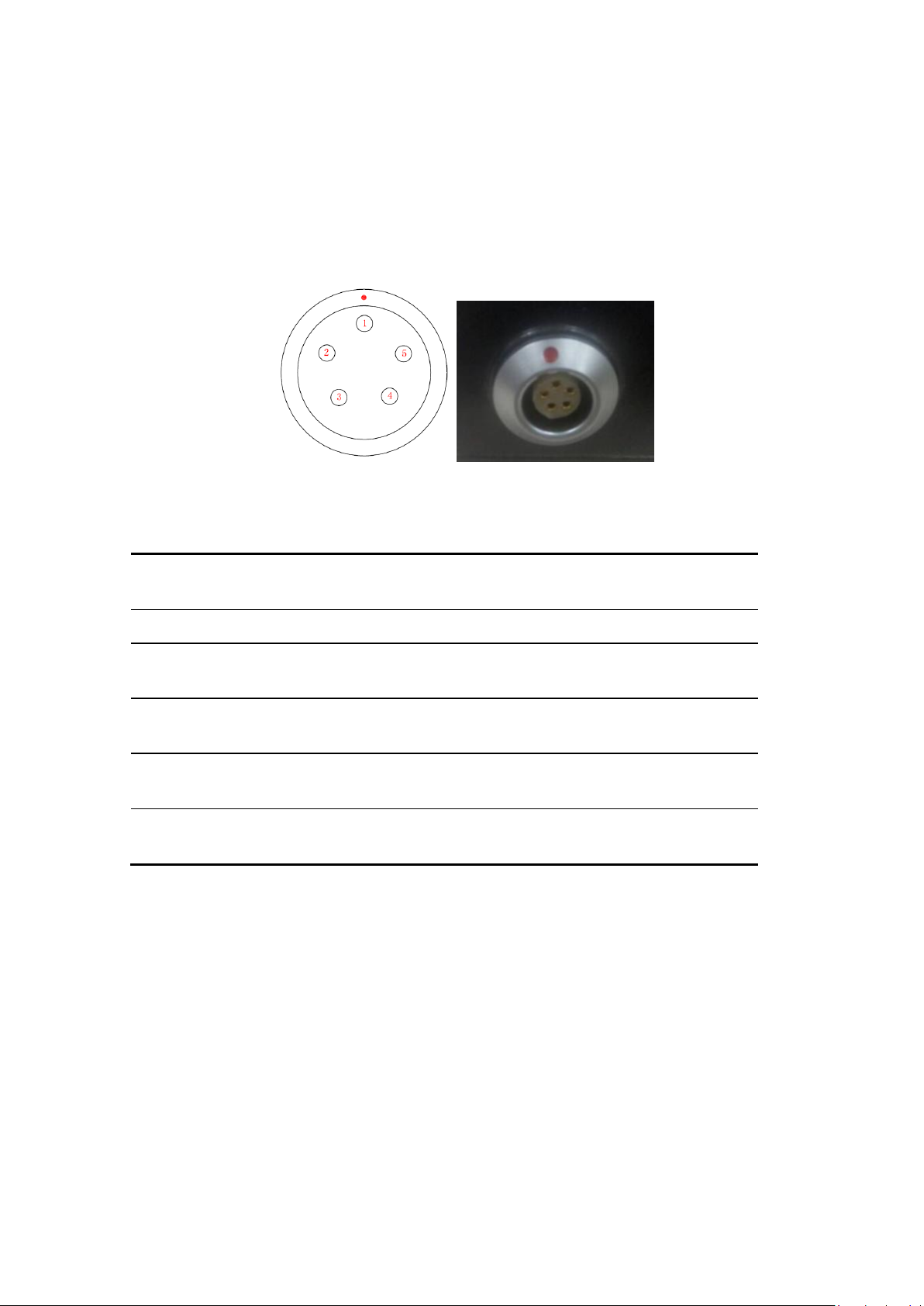
Figure 2 Diagram of eRadio Data Interface
Table 33 eRadio Data Interface Definition
Pin
Nam
e
Description
Remarks
1
VCC
Power output
DC9-16V
2
GND
1
Power Ground
3
RXD
Serial port data
receiving
RS232 Level
4
GND
2
Signal Ground
5
TXD
Serial port data
transmitting
RS232 Level
2.2 Radio Frequency Interface
The eRadio radio frequency interface uses 50 OHM TNC negative connector.
2.3 Instruction of Indicator Lights
GPRS/BT is GPRS and Bluetooth red and green indicator light, red
indicator light represents GPRS module and green one represents
Bluetooth module;
RX/TX is data transmitting-receiving red and green indicator light, green
indicator light represents data receiving, red indicator light represents data
transmitting;

PWR/ALM is bi-color indicator light for normal power supply and
under-voltage, green indicator light represents normal power supply, red
indicator light represents abnormal voltage;
2.4 Bluetooth Module (Optional)
If the current radio supports Bluetooth, users can configure and query the radio
parameters by the means of Bluetooth, Bluetooth V4.0 is supported;
2.5 Network Module (Optional)
If the current radio supports network data transmission, users can transmit
their data via network, now radio can be used as CORS station, without the
need of RTK device, thus saving cost and simplifying outdoor operation. In
addition, network module supports 4G.

3 Functions and Operation
Instruction
3.1 Startup & Shutdown Button
The startup & shutdown button (power button) can be used to control radio
power-on and power-off, with specific functions as follows:
Short press the startup button for about 1 second to power on, the green
power indicator light illuminates in the case of successful power-on (under
the condition of normal power supply).
Under the condition of power-on, long press the startup button for 3
seconds to power off, the power indicator light goes out and the display is
closed.
The function of menu parameter confirmation
3.2 Left and Right Buttons
You can switch over various function menus through the left and right buttons.
3.3 Up and Down Buttons
In the current menu, you can select the corresponding menu item through the
up and down buttons.
3.4 Data Transmitting-receiving Indicator Light
While transmitting data, the red RX/TX indicator light illuminates; while
receiving data, the green RX/TX indicator light illuminates.
3.5 GPRS and Bluetooth Operating Condition
(Optional)
Include various operating conditions of the GPRS module and Bluetooth
module shown as below, if any module is abnormal, this condition can be
convenient for users to locating the problem:
If GPRS enters the condition of network data transmission successfully,
the red indicator light flickers once in three second;
If GPRS is detecting SIM card, the red indicator light flickers twice in three
second;
If GPRS is trying to access network, the red indicator light flickers four
times in three second;

If GPRS is re-connecting to the Corse station or server successfully, the
red indicator light flickers five times in three second;
Bluetooth led(green)is reserved.
3.6 Instruction of Radio Startup and Power Indicator
Light Conditions
Normal radio startup & shutdown has memory function, abnormal radio startup
& shutdown has memoryless function, with specific functions as follows:
In the case of abnormal shutdown for the last time, power on again after
outage, the radio powers on automatically;
In the case of normal shutdown for the last time, only by short pressing for
about 1 second can the radio power on after powering;
If the voltage is lower than the under-voltage threshold value (11.0V by
default, depending on the user‟s actual setting value), the red power
indicator light flickers twice in one second;
If the voltage is lower than the forbidden threshold value (10.2V by
default, depending on the user‟s actual setting value), the red power
indicator light flickers once in one second;
If the voltage is higher than the under-voltage threshold value (11.0V by
default, depending on the user‟s actual setting value), the green power
indicator light illuminates constantly;
When the voltage alarm appears, if it is under-voltage alarm, you need add
0.3V based on the under-voltage threshold value to resume to the normal
voltage operating condition (the green power indicator light illuminates
constantly);
Notes:
Abnormal shutdown means you do not power off by long pressing the
power button, for example, directly disconnecting power;
Normal shutdown refers to power-off by long pressing the power button;
3.7 Device Menu
It is categorized into two types of menus altogether: Basic radio parameter
menu and other features/functions menu.
3.7.1 Device Information
In the information column, the current channel number, current transmitting
frequency, current receiving frequency, current protocol, current transmitting

power, battery condition, device model, firmware version, hardware version
and serial number are displayed.
3.7.2 Transmitting/Receiving Channel and Frequency
In this menu column, you can set up the current transmitting/receiving
frequency, select required communication frequency through up and down
buttons, and press the OK key to select this frequency as the current
communication frequency point, the character of“*”will appear after selection.
3.7.3 Data Protocol
In this menu column, you can set up the current communication protocols such
as TRANSEOT, TRIMTALK and TRIMMK3. Select required communication
protocol through up and down buttons, and press the OK key to select this
protocol as the current communication protocol, the character of“*”will appear
after selection.
Note: After changing the protocol, you need reselect the RF baud rate
supported by the current protocol in the menu of “wireless link rate”;
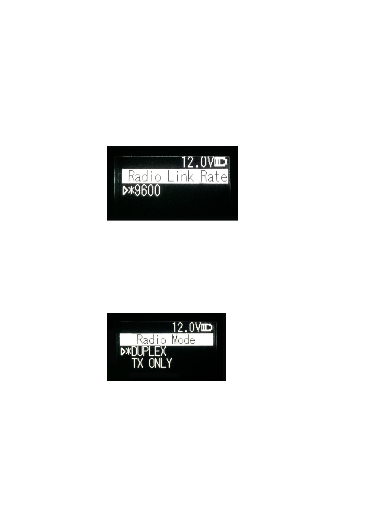
3.7.4 RF Baud Rate
In this menu column, you can set up the current communication RF baud rate.
Different protocols support different types of RF baud rates. For example,
TRANSEOT supports 4800,9600, while TRIMMK3 supports 19200. Select
required RF baud rate through up and down buttons, and press the OK key to
select this RF baud rate as the current communication RF baud rate, the
character of“*”will appear after selection.
3.7.5 Transmitting/Receiving Mode
In this menu column, you can set up the current radio transmitting/receiving
mode. Now, four types of transmitting/receiving modes are supported:
transmitting-receiving, single transmitting, single receiving and relaying mode.
Select required transmitting/receiving mode through up and down buttons, and
press the OK key to select this transmitting/receiving mode as the current
communication transmitting/receiving mode, the character of“*”will appear
after selection.
3.7.6 Transmitting Power
In this menu column, you can set up the current wireless transmitting power
level. Now, three levels of power, high, medium and low, are supported, these
three levels of power values can be customized according to the demands of
users. Select required transmitting power through up and down buttons, and
press the OK key to select this transmitting power as the current
communication transmitting power, the character of“*”will appear after
selection.

3.7.7 Serial Port Baud Rate
In this menu column, you can set up the current serial port communication
baud rate. Now, there are the following baud rates: 9600, 19200, 38400,
57600, 115200. Select required serial port communication baud rate through
up and down buttons, and press the OK key to select this serial port
communication baud rate as the serial port communication baud rate of the
current communication, the character of“*”will appear after selection.
3.7.8 Serial Port Baud Rate Self-adaption
In this menu column, there are two options: self-adaptive master switch and
triggering enabling. The former has memory function, if turning on the switch,
ON is displayed on the menu; if off, then OFF is displayed; self-adaptive
triggering enabling does not have memory function, the system remains in the
startup condition after power-on; only if the self-adaptive master switch has
been turned on can the adaptive function of serial port baud rate work
normally.
If the serial port baud rate is successfully self-adaptive, a message box pops
up indicating successful self-adaptive matching, meanwhile, self-adaptive
triggering enabling stops automatically. If the serial port baud rate is not
successfully self-adaptive, this function is always operating.
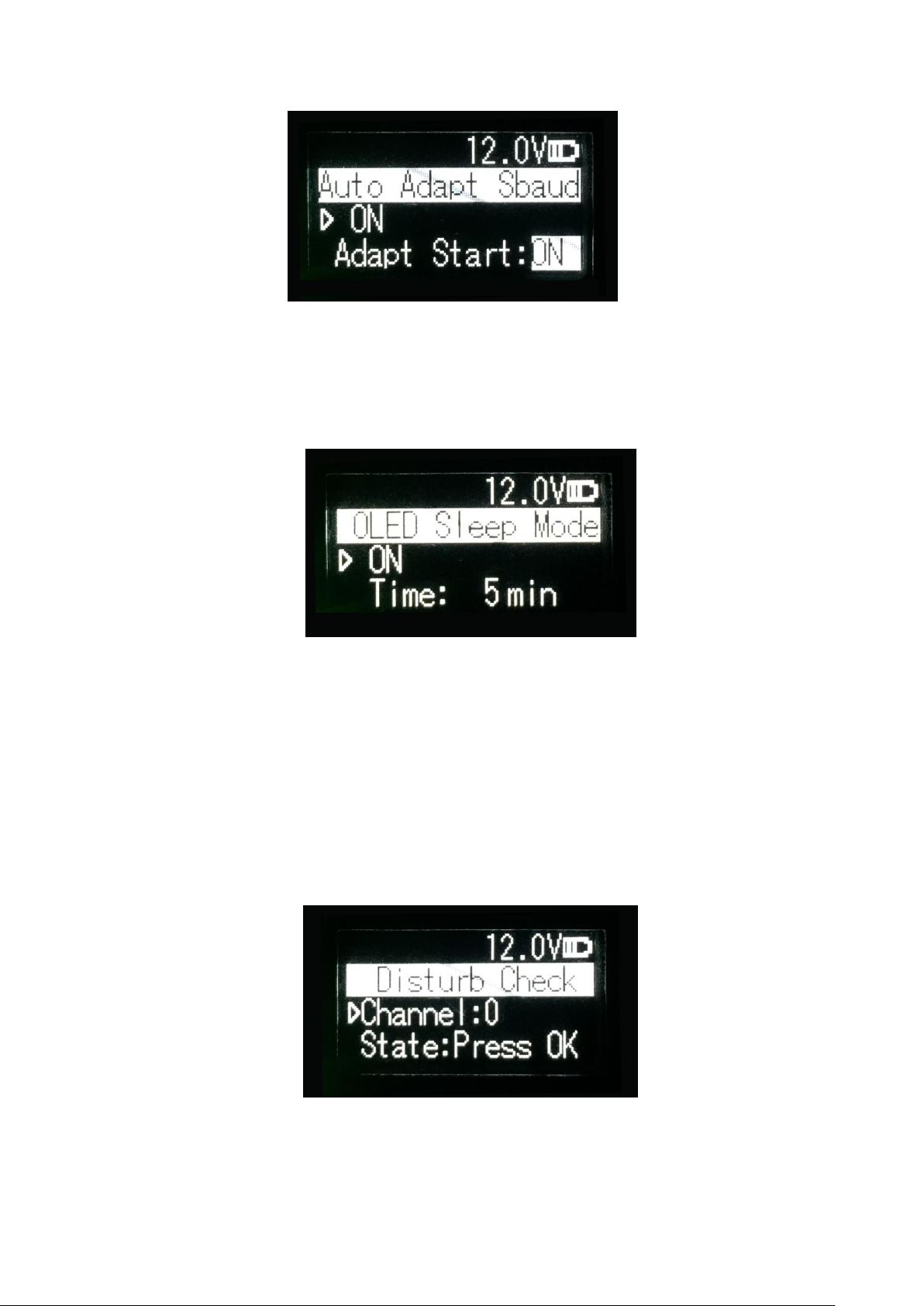
3.7.9 OLED Sleep Mode
Set up whether the OLED display enters sleep, only if the “Function” switch is
in the “On” mode can the OLED display enter the sleep mode, sleep time has
the following levels: 1min, 5min, 10min, 15min, 20min, 25min, 30min.
Note:
After the OLED display enters sleep, you can awaken it through button and
pop-up window message.
3.7.10 Interference Detection
Detect whether there is any interference in the current channel. You can
modify the detection channel number manually and press the OK key for
detection, there are three levels of detection result: superior, moderate, poor.

3.7.11 Language
Set up the display language of device fonts, Chinese and English are
supported for this terminal.
3.8 Use of Radio Configuration Software
Multiple forms of configuring radio parameters are supported. Users can
change and query the current radio parameters by the means of background
mode, user interface mode and PC configuration tool. The use methods of the
PC configuration tool are introduced as below.
The procedures of radio parameters include:
Communication link establishment
Configuration tool installation
Radio parameter query
Radio parameter configuration
3.8.1 Configuration Environment
Firstly, build up the radio parameter configuration environment, devices
needed include: Power supply (12V), power cable (integration of power cable
and data cable), radio, PC. And then, assemble related components according
to Figure 3
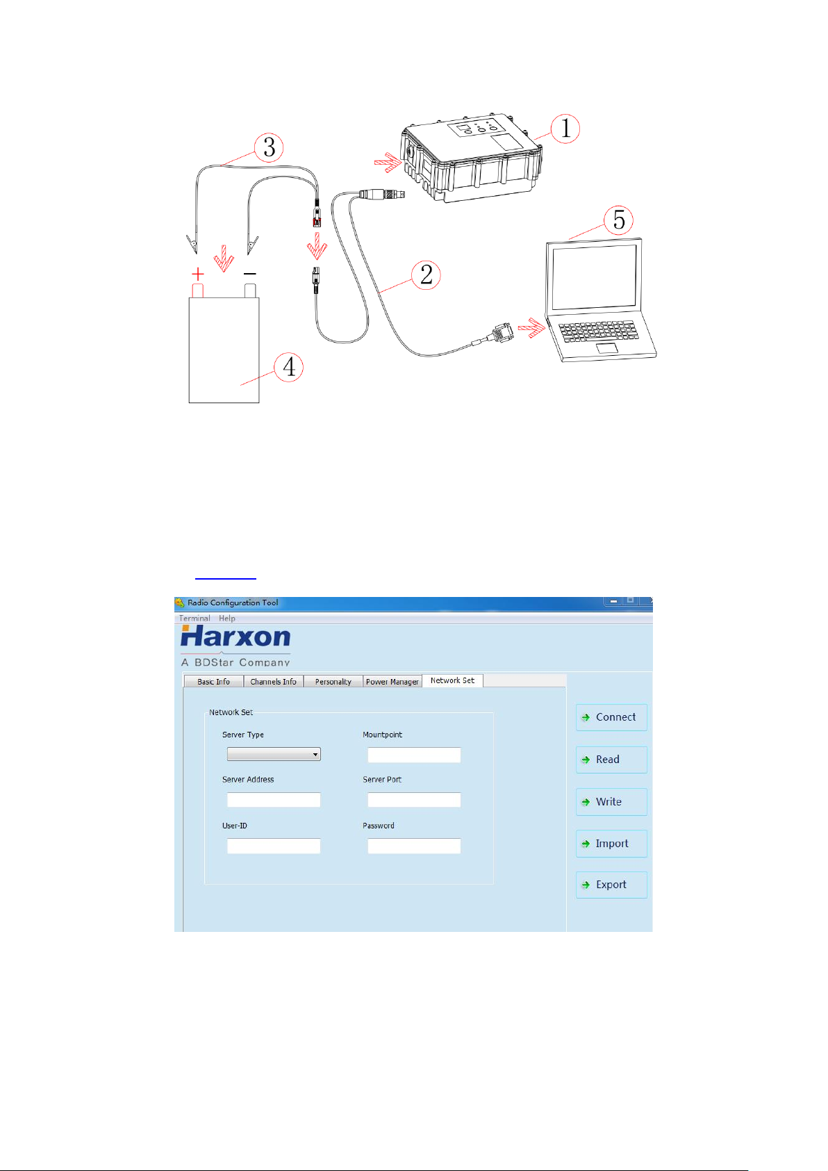
Figure 3 Installation Instruction
3.8.2 Configuration Tool Installation
Open the configuration tool installation file and click “Next” until installation is
completed. In the end, one shortcut appears on the desktop. During the radio
configuration later, you can directly open this shortcut to operate the radio, as
shown in Figure 4.
Figure 4 Radio Query/Configuration Software Interface
Note:
During the use of the configuration tool for radio parameter configuration and query, radio is
not allowed to enter the background parameter configuration mode.
Table of contents


