E10
LAMP TYPE:
5. Using a 3/32” hex wrench, loosen set screws on either side of the Angling
Bracket. Adjust to desired angle and retighten screws (Figure 1).
6. Join xture leads to wires coming from transfomer using silicone-lled wire nuts
to ensure proper connection.
7. Fill bottom 4” of Tubing with pea gravel. Fixture can be set in concrete, but
concrete must only be poured AROUND xture — the bottom must remain open
to the earth for drainage.
8. Replace xture assembly onto Brass Tubing. Rotate as needed to aim lamp,
then tighten set screws loosened in Step 2.
9. Back ll hole around the outside of Tubing.
WARNING — Risk of Electric Shock. Verify that power is OFF before installing this
xture. This xture must be installed in accordance with the National Electric Code and
local codes. Failure to do so
may result in serious personal injury or death. Wiring must
be done by a licensed electri
cian.
INSTRUCTIONS PERTAINING TO A RISK OF FIRE OR INJURY TO PERSONS
IMPORTANT SAFETY INSTRUCTIONS SAVE THESE INSTRUCTIONS
Lighted lamp is HOT!
WARNING – To reduce the risk of FIRE OR INJURY TO PERSONS:
• Turn off/unplug and allow to cool before replacing lamp.
• Lamp gets HOT quickly! Contact only switch/plug when turning on.
• Do not touch hot lens or faceplate.
• Keep lamp away from materials that may burn.
• Do not touch the lamp at any time. Use a soft cloth. Oil from skin may damage lamp.
• Do not operate the luminaire fitting with a missing or damaged faceplate or lens.
This is a low-voltage xture for use with maximum 25A, 15V power units only. A remote transformer
is required. Do not overload the transformer by installing or relamping with higher wattage lamps that
together exceed the capacity of the transformer.
The unit low-voltage cable shall: a) be protected by routing in close proximity to the luminaire or tting,
or next to a building structure such as a house or deck; b) not be buried except for a maximum 6 inches
(15.2 cm) in order to connect to the main low-voltage cable; and c) have the length cut o so that it is
connected to a connector within 6 inches (15.2 cm) from a building structure, a luminaire, or tting. Con-
tact Beachside Lighting for low voltage cable and direct burial wire for use as main secondary wiring.
For luminaires equipped with halogen lamps:
MR16 GU5.3 bi-pin base — Maximum 15 Watts LED, 35 Watts halogen
LED module — Maximum 4 Watts (suitable for indoor use)
• FOR USE WITH LANDSCAPE LIGHTING POWER SUPPLY ONLY
• THIS DEVICE IS ACCEPTED AS A COMPONENT OF A LANDSCAPE LIGHTING SYSTEM
WHERE THE SUITABILITY OF THE COMBINATION SHALL BE DETERMINED BY THE LOCAL
INSPECTION AUTHORITIES HAVING JURISDICTION
• DO NOT CONNECT TWO OR MORE POWER SUPPLIES IN PARALLEL
• Unless equipped with LED module, LANDSCAPE LIGHTING SYSTEMS ARE FOR OUTDOOR
USE ONLY
• NOT FOR USE IN DWELLING UNITS
• A luminaire shall not use tungsten halogen lamps unless the luminaire is marked for such lamps
INSTALLATION
1. Dig a hole 8” diameter by 8” deep at the desired location.
2. Verify that power to xture is o. Loosen set screws located on Top Plate inside
the two oval holes with a 5/64” hex wrench (Figure 2). Lift xture assembly o
Brass Tubing and place adjacent to xture location.
3. Run supply wires up into the bottom of the hole.
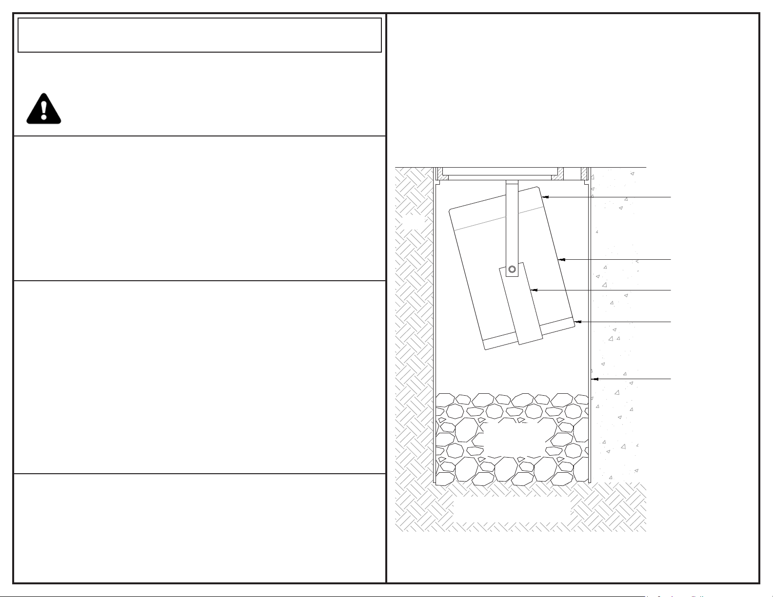
4. Place Tubing into hole with the top of the Tubing ush at grade (Figure 1).
Grade
PLUG
ANGLING
BRACKET
HOUSING
END CAP
BRASS TUBING
Dirt Concrete
(optional)
Pea Gravel
(by others)
Use only dirt or gravel
below fixture for drainage
Figure 1


