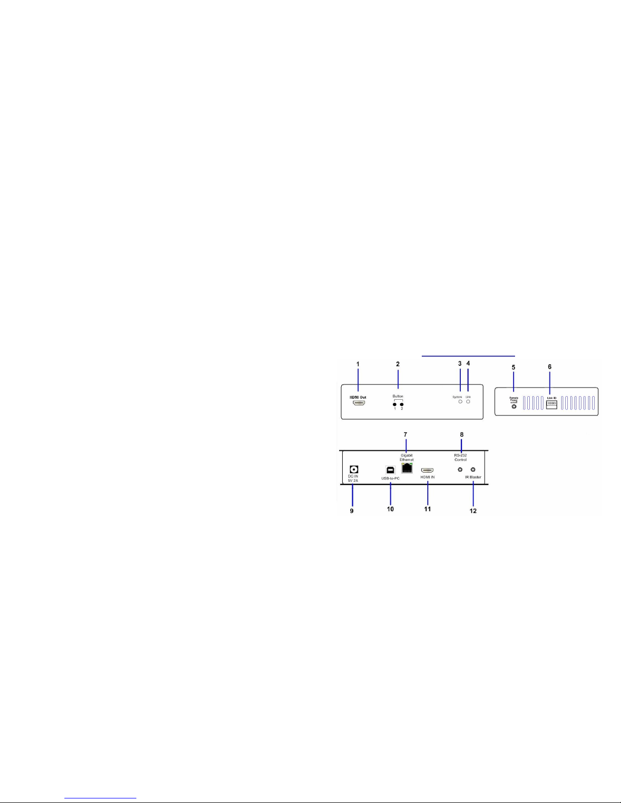
Beacon AV-950R User manual

1
AV-950
HDMI with USB
Over
IP Intranet
(Multi-cast Version)
Installation and User’s Manual
Date: Jan 10, 2010
2
Introduction
The AV-950 system is a perfect solution to extend high resolution
HDMI, USB, and optional IR/RS-232 over IP network. It includes
an AV-950T transmitter and an AV-950R Receiver. The AV-950T
transmitter connects with PC or any device with HDMI source. The
AV-950R receiver connects to HDMI display, speaker, microphone,
USB devices (Keyboard/Mouse/Storage/…) and RS232 devices. It
based on the standard Ethernet Internet Protocol, all of Gigabit or
Fiber LAN switch HUB can be used for inter-connection.
Panel View
AV-950T Transmitter

3
No. Component Description
1 HDMI (or DVI-D)
Loop-back HDMI (or DVI-D) Loop-back for Local Monitor.
Short press Switch video to Remote or
Loopback monitor.
Long press Output video to both Remote
and Loopback monitors.
2 (Button 1) Press and Hold at
Power ON until
Green and Red
LED blinking
Reset the unit to the Factory
default setting
Short press Switch to Video or Graphic
mode
Long press (*)Anti-Dither Mode
2 (Button 2)
Press and Hold at
Power ON until
Green LED blinking Use Loop-back EDID
3 Red LED
(System status)
Green Blinking/Red Off: System is starting up.
Green On/Red Blinking: Linking or waiting HDMI
input.
4 Green LED
(Power/Link
status)
Green On/Red On: Connection established.
5 Remote Power
On/Off (optional) Provide Remote Power On/Off function.
4
6 Link ID
4 bit DIP switch for 16 ID settings. To make
Transmitter/Receiver as a pair or a group, the
transmitter and receiver must be set with the same
Link ID.
7 Gigabit Ethernet Connects to Gigabit switch or directly toAV-950R
8 RS-232 Control
(optional) Provide Serial-over-IP function.
9 DC 5V In System power input port. Connect to a DC 5V 2A
external power adapter.
10 USB-to-PC
Connects this USB-B to PC to provide 2 functions:
1. USB audio device. (An USB audio device will be
detected when it is attached to PC in Windows OS)
2. Virtual 4-port USB Hub for remote USB devices.
11 HDMI IN Connects to HDMI Source. For DVI source, you
may need a HDMI-to-DVI adapter.
12 IR Blaster
(optional) Connects to external IR LED.

5
No. Component Description
1 Green LED
(Power/Link status)
2 Red LED
(System status)
Green Blinking/Red Off: System is starting up.
Green On/Red Blinking: Linking or waiting HDMI
input.
Green On/Red On: Connection established.
3 Link ID
4 bit DIP switch for 16 ID settings. To make
Transmitter/Receiver as a pair or a group, the
transmitter and receiver must be set with the
same Link ID.
AV-950R receiver
6
4 USB Host For remote USB devices, such as USB
KB/Mouse, storage, audio, …
5 IR Rx (optional) Remote Universal IR receiver.
6 Remote Power
On/Off (optional) Provide Remote Power On/Off function.
Short press Switch to Video or Graphic
mode
Long press (*)Anti-Dither Mode
7 Mode button Press and Hold
at Power ON
until Green LED
blinking
Update EDID
Short press Link/Unlink
Long press To gain the USB access right.
8 Link button Press and Hold
at Power ON
until Green and
Red LED
blinking
Reset the unit to the Factory
default setting
9 DC 5V In System power input port. Connect to a DC 5V 2A
external power adapter.
10 HDMI OUT Connect to HDMI display. For DVI display, you
may need a HDMI-to-DVI adapter.
11 RS-232 Control
(optional) Provides Serial-over-IP function.
12 Mic IN Microphone Input for the USB audio device.
(Please set the OS default audio device to the
USB PnP audio device that created byAV-950T)

7
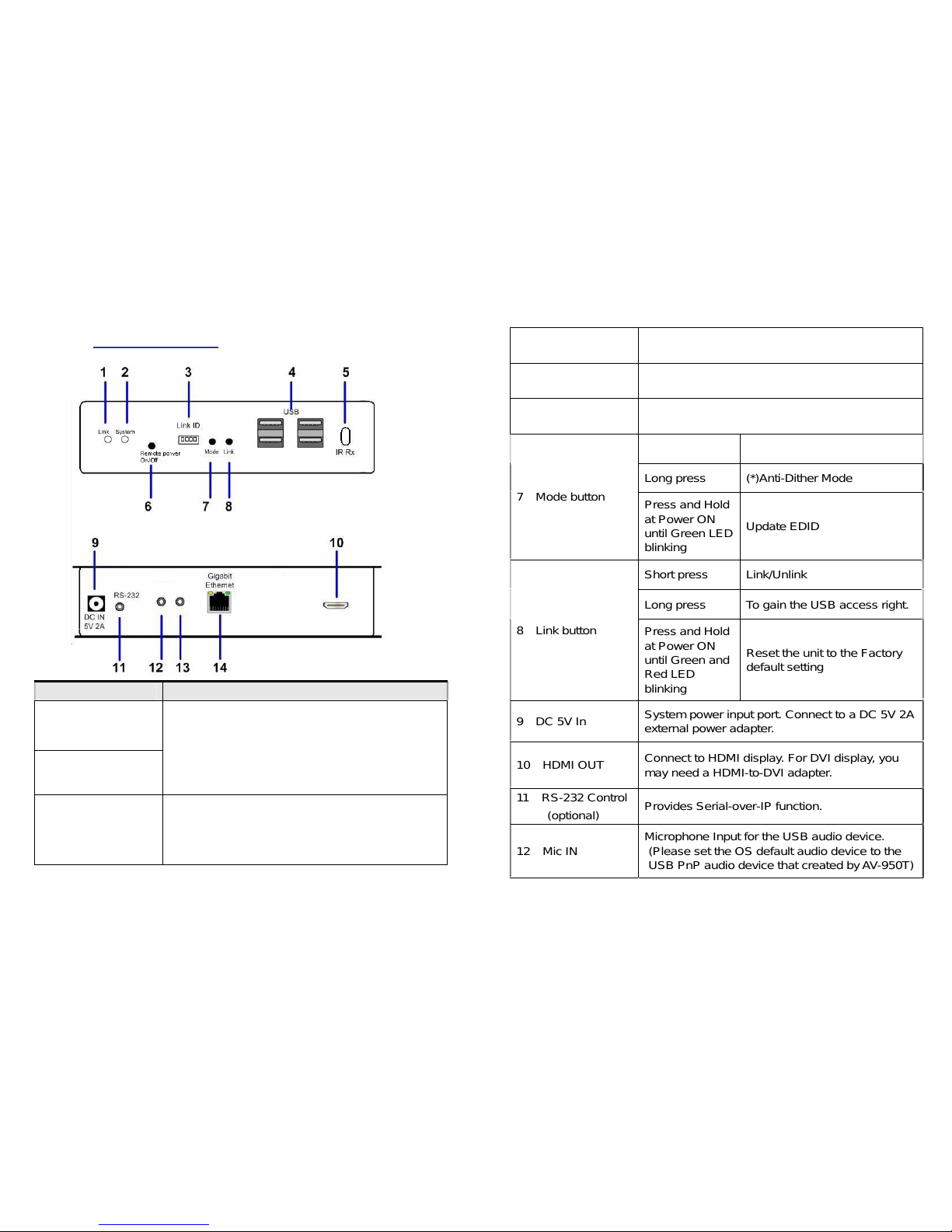
13 Line OUT StereoAudio output for the USB PnP audio
device. (Please set the OS default audio to the
USB PnP audio device that created byAV-950T)
14 Gigabit Ethernet Connects to Gigabit switch or directly to AV-950T
(*) For some of ATI graphic card that with Dithering function
enabled, you may set to “Anti-Dither Mode” to achieve the
better Video quality.
Installation
Please follow the following procedures to install Multi-Cast AVK-950:
1. Make sure the Link-ID both of AV-950T and AV-950R are having the
same setting. They make pair according to this Link-ID setting.
2. Attach your HDMI display to the AV-950R’s HDMI-Out port.
3. Power on the AV-950R, an “AVExtender” logo will be displayed. If
not, then there is something wrong either on the AV-950R or HDMI
cable or HDMI display.
4. You can connect multiple AV-950R and multiple AV-950T units to
your Gigabit Ethernet switch. Or you can also use a CAT5e or
preferred CAT6 UTP cable (straight, EIA 568B) to directly connect a
AV-950T with a AV-950R as a pair connection.
5. Attach your HDMI source (either PC or Blue-ray Disc) to the
AV-950T’s HDMI-In port and then power On the AV-950T.
6. The first AV-950R that being detected by the AV-950T will gain the
USB access right.
7. If you are using PC as your HDMI source, you shall be able to see
your HDMI display EDID information on the PC graphic card control
panel. If not, then there is something wrong either on the AV-950T or
HDMI cable.
8. Output your HDMI (with audio) from your HDMI source and check if
they are correctly displayed on your HDMI display.
8
Please follow the following procedures to install Multi-Cast AVK-950 for
USB over IP:
9. Connect AV-950T’s USB-to-PC port to a Windows based PC USB
port by an USB-A-B cable. You shall see 3 devices are detected:
“Generic USB Hub”, “USB Composite Device”, “USB PnP Sound
Device”.
10. You can select “USB PnP Sound Device” as Windows default sound
device in order to use speaker and microphone on the AV-950R’s
Line-Out (green) and Microphone jack (pink).
11. You can attach USB devices like keyboard, mouse, Pen Drive, audio
speak/microphone … to the AV-950R’s 4 USB-A ports. Please note
that you will need DC 5V with 4A power adapter if all of AV-950R’s 4
USB ports are used.
12. To gain the USB access right among multiple AV-950R, long press
the “Link button” of the AV-950R until an OSD message of
“Requesting USB” displayed then release. An OSD message of
“Starting USB” will be displayed if it successfully gained the USB
access right. Meanwhile, the previous USB Master unit will show an
OSD message of “USB Stopping”.
Setup Operation
1. To Reset the AV-950T to the Factory default setting: Press and Hold
the Button 1 then Power ON until Green and Red LED blinking.
2. To Use the AV-950T Loopback monitor EDID: Press and Hold the
Button 2 then Power ON until Green LED blinking.
3. To update the AV-950R EDID: Press and Hold the Mode button then
Power ON until Green LED blinking.
4. To Reset the AV-950R to the Factory default setting: Press and Hold
the Link button then Power ON until Green and Red LED blinking.
This manual suits for next models
1
Other Beacon Extender manuals