Beale Xpress IA-1250 User manual
IA-1250
12 Channel x 50W Amplifier
User Guide
IA-1250 INTEGRATED AMPLIFIER

2
• Explanation of Graphical Symbols
The lightning flash with arrowhead symbol, within an equilateral triangle, is
intended to alert you to the presence of uninsulated “dangerous voltage” within
the product’s enclosure that may be of sufficient magnitude to constitute a risk of
electric shock to persons.
The exclamation point within an equilateral triangle is intended to alert you to the
presence of important operating and maintenance (servicing) instructions in the
literature accompanying the product.
APPLICABLE FOR USA, CANADA OR WHERE
APPROVED FOR USAGE
CAUTION: TO PREVENT ELECTRIC SHOCK,
MATCH WIDE BLADE PLUG TO WIDE SLOT,
INSERT FULLY.
ATTENTION: POUR EVITER LES CHOCS
ELECTRIQUES, INTRODUIRE LA LAME
LA PLUS LARGE DE LA FICHE DANS LA
BORNE CORRESPONDANTE DE LA PRISE ET
POUSSER JUSQU AU FOND.
RISK OF ELECTRIC SHOCK
DO NOT OPEN
RISQUE DE CHOQUE ÉLECTRIQUE
N'OUVREZ PAS
CAUTION: To reduce the risk of electric shock, do not remove cover (or back).
No user-serviceable parts inside. Refer servicing to qualified service personnel.
1. Read these instructions.
2. Keep these instructions.
3. Heed all warnings.
4. Follow all instructions.
5. Do not use this apparatus near water.
6. Clean only with a dry cloth.
7. Do not block any ventilation openings. Install in accordance with the manufacturer’s instructions.
8. Do not install near any heat sources such as radiators, heat registers, stoves, or other apparatus (including amplifiers) that produce heat.
9. Do not defeat the safety purpose of the polarized or grounding-type plug. A polarized plug has two blades with one wider than the other. A grounding-type plug has
two blades and a third grounding prong. The wide blade or the third prong are provided for your safety. If the provided plug does not fit into your outlet, consult an
electrician for replacement of the obsolete outlet.
10. Protect the power cord from being walked on or pinched particularly at plugs, convenience receptacles, and the point where they exit from the apparatus.
11. Only use attachments/accessories specified by the manufacturer.
12. Use only with the cart, stand, tripod, bracket, or table specified by the manufacturer, or sold with the apparatus. When a cart is used, use caution when moving the
cart/apparatus combination to avoid injury from tip-over.
13. Unplug this apparatus during lightning storms or when unused for long periods of time.
14. Refer all servicing to qualified service personnel. Servicing is required when the apparatus has been damaged in any way, such as power-supply cord or plug is dam-
aged, liquid has been spilled or objects have fallen into the apparatus, the apparatus has been exposed to rain or moisture, does not operate normally, or has been
dropped.
15. The apparatus shall not be exposed to dripping or splashing and that no objects filled with liquids, such as vases, shall be placed on the apparatus.
16. CAUTION: Servicing instructions are for use by qualified service personnel only. To reduce the risk of electric shock, do not perform any servicing other than that con-
tained in the operating instructions unless you are qualified to do so.
17. WARNING: To reduce the risk of fire or electric shock, do not expose this apparatus to rain or moisture.
PORTABLE CART WARNING
Important Safety Instructions

3
Table of Contents
Important Safety Instructions .........................................................................................................................2
Table of Contents ..............................................................................................................................................3
Introduction.......................................................................................................................................................4
Features.............................................................................................................................................................5
What’s Included ................................................................................................................................................5
Front Panel Features ........................................................................................................................................6
Rear Panel Features..........................................................................................................................................7
IR Remote Control.............................................................................................................................................9
Installation ......................................................................................................................................................10
Wiring Infrastructure......................................................................................................................................11
Speaker Wire .............................................................................................................................................11
Multi-zone Audio (4/8Ω) ............................................................................................................................................ 11
Multi-room Audio - Stereo or Bridged (4/8Ω)..................................................................................................... 11
70V/100V....................................................................................................................................................................... 11
Connections.....................................................................................................................................................12
Speaker Connections ................................................................................................................................12
Bridged 8Ω ..................................................................................................................................................................... 12
4Ω/8Ω ............................................................................................................................................................................. 12
70V/100V....................................................................................................................................................................... 13
Audio Connections ....................................................................................................................................14
Zone Line IN................................................................................................................................................................... 14
Audio Bus IN ................................................................................................................................................................. 14
Audio Bus OUT ............................................................................................................................................................. 14
Control Connections..................................................................................................................................15
Zone IR IN ...................................................................................................................................................................... 15
Zone Mute ..................................................................................................................................................................... 16
Zone Status OUT ......................................................................................................................................................... 16
Zone Line/Bus Trigger IN .......................................................................................................................................... 16
Master Control IN ........................................................................................................................................................ 17
Master Control OUT .................................................................................................................................................... 17
RS232 I/O ...................................................................................................................................................................... 17
Settings ...........................................................................................................................................................18
70/V100V High Voltage Speaker Output ............................................................................................................. 18
8Ω/4Ω-70V/100V Zone Setting............................................................................................................................... 18
Stereo/Bridged Zone Setting ................................................................................................................................... 18
Limiter............................................................................................................................................................................. 18
Remote Bypass............................................................................................................................................................ 19
Voltage Select/Fuse.................................................................................................................................................... 19
Operation.........................................................................................................................................................21
Voltage Controlled....................................................................................................................................................... 21
IR Controlled.................................................................................................................................................................. 21
RS232 Controlled......................................................................................................................................................... 22
RS232 Commands...........................................................................................................................................23
RS232 Queries.................................................................................................................................................25
RS232 Settings................................................................................................................................................27
Specifications..................................................................................................................................................29
Limited Warranty............................................................................................................................................30

4
Introduction
Congratulations and thank you for purchasing the Beale Street Xpress IA-1250 12 Channel Amplifier.
The IA-1250 is, at its core, a twelve channel audio distribution amp. Snore...
That's why the IA-1250 does so much other stuff!!! OK. Yes, it is a twelve channel audio distribution amp
that can be configured for six stereo 4Ω/8Ω zones (30W/channel @ 8Ω; 50W/channel @ 4Ω); but it can also
be configured for six stereo 70/100V zones (30W/channel); or three high powered bridged zones (100W
@ 8Ω). By the way, the IA-1250 can be configured for any combination of stereo 4Ω/8Ω, 8Ω bridged and
70/100V zones all at the same time! That's some stuff, right?
But there's more...each zone can be controlled via IR or RS232 for ON/OFF, Input, Volume/Mute, Treble/
Bass and Left/Right Balance. The RS232 section is bi-directional with easy to configure command
structure. IA-1250 can be configured to automatically send zone status updates or respond to queries to
confirm zone status and settings. Commands for volume, treble/bass and balance can be specific values or
step commands depending upon the control application.
The IA-1250 has an Audio Bus IN that can be manually selected by IR commands, RS232 commands or
voltage trigger. The voltage trigger will switch a zone to the Audio Bus IN as long as there is voltage present
on the zone Line/Bus Trigger IN. When the voltage is cut, the zone automatically switches back to the zone
Line IN. Great for momentary switching to an audio page on the Bus IN!
Each zone has a Mute Trigger IN that will mute zone audio when voltage is present on the Mute Trigger IN.
When the voltage is cut, the zone audio output resumes.
Each zone has a 12VDC Status or Control OUT that can be used to activate a zone specific volatge
controlled device or otherwise indicate zone ON/OFF status.
Each zone has a -20dB audio limiter to prevent incidental peaks from becoming irrevocable problems.
The IA-1250 features a Remote Bypass switch that allows/blocks IR and RS232 from select zones for
zones that are intended to be set and not messed with.
Finally, the IA-1250 can has a 110~120V/220~240V select switch allowing it to be used just about
anywhere there is AC Voltage.
What? Yes of course it's rack mountable and comes with removable rack ears.
The Beale Street Xpress IA-1250 12 channel x 50W audio distribution amp...ready for anything...anywhere.
Please read and follow the instructions in this guide to assure proper installation and maximum
performance of your new Beale Street Xpress IA-1250.

5
Features
• Each zone can independently select a zone-specific stereo audio source or the global mono Audio Bus
input (unbalanced)
• Each zone can be independently configured for stereo 4Ω/8Ω mode, high powered bridged 8Ω mode or
70V/100V mode for total flexibility within a given installation
• All zones are independently controllable via RS232, IR and voltage trigger lines
• Each zone has -20dB Audio Limiter
• Each zone has an independent mute trigger input (activated by +3 to +30V DC)
• Each zone has an individual Trigger Output (+12V DC) that coresponds to zone ON/OFF status
• Front panel features “Zone ON” and “Zone Overload” LED indicators for each zone
• Master global Control In (+3 to +30V DC) and Control Out (+12V DC)
• Detachable screw-terminal connectors for global Audio Bus IN/OUT, Zone IR IN, Zone Mute, Zone Status
OUT and Zone Speaker Outputs
• Rack mountable in standard 19" rack (2U height)
• Selectable 110/220 AC volatge
What’s Included
1 - IA-1250 Amplifier
1 - IR Remote
1 - AC Power Cord
1 - Owner’s Manual
6
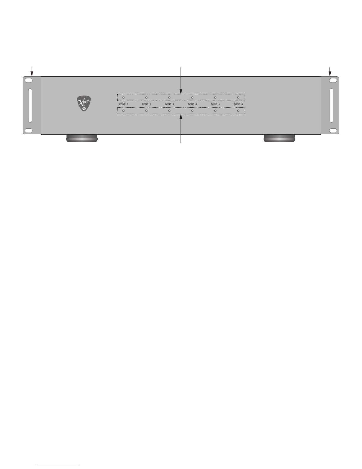
This is the stuff on the front panel...
IA-1250 INTEGRATED AMPLIFIER
21 1
3
1. RACK EARS - Two, optional rack ears for optional rack mounting...see where this is going? The IA-1250
is 2U rack height. If rack mounting, leave one rack space above and below for air flow. The rack ears can
be removed for shelf mount if desired. (OK. So they’re not necessarily on the front panel, but you can
see them from here.)
2. PEAK OUTPUT LEDS - Six, red LEDs indicate that the amplifier is within 5% of the maximum volume
setting. This is an indication that the volume setting is approaching maximum...not an indication of the
specific power output. To be safe, when this LED illuminates, back the volume off a bit to protect the
amp, speakers and probably your hearing.
3. ZONE POWER LEDs - Six, green LEDs illuminate solid green when a stereo zone is ON. LED turns OFF
when Zone is OFF.
Front Panel Features

7
This is the stuff on the rear panel...
Right Left
Right Left
Right Left
Right Left
Right Left
Right Left
12 3 4 5 6 7 8 9
1011121314151617
1. SYSTEM 70/100 VOLT SELECT - One, switch. Slide switch to select between 70V and 100V for a high-
voltage audio distribution system. This setting will affect all zones in 70V/100V mode. Set for 70V when
voltage select is set to 110-120VAC; Set for 100V when voltage select is set to 220-240VAC.
2. ZONE IR, MUTE & STATUS TERMINAL - Six, plug-in screw terminals. Provides connections for zone
specific IR control, mute and status.
IR IN - Connect IR IN & GND to the Emitter OUT on an Xpress IR Control system for zone IR control
using the IA-1250 IR Remote.
Mute - Connect to a +3 to +30VDC @1mA control voltage to mute the local zone.
Status - Provides a 12VDC 1mA Control OUT to trigger zone specific voltage controlled devices.
3. ZONE SPEAKER TERMINAL- Six, plug-in screw terminals. Each terminal has six connections for different
speaker output configurations including:
Bridge 8Ω - Use indicated terminals for high output mono speaker connection. (100W @ 8Ω)
NOTE 1: 8Ω/4Ω - 70V/100V switch must be in the OUT position.
NOTE 2: The Stereo/Bridged switch must be in the IN (Bridged) position.
4Ω/8Ω - Use indicated terminals for normal stereo speaker connections. (30W @ 8Ω; 50W @ 4Ω)
NOTE 1: 8Ω/4Ω - 70V/100V switch must be in the OUT position.
NOTE 2: The Stereo/Bridged switch must be in the OUT (Stereo) position.
70V/100V - Use indicated terminals for 70V/100V stereo speaker connections. (30W @ 70V/100V)
NOTE 1: 8Ω/4Ω - 70V/100V switch must be in the IN position.
NOTE 2: 70V/100V High Voltage Speaker Output Switch must be set to proper voltage.
NOTE 3: The Stereo/Bridged switch must be in the OUT (Stereo) position.
4. ZONE LINE/BUS TRIGGER IN- Six, 3.5mm mini jacks. This voltage controlled input switches the zone
audio input from Line IN to Audio Bus IN. When there is no voltage applied, the zone audio input is zone
Line IN. When voltage is applied (+3 to +30VDC @1mA) the zone audio input will switch to Audio Bus IN.
5. ZONE 8Ω/4Ω - 70V/100V SWITCH - Six, push buttons. Press to select 8Ω/4Ω - 70V/100V by zone. Leave
OUT to select 8Ω/4Ω, press IN to select 70V/100V.
6. MASTER CONTROL IN - One, 3.5mm mini jack. Connect to a +3 to +30VDC @1mA control voltage to
turn the IA-1250 ON.
NOTE: Power ON/OFF switch must be in the OFF position when using this feature.
Rear Panel Features

8
7. MASTER CONTROL OUT - One, 3.5mm mini jack. Connect to any voltage controlled device that is to be
turned ON/OFF relative to IA-1250 ON/OFF Status. When any zone on the IA-1250 is ON the Master
Control OUT will output 11.5VDC@1mA-10VDC@5mA. When all zones are OFF the Master Control OUT
is 0.0VDC.
8. POWER ON/OFF SWITCH - One, switch. Set to ON position to turn power to the amp ON. Set to OFF
position to turn power to the amp OFF.
9. VOLTAGE SELECT SWITCH - One, switch. Select either 110V-120V or 220V-240V as appropriate for
local AC line voltage. Please confirm local voltage prior to use or making changes to the setting.
10. AC MAINS - One, three-prong socket. Use the supplied 3-pin ground power cable to connect the unit to
an external AC power supply.
11. FUSE - One, replaceable fuse. For 110V-120V/60Hz use T10.0AL/250V fuse. For 220V-240V/50Hz use
T5.0AL/250V fuse.
12. RS232 TERMINAL - One, DB9F terminal. Connect to an automation system or other controller for two-
way communication with and control of the IA-1250.
13. REMOTE BYPASS - One, six position DIP switch. Set to OFF to allow IR/RS232 control of the selected
zone. Set to ON to block IR/RS232 control of the selected zone.
14. ZONE LINE IN - Twelve, RCA jacks. Connect to the L & R line level OUTs on an audio source that is to be
dedicated to the local zone.
15. ZONE AUDIO LIMITER - Six, push buttons. Press to activates a -20dB input limiter, for both channels, to
help reduce the level of accidental audio peaks and clipping distortion by zone. Leave in the OUT position
to pass audio through unprocessed, press IN to activate the input limiter.
16. STEREO/BRIDGED - Six, push buttons. Sets zone amplifier output to stereo/bridge mode. This switch
works in conjunction with the zone speaker connections and 8Ω/4Ω - 70V/100V switch position.
Please see sections: Zone Speaker Terminal and 8Ω/4Ω - 70V/100V Switch, previous, for important
information.
Stereo - For stereo signals, leave switch in the OUT (Stereo) position. This applies to all connections
in the 8Ω/4Ω and 70V/100V configurations.
Bridged - ONLY press this button when using the BRIDGE 8Ω connections in a given zone.
CAUTION: In Bridged mode, the amplifier will encounter a load that is about one half of its actual
value. A 4Ω load would therefore be 2Ω to a bridged amp and if the amplifier isn’t designed to run
safely into such a low impedance (which the IA-1250 is not) damage may occur to the amplifier.
DO NOT CONNECT A 70V SPEAKER CIRCUIT WHILE IN BRIDGE MODE. The output will be 140V,
well beyond spec for a 100V system. Any damage to the amplifier caused by this configuration is
not covered under warranty.
17. AUDIO BUS - One, plug-in screw terminal. Mono, unbalanced input. This input will send the Audio IN
signal to all zones switched to Bus using the Line/Bus Trigger IN. It will also send the Bus Audio IN
signal to another IA-1250 via the Audio Bus OUT.
Rear Panel Features
9
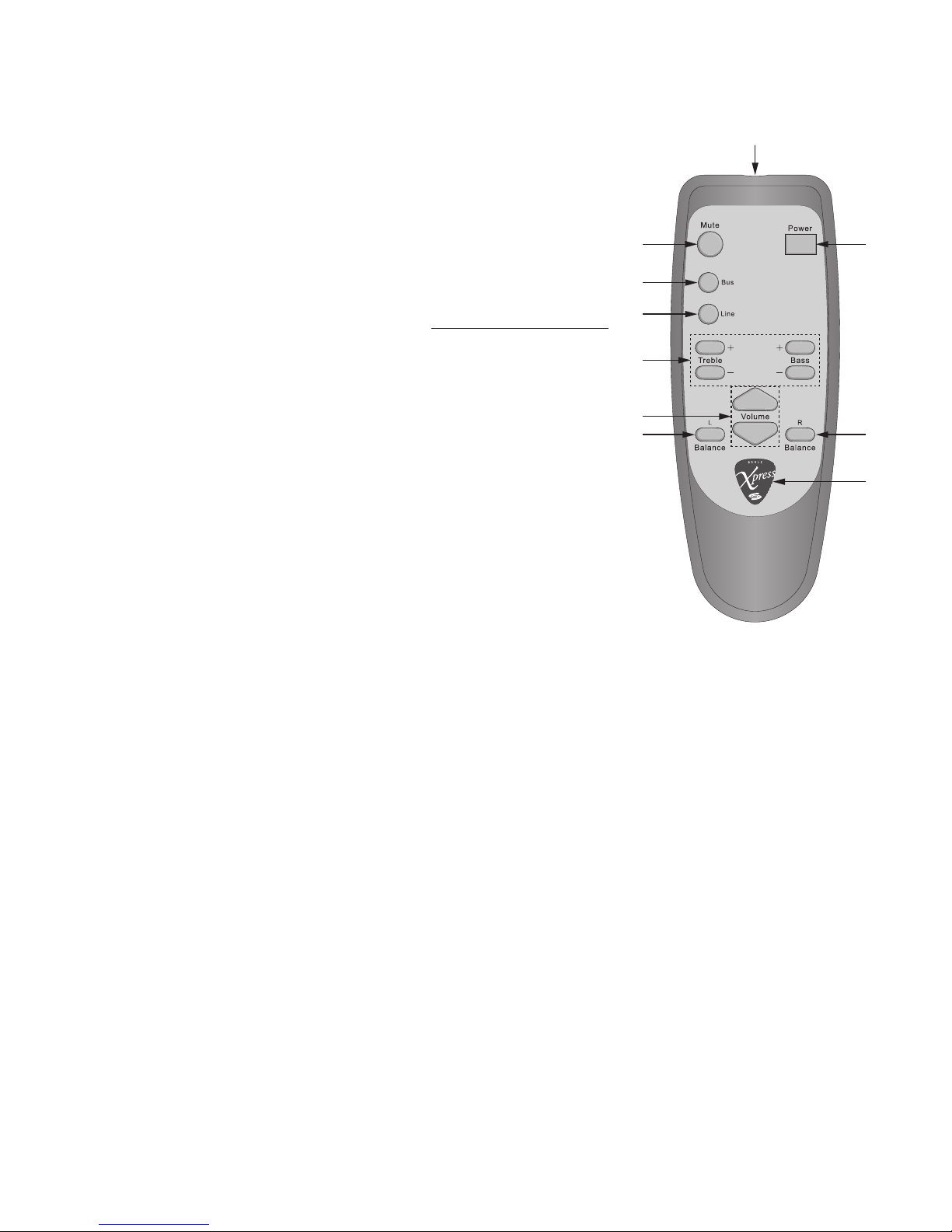
IR Remote Control
The IA-1250 IR Remote Control, believe it or not, controls the IA-1250.
Actually, it controls the individual zones on the IA-1250, and will more
than likely be used to program some sort of programmable, integrated
IR remote, zone control system or other IR routing device.
All zones are configured for the same codes, so use of a multi-zone
controller or IR router will be necessary for centralized control of the
individual zones. Local zone control can be easily accommodated with
a local IR receiver, (we make those...please visit www.bealexpress.com
for additional information.) and an IR Remote.
1. IR LED - One, high-output IR LED. The IR LED flashes invisible
(infrared) light pulses that are the control codes for the IA-1250.
The LED must be pointed at an IR receiver (we make those...oh...
that's right...we already mentioned that) that is connected to an
IA-1250 Zone IR IN.
2. MUTE - With audio playing in a zone, press this button to mute the
zone audio output. Press again to un-mute.
3. BUS - Press this button to select the audio source playing through
the Audio Bus IN.
1
2
3
4
5
6
7
8
7
9
4. LINE - Press this button to select the audio source playing through the local zone Line IN.
5. TREBLE/BASS - Press the Treble +/- buttons to increase/decrease the accent of high frequencies in the
zone audio output. Press the Bass +/- buttons to increase/decrease the accent of low frequencies in the
zone audio output. Season to taste.
NOTE: Reset to flat requires issuing an RS232 command to the zone via the RS232 terminal. See
sections: RS232 Commands and IA-1250 Treble/Bass Settings for additional information.
6. VOLUME - Press the Volume + button to increase zone audio output. Press the Volume - button to
decrease zone audio output.
7. BALANCE L/R - Press the Balance L button to increase volume in the left speaker relative to the right
speaker. Press the Balance R button to increase volume in the right speaker relative to the left speaker.
NOTE: Reset to center default requires issuing an RS232 command to the zone via the RS232 terminal.
See sections: RS232 Commands and IA-1250 Left/Right Balance Settings for additional information.
8. POWER - Yeah...yeah...this button should have been listed first...press this button to turn the local zone
ON. Press again to turn the local zone OFF.
9. BEALE STREET XPRESS LOGO - No function specific to the remote, but we like the guitar pick shape,
fancy script Xpress and Sonic Vortex symbol, so we just thought we'd mention it.

10
Installation
Here's a few things to consider when installing the IA-1250...
IA-1250 INTEGRATED AMPLIFIER
1U Rack Vent Above IA-1250
1U Rack Vent Below IA-1250
1. The IA-1250 is convection cooled. It depends on the natural free flow of air up through the slot
perforations in the bottom plate, over the internal heat dissipating fins, then out the top cover, for
adequate cooling.
2. The IA-1250 is designed for mounting into standard 19" (483mm) racks or on flat horizontal surfaces.
3. If mounted in an equipment cabinet or other confining location, allow at least 2 inches of space above
the top cover. Be sure there are large openings in the shelf below the unit and in the cabinet to allow the
entry of cool air and the escape of warm air.
4. If the cabinet contains other heat generating components or several IA-1250’s are being used, be sure
to provide adequate ventilation to dissipate heat the units can generate.
5. Use fans (quiet, boxer type), if necessary, to ensure a constant flow of air through the IA-1250's and the
other heat generating components.
6. When installing the IA-1250 in a rack, please use racks that feature a rear support provision. Adding
a single RU (Rack Unit) vent above and below the IA-1250 will improve convection in heavy use
applications. [One Rack Unit size = 1-3/4" (44.5mm) in height]. Also try to mount the amplifier(s) at the
top of the rack so heat dissipation does not affect other devices.
7. Be sure to leave adequate space for large bundles of wire and dress them in such a manner that does
not block airflow. Leave enough 'play' in the wires for making connections should the system require
service.

11
Wiring Infrastructure
Now for a few simple guidelines on wiring...
Speaker Wire
The IA-1250 is a flexible multi-channel amplifier capable of many different applications. The application
for a given system, or even different amp configurations for different zones in a single system can create
different requirements for speaker wire runs. Please review the information below and apply these
guidelines to your particular application(s).
MULTI-ZONE AUDIO (4/8Ω)
If the IA-1250 is being used with a multi-zone preamp/controller then pull the home-runs directly from the
speaker locations or speaker terminal plates to the amplifier location. Use quality stranded speaker wire
based upon the 4/8Ω Speaker Wire Gauge Table below.
MULTI-ROOM AUDIO - STEREO OR BRIDGED (4/8Ω)
If the amp is being used to distribute audio from the IA-1250 Zone Line INs or Audio Bus IN, to different
rooms with 4/8Ω Speakers, individual room volume controls (or an IR control system) will be needed.
(Please visit www.bealexpress.com for additional information.) In this application pull speaker wire from
each speaker to the volume control location in each room and then home-runs from each volume control
to the amplifier location. Use quality stranded speaker wire based upon the 4/8Ω Speaker Wire Gauge Table
below.
4/8Ω SPEAKER WIRE GAUGE
SPEAKER WIRE LENGTH SPEAKER WIRE GAUGE
150’ (46m) 16 AWG
400’ (122m) 14 AWG
1000’ (305m) 12 AWG
70V/100V
If the amp is being used to distribute 70V/100V audio, pull distribution lines (each distribution line is a wire
pair) in a daisy-chain pattern, (amp to first speaker, first speaker to second speaker, second speaker to third
speaker, etc.) If distributing stereo, pull two distribution lines (two pair) to each speaker location in a daisy
chain from the amp location. Use quality stranded speaker wire based upon the 70V Speaker Wire Gauge
Table below.
70V SPEAKER WIRE GAUGE (30W Zone Output)
SPEAKER WIRE LENGTH SPEAKER WIRE GAUGE
350’ (106m) 24 AWG
550’ (167m) 22 AWG
900’ (274m) 20 AWG
1400' (426m) 18AWG
2300' (701m) 16AWG
12
Connections
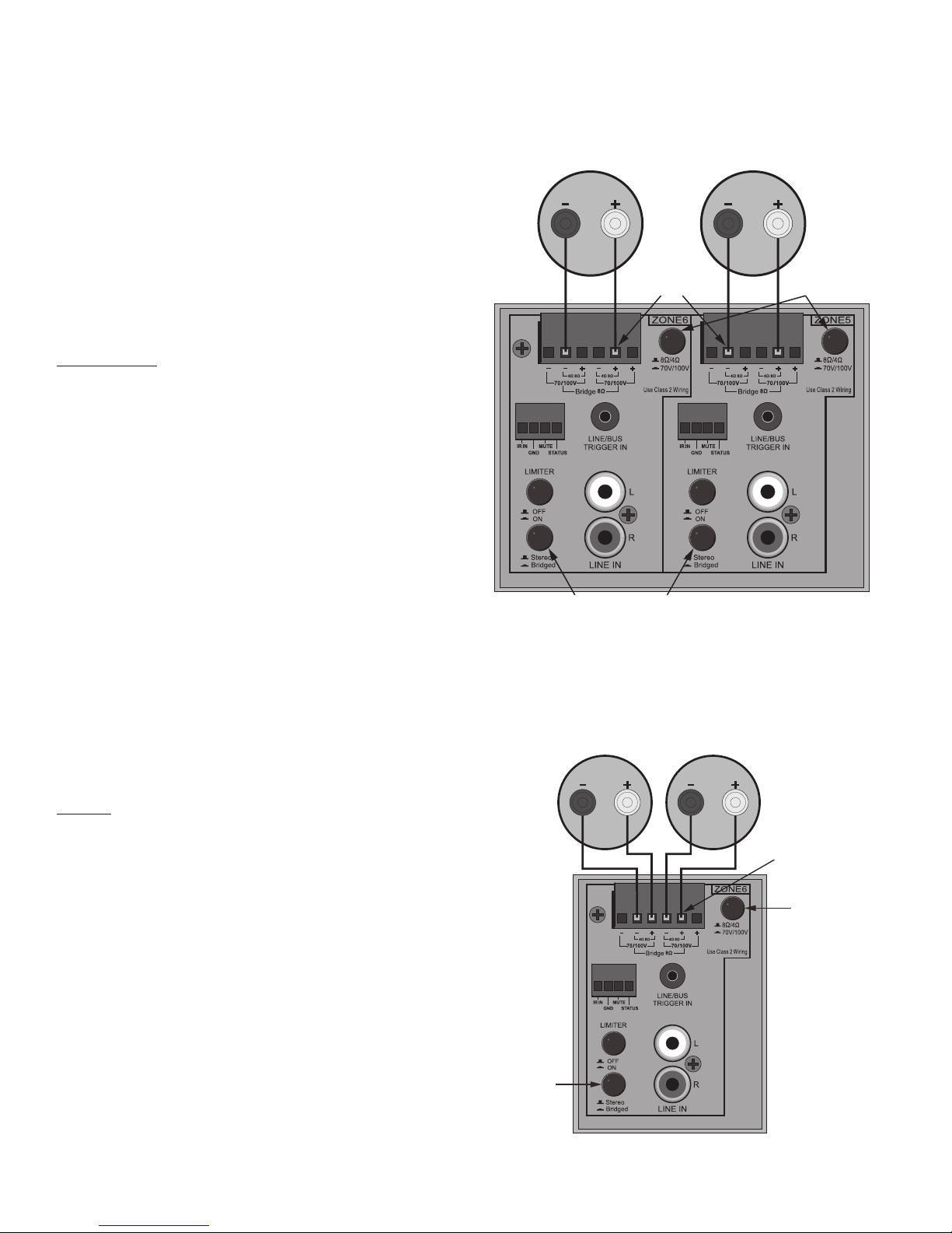
Speaker Connections
The IA-1250 has three amplifier modes for zone
speaker connections. Bridged 8Ω, 4/8Ω Stereo and
70V/100V. Any mix of amplifier modes is allowable
in different zones...as long as they are configured
correctly. In all cases, connect speakers after all
switch changes have been made to protect the amp
and speakers!
BRIDGED 8Ω
Bridging a zone amp creates an 8Ω,110 Watt mono
amplifier. You will need to use two bridged zones for
stereo.
1. Stereo/Bridged Switch - Set to the Bridged
position.
2. 8Ω/4Ω-70V/100V Switch - Set to the 8Ω/4Ω
position.
3. Speaker Connections - Connect the wire from the
speaker - terminal to the Bridge 8Ω - terminal as
shown in: Bridged 8Ω Connection. Connect the
wire from the speaker + terminal to the Bridge 8Ω
+ terminal as shown in: Bridged 8Ω Connection.
4. Zone Line IN - Connect the source left channel
OUT to the left channel Line IN on the LOWER
NUMBERED bridged zone. Connect the source
right channel OUT to the left channel Line IN on
the HIGHER NUMBERED bridged zone.
4Ω/8Ω
This configuration creates a standard zone stereo
speaker output. (30W @ 8Ω/50W @ 4Ω)
1. Stereo/Bridged Switch - Set to the Stereo
position.
2. 8Ω/4Ω-70V/100V Switch - Set to the 8Ω/4Ω
position.
3. Speaker Connections - Connect the wire from
the right speaker - terminal to the right 4/8Ω -
terminal as shown in: Stereo 4/8Ω Connection.
Connect the wire from the right speaker +
terminal to the right 4/8Ω + terminal as shown
in: Stereo 4/8Ω Connection. Repeat for the left
channel speaker.
4. Zone Line IN - Connect the L & R line level OUT on
the zone audio source to the appropriate zone L &
R LINE IN.
High Power
8Ω Speaker
Right LeftRight Left
High Power
8Ω Speaker
8Ω/4Ω
70V/100V
Set to: 8Ω/4Ω
Stereo/Bridged
Set to: Bridged
Bridge 8Ω
-/+ Terminals
Right Left
Medium Power
4/8Ω Speaker
8Ω/4Ω
70V/100V Switch
Set to: 8Ω/4Ω
Stereo/Bridged
Switch
Set to: Stereo
4/8Ω
-/+ Terminals
Right Left
Bridged 8Ω Connection
Stereo 4/8Ω Connection
13
Connections
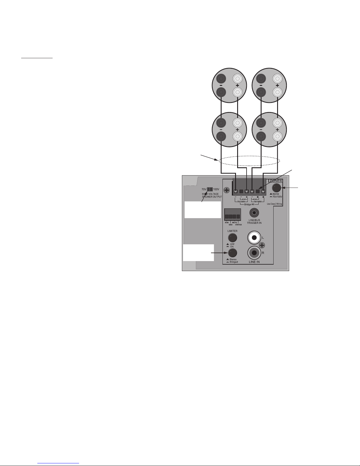
70V/100V
This configuration creates a stereo 70V speaker
zone. (30W/channel) A 70V/100 V system utilizes
speakers with special taps that set the wattage/
volume of each speaker.
70V/100V speaker system are wired using a daisy-
chain configuration where the amp feeds a speaker,
then that speaker connects to the next speaker and
so on.
When setting a IA-1250 zone for 70V/100V, be
sure to accurately calculate the total wattage
required and not exceed the IA-1250 70V/100V
zone's output, 30W per channel in 70V/100V mode.
Typically 70V amp power requirement can be
calculated by adding the total of the tap wattage
set for all speakers to be connected to a 70V/100V
zone and multiplying it by 1.2. This will allow
roughly a 20% loss of efficiency, typical for this type
of system.
If the total wattage exceeds 30 Watts for a
70/100V zone, reduce the load to any given zone by
connecting 70V/100V speakers to multiple zones
set to 70V/100V to safely distribute the load.
Right Left
Low/Medium Power
70V/100 Speakers
8Ω/4Ω
70V/100V Switch
Set to: 70V/100V
Stereo/Bridged
Switch
Set to: Stereo
70V/100V
-/+ Terminals
Right Left
Right Left
70V Speaker
Parallel IN/OUT
70V Speaker
Parallel IN/OUT
IN
OUT
IN
OUT
70V/100V
Distribution Lines
Set 70V/100V
for all 70V/100V
Zones. See text.
1. 70V/100V High Voltage Speaker Output - Set to 70V if IA-1250 AC Voltage Select switch is set to
110~120VAC. Set to 100V if IA-1250 AC Voltage Select switch is set to 220~240VAC. This setting will
affect all zones set to 70V/100V.
1. Stereo/Bridged Switch - Set to the Stereo position.
2. 8Ω/4Ω-70V/100V Switch - Set to the 70V/100V position.
3. Speaker Connections - Connect the right 70V distribution line +/- wires to the right 70V/100V +/-
terminals as shown in: 70V/100V Connection. If configuring stereo, Repeat for the left channel speaker.
Connect the right channel +/- distribution lines to the IN terminals on the first 70/100V speaker. Repeat
for the left channel.
Connect the right/left channel +/- distribution lines to the OUT terminals on the first 70/100V speaker.
Connect the right/left channel +/- distribution lines to the IN terminals on the next 70/100V speaker.
NOTE 1: Speaker terminals may not be specifically marked IN/OUT.
NOTE 2: In a 70/100V system +/- polarity is not critical in same way as in a 4/8Ω system. But it is
critically important that the connections be consistent, that is, plus to plus, minus to minus.
4. Zone Line IN - Connect the L & R line level OUT on the zone audio source to the appropriate zone L &
R LINE IN.
70V/100V Connection
14
Connections
Other Connections
...and this would be all the other stuff that needs to get
connected...
Audio Connections
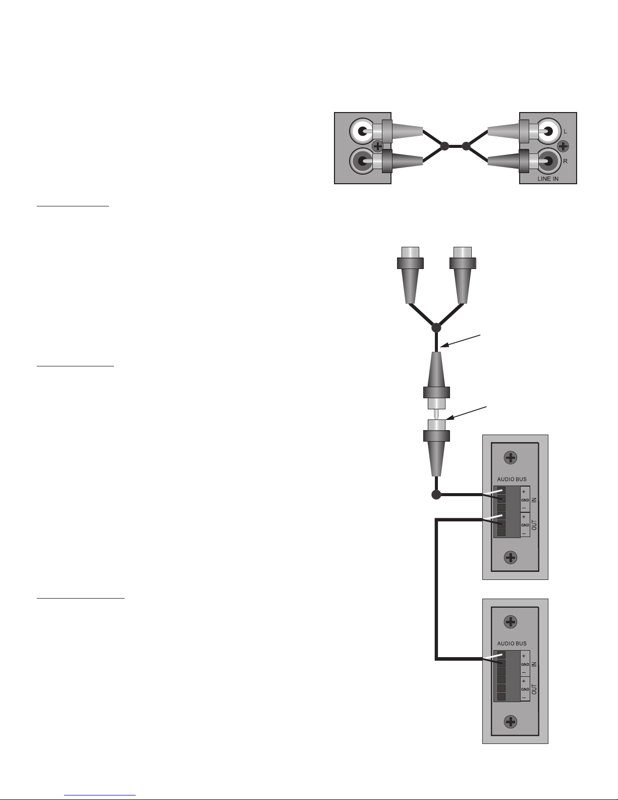
ZONE LINE IN
This connection is an input for a dedicated zone line-
level audio source. If multiple line level audio sources
are required in a zone, use an audio switch on the zone
Line IN or use a multi-source, multi-zone controller if
multiple audio sources are required in multiple zones.
1. Line IN - Using a quality, stereo audio RCA-RCA
patch cable with gold ends, connect the L&R line
level OUTs on the audio source to the L&R Line INs
on the appropriate IA-1250 zone.
AUDIO BUS IN
This connection will distribute unbalanced line level
audio to any zone set to 'Bus' with the Line/Bus Trigger
IN.
NOTE: This is a mono unbalanced line level input. If
connecting a stereo line level device, use an appropriate
stereo to mono adapter as shown when making this
connection.
1. IN - Connect the RCA to bare wire adapter to the
Audio Bus IN +/GND terminals as shown.
2. Connect the Audio Bus IN Source to the RCA
adapter. Use a stereo to mono adapter if connecting
a stereo source.
NOTE: Polarity of RCA plugs/jacks is typically pin =
signal, sleeve =GND.
AUDIO BUS OUT
This connection will send the unbalanced line level
audio source connected to the Audio Bus IN to the
Audio Bus IN on another IA-1250 or other audio
amplifier.
1. OUT - Using either the RCA adapter or bare wire,
connect the Audio Bus OUT +/GND terminals on IA-
1250 #1 to the Audio Bus IN +/GND terminals on
IA-1250 #2.
NOTE: Polarity of RCA plugs/jacks is typically pin =
signal, sleeve =GND.
Optional
RCA Stereo to Mono
Adapter
(Not Included)
Connect to Line Level
Stereo Audio Source
Connect to Line Level
Mono Audio Source
IA-1250 #1
IA-1250 #2
Jump IA-1250 #1
Audio Bus OUT to
IA-1250 #2
Audio Bus IN
RCA to
Bare Wire
Adapter
(Included)
Audio Bus IN/OUT Connections
LINE OUT
L
R
Stereo Line Level
Audio Source
IA-1250 Zone
Line IN
RCA Stereo
Patch Cable
Zone Line IN Connections
15
Control Connections
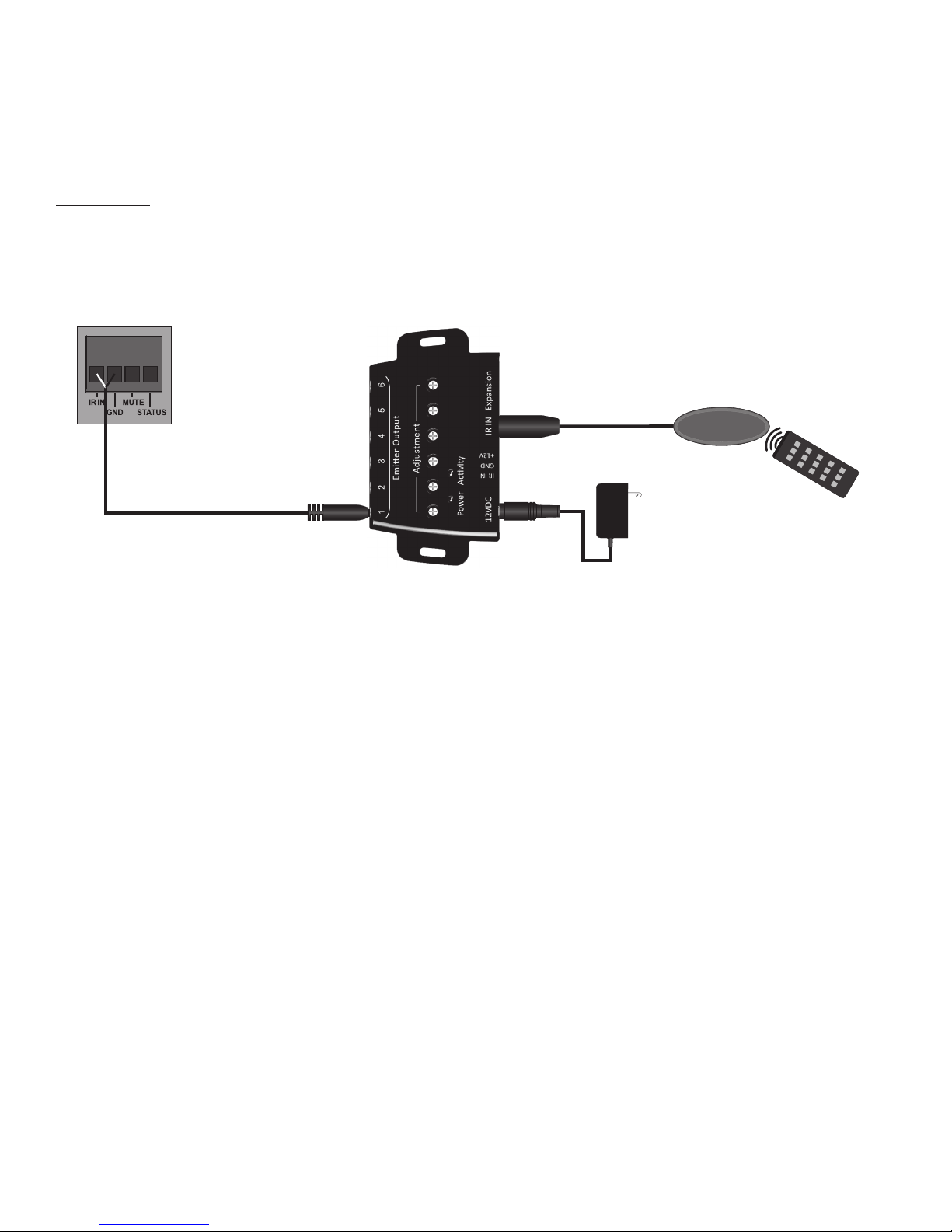
ZONE IR IN
This connection allows IR control of the connected zone for zone power, volume, mute, Line/Bus, etc using
the commands from the IA-1250 IR Remote and a connected IR control system.
Beale IRST IR Receiver
Beale IRB6 Connecting Block
12VDC
Power Supply
IR Remote
IA-1250 Zone IR Input
1. IR/GND - Using a 2-circuit 3.5mm mini plug cable, connect the IR Emitter OUT of an Xpress or other
IR control system to the IR IN and GND terminals on the appropriate IA-1250 zone. Connect the white
stripe (tip) to IR IN, connect the black (sleeve) to GND.
NOTE: Polarity of IR Emitter 3.5mm plugs/jacks is typically tip = signal, sleeve =GND.
Connections
Zone IR Connections
16
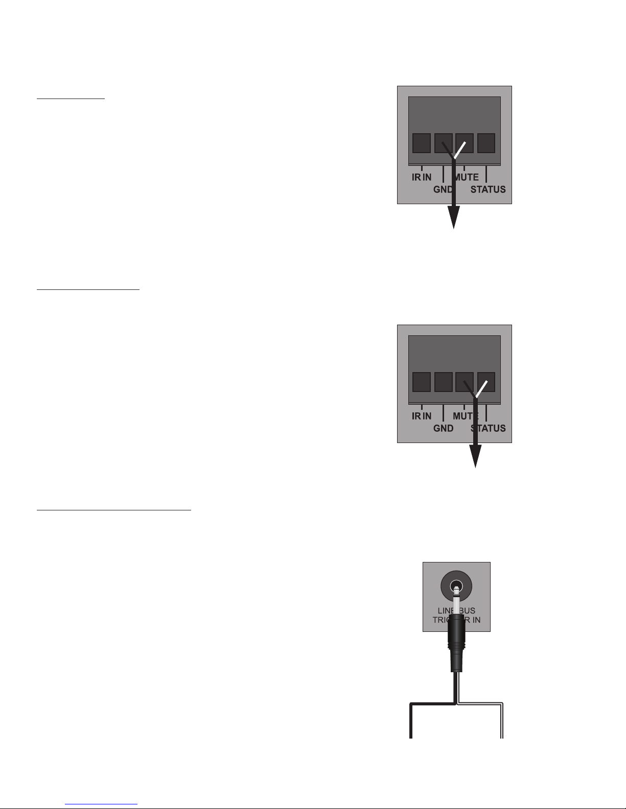
ZONE MUTE
This connection allows voltage control of zone mute.
Applied voltage (+3 to +30VDC @1mA) will mute the
zone speaker output. When the voltage is cut, zone
speaker output is restored.
1. MUTE/GND - Using a 2-conductor stranded, non-
shielded cable, connect +DC voltage and GND from
the trigger device to the MUTE and GND terminals
on the appropriate IA-1250 zone. Connect +VDC to
MUTE, connect GND to GND.
ZONE STATUS OUT
This connection provides a +12VDC 1mA zone control
output that can be used to trigger zone specific, voltage
controlled devices. When an IA-1250 zone is ON, this
connection will output a +12VDC control voltage. When
the zone is OFF the control voltage is 0.OVDC
1. Status/GND - Using a 2-conductor stranded,
non-shielded cable, connect STATUS (+DC voltage)
and GND from the IA-1250 zone to the Control
IN (+VDC) and GND terminals on the device to be
controlled. If the controlled device uses a jack,
please refer to the product's owner's manual to
confirm the polarity of the connection.
ZONE LINE/BUS TRIGGER IN
This connection provides a voltage trigger to switch the
zone audio input from Line IN to Audio Bus IN. When
there is no voltage applied, the zone audio input is zone
Line IN. When voltage is applied the zone audio input
will switch to Audio Bus IN...an excellent option for
audio page override.
1. Line/Bus - Using a 2 circuit 3.5mm mini plug,
connect the voltage trigger to the appropriate
zone Line/Bus Trigger IN. Connect +12VDC from
the trigger device to the striped wire (tip). Connect
GND from the trigger device to the unmarked wire
(sleeve).
To +V/GND
on Trigger Device
To +V/GND
on Voltage Controlled Device
+12VDC
(Tip)
2 Circuit
Mini plug
GND
(Sleeve)
Stripe
Zone Mute Connection
Zone Voltage Control Connection
Zone Line/Bus Trigger Connection
Connections
17
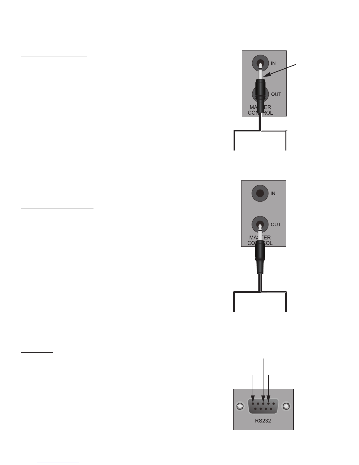
MASTER CONTROL IN
This connection allows voltage control of IA-1250 ON/
OFF. Applied voltage (+3 to +30VDC @1mA) will turn
the amp ON. When voltage is cut, the amp will turn
OFF. (OFF, not Standby.)
NOTE: The Power Switch must be in the OFF position
when using this feature. With this feature the IR and
RS232 controls will not turn a zone ON or have any
other control unless proper voltage is applied to the
Control IN.
1. Master Control IN - Using a 2 circuit 3.5mm mini
plug, connect the voltage trigger to the Master
Control IN. Connect +3 to +30VDC @1mA from
the trigger device to the striped wire (tip). Connect
GND from the trigger device to the unmarked wire
(sleeve).
MASTER CONTROL OUT
This connection provides a voltage control OUT that
can be used for triggering voltage controlled system
devices that need to be turned ON when any IA-1250
zone is active. When any IA-1250 zone is ON, the
Master Control OUT will output +11.5VDC@1mA-
10VDC@5mA. If all zones are OFF, the Master Control
OUT will output 0.0VDC.
1. Master Control OUT - Using a 2 circuit 3.5mm mini
plug, connect the IA-1250 Master Control OUT to
the voltage controlled device(s). Connect the striped
wire (tip) to +12VDC on the controlled device.
Connect GND the unmarked wire (sleeve) to GND on
the controlled device.
RS232 I/O
This connection provides a two-way communication
terminal for control/status feedback of the IA-1250
from/to an automation system or other appropriately
capable device.
1. RS232 - Using a DB9 Patch Cable, connect the
IA-1250 RS232 Terminal to an appropriate RS232
terminal on an automation system controller or
other device. IA-1250 RS232 DB9F pin-out is as
shown. Please refer to the control device's owner's
manual to confirm RS232 terminal pin-out.
Connections
+12VDC
(Tip)
2 Circuit
Mini plug
GND
(Sleeve)
Stripe
+12VDC
(Tip)
2 Circuit
Mini plug
GND
(Sleeve)
Stripe
Pin 5
GND
Pin 3
Signal IN
Pin 2
Signal OUT
Master Control IN Connection
Master Control OUT Connection
RS232 Terminal Pin-Out

18
This section covers all of the settings that need to
set correctly in order for the IA-1250 to function
properly and not blow up...now that we have your
attention...
70/V100V HIGH VOLTAGE SPEAKER OUTPUT
Sets all zone speaker connections configured for
70V/100V to either 70 volts or 100 volts. This switch
is used in conjunction with both the AC Voltage Select
switch and the zone 8Ω/4Ω-70V/100V switch setting.
All zones set for 70V/100V will be affected by the 70/
V100V High Voltage Speaker Output switch setting,
so be sure to have 70V/100V speakers properly
connected and configured when changing this
setting.
1. 70V/100V High Voltage Speaker Output - Set to
70V if IA-1250 AC Voltage Select switch is set to
110~120VAC. Set to 100V if IA-1250 AC Voltage
Select switch is set to 220~240VAC. This setting
will affect all zones set to 70V/100V.
Settings
Right Left
70V/100V Speaker Output System Setting
8Ω/4Ω-70V/100V Zone Setting
Stereo/Bridged Zone Setting
Limiter Zone Setting
8Ω/4Ω-70V/100V ZONE SETTING
This switch selects the zone amplifier 8Ω/4Ω-70V/100V output mode. The setting is specific to the
connection and type of speakers used in a given zone. See section: Speaker Connections for configuration
information.
STEREO/BRIDGED ZONE SETTING
This switch selects the zone amplifier Stereo/Bridged output mode. The setting is specific to the connection
and type of speakers used in a given zone. See section: Speaker Connections for full information on
different configurations.
LIMITER
This switch activates a -20dB audio limiter that will help reduce the level of accidental loud noises and
clipping distortion for both channels in a given zone.
1. Limiter - The Limiter is OFF with the switch in the OUT position. The Limiter is ON with the switch in
the IN position .

19
REMOTE BYPASS
The Remote Bypass switch allows/prevents IR and
RS232 control by zone. When the switch is in the ON
position (bypass zone) the zone will not respond to IR
or RS232 commands. When the switch is in the OFF
position, (do not bypass zone) the zone will respond
to IR and RS232 commands.
1. Remote Bypass - Set to ON position to block
IR and RS232 commands from controlling the
selected zone. Set to OFF position to allow IR and
RS232 control of the selected zone.
VOLTAGE SELECT/FUSE
This switch sets the voltage to the AC Mains. Be sure
to check AC voltage at the geographic location where
the IA-1250 will be installed.
1. Voltage Select - Set as appropriate for
geographic location. NEVER CHANGE THIS
SWITCH SETTING WHILE THE IA-1250 IS
CONNECTED TO AC POWER!
2. Fuse- Confirm that the proper fuse is
installed for the selected AC Voltage. If set to
220V-240V/50Hz use a T5.0AL/250V fuse. If set
to 110V-120V/60Hz use a T10.0AL/250V fuse.
Settings
Remote Bypass Switch
AV Voltage Select/Fuse

20
L
R
IN OUT
1 2 3 4 5 6
ZONE 1
Beale IRST
Beale In Ceiling
Speakers
ZONE 2
Beale In Ceiling
Speakers
ZONE 3
Beale In Ceiling
Speakers
ZONE 4
Beale In Ceiling
Speakers
ZONE 5
Beale In Ceiling
Speakers
ZONE 6
Beale In Ceiling
Speakers
IA-1250
Audio Distribution Amp A/V Receiver or
Other Audio Source Switcher
Beale IRB6
CD/Blu-ray/Streaming Media Player
Tablet Smartphone/
Poratble Music Player
Hardwired/Docked/
Bluetooth
Line Level Audio to
IA-1250 Zone
Line INs
Line/Preamp
Out
Line Level Audio to
AVR/Switcher
Typical, but not only, IA-1250 System Application
Table of contents
Other Beale Xpress Amplifier manuals

Popular Amplifier manuals by other brands


Philips
Philips TZA3046 Product data sheet

Stewart Audio
Stewart Audio CVA50MX-1 owner's manual

L-Acoustics
L-Acoustics LA-RAK user manual

Classe Audio
Classe Audio Delta Series Service manual

Extron electronics
Extron electronics VersaTools MDA 3SV Dual Setup guide

Johnson Amplification
Johnson Amplification Integrated Modeling Amplifier user guide


