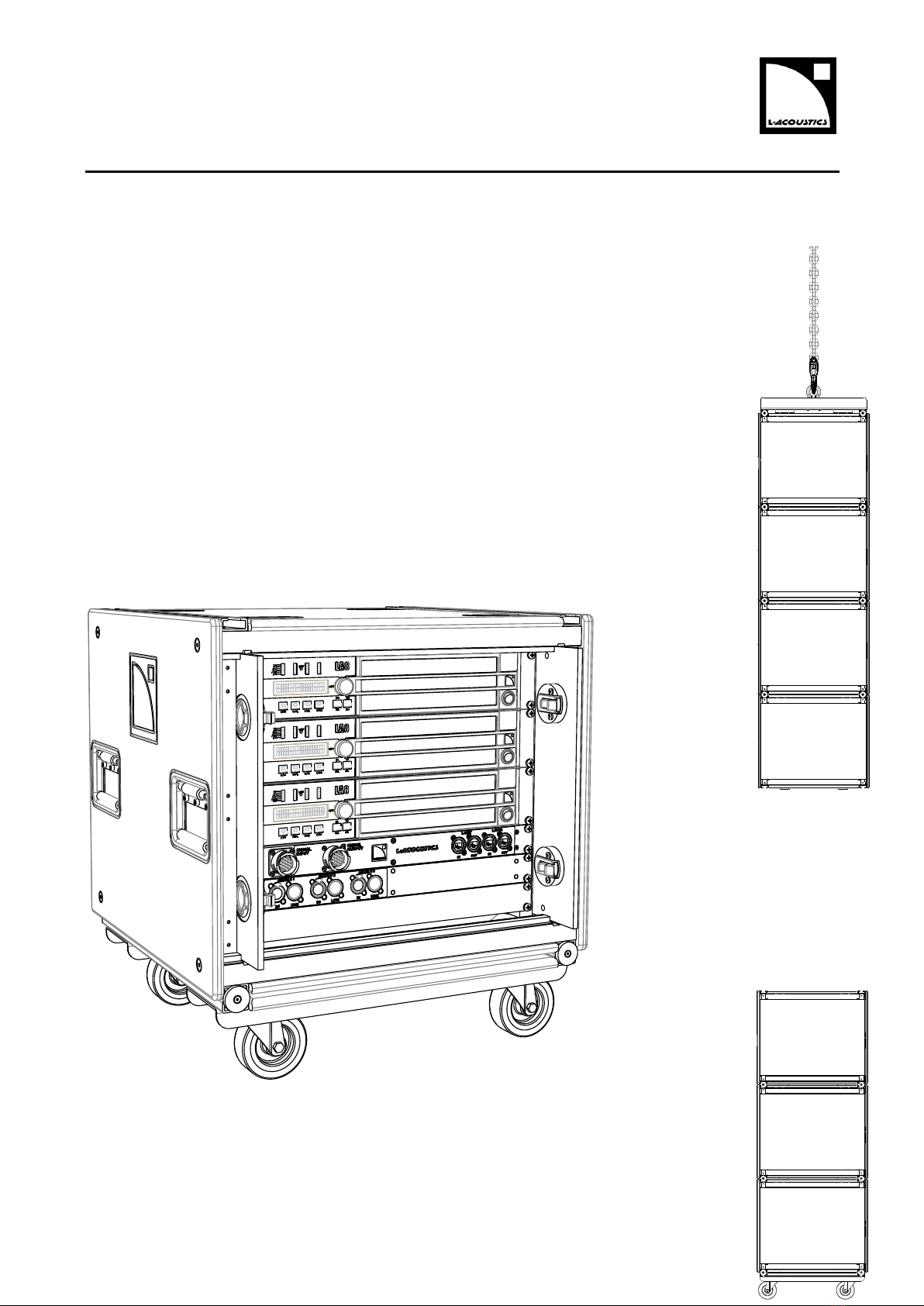
L-Acoustics LA-RAK User manual

LA-RAK
user manual

w w w . l - a c o u s t i c s . c o m
LA4 CONTROLEUR AMPLIFIE
Document Reference: LARAK_UM_EN_2.0
_________________
© Copyright 2017 by L-ACOUSTICS®
Parc de la Fontaine de Jouvence, 91462 Marcoussis cedex, France
_________________
Distribution date: February 23, 2017

LARAK_UM_EN_2.0 w w w . l - a c o u s t i c s . c o m 1
1SAFETY WARNINGS
All information hereafter detailed applies to the L-ACOUSTICS®LA-RAK Touring Rack, designated in this section
as the product. The LA-RAK product includes the following components: a RK 9U cabinet, three LA8 amplified
controllers and three distribution panels (LA-POWER, LA-PANEL and LA-PANEL AES3).
1.1 Symbol description
1.1.1 Symbols employed in this manual
Throughout this manual the potential risks are indicated by the following symbols:
The VOLTAGE symbol indicates a potential risk of electric shock that could be life threatening.
In addition, the product may also be seriously damaged.
The WARNING symbol indicates a potential risk of physical harm to the user or people within close
proximity to the product. In addition, the product may also be damaged.
The CAUTION symbol notifies the user about information to prevent possible product damage.
The IMPORTANT symbol is a notification of an important recommendation of use.
1.1.2 Symbols indicated on the product
As the product is an electrical device, it represents potential hazard for the user. For this reason the user may pay
particular attention to the symbols that are indicated on the covers of the product electrical components:
On the rear panel of the LA8 amplified controllers, the lightning flashes symbols
next to the 4-point SpeakON®and 8-point CA-COM®connectors indicate that
the product can deliver high output voltages that are potentially life threatening.
Connections between the product and a speaker should always be done with an
all ready-made lead. When the amplified controller is operating, never attempt to
touch any exposed speaker wire without disconnecting the connector first.
CAUTION
IMPORTANT
WARNING
VOLTAGE
!
CAUTION
RISK OF ELECTRIC SHOCK
DO NOT OPEN
WARNING:
RISK OF HAZARDOUS ENERGY
SEE OPERATING MANUAL
CLASS 2 PERMITTED

LA-RAK TOURING RACK
user manual
VERSION 2.0
LARAK_UM_EN_2.0 w w w . l - a c o u s t i c s . c o m 2
1.2 Important safety instructions
1. Read this manual
2. Heed all safety warnings
3. Follow all instructions
4. The user should never incorporate equipment or accessories not approved by L-ACOUSTICS®
5. Environments
Use the product only in E1, E2, E3, or E4 environments according to EN55103-2 standard.
6. Radio interference
A sample of this product has been tested and complies with the limits for the EMC (European Electro
Magnetic Compatibility) directive. These limits are designed to provide reasonable protection against
harmful interference from electrical equipment. However, there is no guarantee that interference will not
occur in a particular installation.
7. Power cord caution
Do not use the product if any power cord is broken or frayed.
Protect any power cord from being walked upon or pinched, particularly at the plugs and the points where
the power cords exit from the apparatus.
8. Mains supply
Only connect the product to an appropriate three-phase AC circuit and outlet. Consult an electrician if the
output voltage of the local AC mains is not known. Any electric device must be approved for the local
voltage & current rating. The specific electrical safety regulations of the country of use must be strictly
applied. Warranty will not cover damages caused by a mains wiring error.
9. Grounding
The product may only be connected to mains power supply tied to earth. If the local outlet is obsolete,
consult an electrician.
The LA-POWER is fitted with grounding-type sockets. Do not defeat the earth connections between the
sockets and the product chassis.
10. Lightning storms
During lightning storms, disconnect the product from mains.
Switching the amplified controllers off does not disconnect them from mains. Therefore, disconnecting can
only be achieved by removing the LA-POWER three-phase male plug from mains.
11. Interconnections
Before connecting the product to other equipment, turn the power off and unplug all of the equipment
from the supply source. Failure to do so may cause an electric shock and serious personal injury. Read the
user manual of the other equipment carefully and follow the manufacturer instructions.
Do not connect any amplified controller output to the output of another amplifier or to other voltage
source (such as a battery, mains source, or power supply), regardless of whether the product is turned on
or off.
12. Over power risks
The product is very powerful and can be potentially dangerous to both loudspeakers and humans alike.
Even when using the product’s front panel attenuator to reduce the gain, it is still possible to reach full
output power if the input signal level is high enough.
WARNING
VOLTAGE
VOLTAGE
VOLTAGE
VOLTAGE
VOLTAGE
IMPORTANT
IMPORTANT

LARAK_UM_EN_2.0 w w w . l - a c o u s t i c s . c o m 3
13. Ventilation
Openings in the LA8 amplified controller chassis are provided for ventilation. To prevent overheating and
ensure reliable operation, these openings must not be blocked or covered. The product should be installed
in accordance with the manufacturer instructions given in this manual.
14. Heat
Do not operate the product near any heat source, such as radiators or other devices.
15. Water and moisture
To prevent fire or shock hazard, do not expose the product to rain or moisture.
Do not use the product near water.
Do not operate the product while wet.
16. Interference with external objects and/or liquids
Never push objects of any kind into the product through openings as they may touch dangerous voltage
points or short out parts that could result in fire or electric shock. Never spill liquid of any kind on the
product.
17. Cleaning
Unplug the product from the mains power supply before cleaning.
Do not use liquid or aerosol cleaners.
Use only dry cloth when cleaning any electrical component.
18. Servicing and replacement parts
Do not attempt to service any product component as removing covers may expose to dangerous voltage or
other hazards.
All service and repair work must be carried out by an L-ACOUSTICS®authorized dealer.
The use of unauthorized replacement parts may result in injury and/or damage through fire, electric shock,
or other electricity-related hazards.
19. Conditions which require immediate service
Servicing is required when the product has been damaged in any way such as:
Any power supply cord or socket is damaged.
Liquid has been spilled or an object has fallen into any electrical component.
The product has been exposed to rain or moisture.
The product was dropped or the housing is damaged.
The product does not operate normally.
20. System parts and rigging inspection
All system components must be inspected before use in order to detect any possible defect.
Please refer to the “Care and Maintenance” section of this manual as well as any other manuals pertaining
to the system for a detailed description of the inspection procedure.
Any part showing any sign of defect must immediately be put aside and withdrawn from use to be
inspected by qualified service personnel.
21. Mounting instructions
Do not place the product on an unstable cart, stand, tripod, bracket, or table. The product may fall and be
seriously damaged, and may cause serious human injury. Mounting of the product should follow the
manufacturer instructions and should use the mounting accessories recommended by the manufacturer, as
described in this manual.
22. Personnel qualification
Installation of an assembly should only be carried out by qualified personnel that are familiar with the rigging
techniques and safety recommendations outlined in this manual. Any part showing any sign of defect must
immediately be put aside and withdrawn from use to be inspected by qualified service personnel.
WARNING
CAUTION
WARNING
CAUTION
VOLTAGE
CAUTION
VOLTAGE
VOLTAGE
CAUTION
CAUTION

LA-RAK TOURING RACK
user manual
VERSION 2.0
LARAK_UM_EN_2.0 w w w . l - a c o u s t i c s . c o m 4
23. Personnel health and safety
During installation of an assembly, personnel should wear protective headgear and footwear at all times.
Under no circumstances personnel should climb on the assembly.
24. Additional rigging equipment
L-ACOUSTICS®is not responsible for any rigging equipment and accessory that is not manufactured by L-
ACOUSTICS®.
It is the user’s responsibility to ensure that the Working Load Limit (WLL) of all additional hardware rigging
accessories is greater than the total weight of the rack assembly in use.
25. Suspension points
It is the user’s responsibility to ensure that the Working Load Limit (WLL) of the suspension points and/or
chain hoists is greater than the total weight of the assembly in use.
26. System load capacity and setup safety limits
Load capacity and setup safety limits outlined in this manual must never be exceeded.
27. Local regulations
Some countries require higher Ultimate Strength Safety Factors and specific rigging approvals. It is the user’s
responsibility to ensure that any overhead suspension of L-ACOUSTICS®systems has been made in
accordance with all applicable local regulations.
As a general rule, L-ACOUSTICS®recommends the use of safety steel at all times.
28. Flying an assembly
Always ensure that nobody is standing underneath an assembly when it is being raised.
As the assembly is being raised, check each individual rack to make sure that it is securely fastened to the
component above. Never leave the system unattended during the installation process.
29. Ground stacking an assembly
Do not ground stack an assembly on uneven ground or platform.
If the assembly is ground stacked on a structure, platform, or stage, always check that this last can support
the total weight of the system.
Secure the assembly to the structure, platform, or stage using ratchet straps or any other applicable device.
30. Dynamic load
When an assembly is deployed in an open air environment, wind effects should be taken into account. Wind
can produce dynamic stress to the rigging components and suspension points. If the wind force exceeds 6
bft (Beaufort scale) it is highly recommended to lower down and/or secure the assembly.
31. Manual
Keep this manual in a safe place during the product lifetime.
This manual forms an integral part of the product.
Reselling of the product is only possible if the user manual is available.
Any changes made to the product have to be written in this manual, particularly in the event of resale.
WARNING
WARNING
WARNING
WARNING
WARNING
WARNING
WARNING
WARNING
WARNING

LARAK_UM_EN_2.0 w w w . l - a c o u s t i c s . c o m 5
1.3 EC declaration of conformity
L-ACOUSTICS®
13 rue Levacher Cintrat
Parc de la Fontaine de Jouvence
91462 Marcoussis Cedex
France
States that the following products:
LA-RAK touring rack, composed of:
-Rack cabinet, RK 9U;
-Amplified controllers, LA8;
-Distribution panels, LA-POWER, LA-PANEL and LA-PANEL AES3.
LA-RAK BUMP flying frame.
Are in conformity with the provisions of:
98/37/EC: Machinery Directive;
73/23/EC: Low Voltage Directive;
89/336/EC: Electromagnetic Compatibility Directive.
Applied rules and standards:
EN ISO 12100-1: 2004: Safety of machinery;
DIN 18800: Steel Structures;
BGV-C1: Germany safety regulation for overhead rigging;
EN60065: Safety requirements for audio, video and similar electronic apparatus;
EN55103-1: Electromagnetic Interference (Emission);
EN55103-2: Electromagnetic Susceptibility (Immunity).
Established at Marcoussis, France
June 2nd, 2008
Christophe Pignon

LA-RAK TOURING RACK
user manual
VERSION 2.0
LARAK_UM_EN_2.0 w w w . l - a c o u s t i c s . c o m 6
2CONTENTS
1SAFETY WARNINGS 1
1.1 Symbol description .................................................................................................................................................. 1
1.2 Important safety instructions ................................................................................................................................... 2
1.3 EC declaration of conformity .................................................................................................................................. 5
2CONTENTS 6
3INTRODUCTION 7
3.1 Welcome to L-ACOUSTICS®.................................................................................................................................. 7
3.2 Unpacking................................................................................................................................................................ 7
3.3 Cross-references ..................................................................................................................................................... 8
3.4 Web links ................................................................................................................................................................. 8
4SYSTEM APPROACH BY L-ACOUSTICS®9
4.1 LA-RAK as a signal, network and power distribution system .................................................................................. 9
4.2 L-ACOUSTICS®components related to LA-RAK................................................................................................... 9
4.3 Supported configurations....................................................................................................................................... 11
5LA-RAK TOURING RACK 12
5.1 Global architecture ................................................................................................................................................ 12
5.2 RK 9U .................................................................................................................................................................... 13
5.3 LA8 amplified controllers....................................................................................................................................... 14
5.4 LA-POWER............................................................................................................................................................ 14
5.5 LA-PANEL ............................................................................................................................................................. 15
5.6 LA-PANEL AES3.................................................................................................................................................... 15
6INSTALLATION 16
6.1 Mounting components inside the LA-RAK............................................................................................................. 16
6.2 Moving and transporting the LA-RAK.................................................................................................................... 16
6.3 Amp cooling........................................................................................................................................................... 16
6.4 Rigging the LA-RAK ............................................................................................................................................... 18
6.5 Connecting LA-RAK to AC mains.......................................................................................................................... 25
6.6 Analog audio cabling .............................................................................................................................................. 27
6.7 Digital audio cabling............................................................................................................................................... 30
6.8 Loudspeaker cabling .............................................................................................................................................. 34
6.9 L-NET network cabling ......................................................................................................................................... 35
7CARE AND MAINTENANCE 38
7.1 Maintenance information....................................................................................................................................... 38
7.2 Checking procedures............................................................................................................................................. 38
7.3 Network cables replacement procedure .............................................................................................................. 39
7.4 Spare parts and recommended tools..................................................................................................................... 39
8SPECIFICATIONS 40
9APPENDIX: LA-POWER US 43
9.1 LA-RAK and LA-POWER US presentation ............................................................................................................ 43
9.2 Connecting LA-RAK US to AC mains .................................................................................................................... 43

LARAK_UM_EN_2.0 w w w . l - a c o u s t i c s . c o m 7
3INTRODUCTION
3.1 Welcome to L-ACOUSTICS®
Thank you for purchasing the L-ACOUSTICS®LA-RAK Touring Rack.
This manual contains essential information on installing and operating the product correctly and safely. Read this manual
carefully in order to become familiar with these procedures.
As part of a continuous evolution of techniques and standards, L-ACOUSTICS®reserves the right to
change the specifications of the product and the content of this manual without prior notice.
Should the product requires repair or if information about the warranty is needed, please contact an approved
L-ACOUSTICS®distributor. In order to obtain the address of the nearest distributor go to the L-ACOUSTICS®web
site.
3.2 Unpacking
Carefully open the shipping carton and check the product for any noticeable damage. Each L-ACOUSTICS® product is
tested and inspected before leaving the factory and should arrive in perfect condition.
If found to be damaged, notify the shipping company or the distributor immediately. Only the consignee may initiate a
claim with the carrier for damage incurred during shipping. Be sure to save the carton and packing materials for the
carrier's inspection.
The LA-RAK package consists of the following components (see from Figure 4 to Figure 7):
One L-ACOUSTICS®RK 9U cabinet with front and rear LEXAN® doors, one detachable dolly board and
two coupling bars.
Three L-ACOUSTICS®LA8 amplified controllers equipped with the LA-AES3 board.
One L-ACOUSTICS®LA-POWER.
One L-ACOUSTICS®LA-PANEL analog signal and network distribution panel, with eight XLR cables and
six CAT5e U/FTP cables.
One L-ACOUSTICS®LA-PANEL AES3 digital signal distribution panel.
The power distribution panel must be adapted to the mains rating of the country of use.
In Europe use the LA-POWER device (230 V version) presented all along this manual.
In USA use the LA-POWER US device (120 V version) presented in Appendix.
In any other country contact a local L-ACOUSTICS®distributor.
The optional LA-RAK BUMP package consists of the following components (see Figure 13):
One L-ACOUSTICS®LA-RAK BUMP flying frame.
Two ⅝” shackles.
IMPORTANT

LA-RAK TOURING RACK
user manual
VERSION 2.0
LARAK_UM_EN_2.0 w w w . l - a c o u s t i c s . c o m 8
3.3 Cross-references
All along the manual, a bracketed number refers to a section. For example, [3.3] stands for the present section: Cross-
references.
3.4 Web links
Please check the L-ACOUSTICS®web site on a regular basis for latest document and software application updates.
Table 1 provides links for all downloadable items mentioned in this manual.
ALWAYS refer to the latest document version.
ALWAYS use the latest software application version.
Table 1: Links to documents and software applications
Generic path for all products
www.l-acoustics.com/ +product name
LA8 User manual
LA8 FIRMWARE Pack
LA8 PRESET LIBRARY Pack
www.l-acoustics.com/la8
LA-RAK User manual
LA-RAK Spec sheets
www.l-acoustics.com/la-rak
LA8 PACOM CABLES Technical bulletin
www.l-acoustics.com/download (Technical publications)
LA NETWORK MANAGER User manual
www.l-acoustics.com/la-network-manager
IMPORTANT

LARAK_UM_EN_2.0 w w w . l - a c o u s t i c s . c o m 9
4SYSTEM APPROACH BY L-ACOUSTICS®
4.1 LA-RAK as a signal, network and power distribution system
The L-ACOUSTICS®LA-RAK Touring Rack is a central element of the L-ACOUSTICS®system architecture built
upon the LA8 amplified controller. It offers an advanced rack solution for all L-ACOUSTICS®systems covering signal,
power and network distribution in a comprehensive plug and play touring package. LA-RAK was created as a universal
platform designed to facilitate cross-rental and to ensure compatibility with the legacy cabling standard of L-
ACOUSTICS®systems.
4.2 L-ACOUSTICS®components related to LA-RAK
The system approach developed by L-ACOUSTICS®consists in providing all the components needed to offer the
highest, most predictable level of performance. Here are the main components that can be used when setting an L-
ACOUSTICS®system with LA-RAK (see Figure 1):
8XT, 8XTi, 12XT, 12XTi, 115XT HiQ
2-way coaxial enclosures
KIVA, KARA®, KARAi®, dV-DOSC, ARCS®
2-way WST®enclosures
K1, KUDO®, V-DOSC®
3-way WST®enclosures
K1-SB, dV-SUB
Subwoofer extensions for K1 and dV-DOSC, respectively
SB18, SB18i, SB28
Subwoofer enclosures
LA NETWORK MANAGER
Remote control software
SOUNDVISION
Acoustical and mechanical 3D modeling software
A complete L-ACOUSTICS®system also features standard L-ACOUSTICS®cables and rigging accessories. For more
details refer to the appropriate manuals [3.4].

LA-RAK TOURING RACK
user manual
VERSION 2.0
LARAK_UM_EN_2.0 w w w . l - a c o u s t i c s . c o m 10
Figure 1: Main system components related to the LA-RAK
LA NETWORK MANAGER
SOUNDVISION
LA-RAK
V-DOSC
KUDO
K1
K1-SB
ARCS
SB18
SB28
dV-SUB
SB18i
dV-DOSC
KARA
KARAi
115XT HiQ
12XT
12XTi
8XT
8XTi
KIVA
KILO

LARAK_UM_EN_2.0 w w w . l - a c o u s t i c s . c o m 11
4.3 Supported configurations
The LA-RAK working principle is entirely modular, so that the engineer can physically assemble and interconnect
multiple elements to fit numerous applications. The LA-RAK configuration based on a multiple of 3 LA8 yields the
maximum flexibility and power resources for any L-ACOUSTICS®system, from compact coaxial systems up to KUDO®
and K1 stadium line source array systems. Some examples are illustrated in Figure 2:
Figure 2: Power capacity and flexibility of the LA-RAK
LA-RAK power capacity (each of the represented systems can be driven by one LA-RAK)
LA-RAK flexibility (split 2/3-1/3, two LA8 driving a main system, one LA8 driving sub companions)

LA-RAK TOURING RACK
user manual
VERSION 2.0
LARAK_UM_EN_2.0 w w w . l - a c o u s t i c s . c o m 12
5LA-RAK TOURING RACK
5.1 Global architecture
The L-ACOUSTICS®LA-RAK is a 9U rack cabinet in which are mounted three LA8 amplified controllers, as well as
three distribution panels: LA-POWER for power, LA-PANEL for analog signals and network, and LA-PANEL AES3 for
digital audio signals.
Figure 3: Equipped LA-RAK
Front
Rear

LARAK_UM_EN_2.0 w w w . l - a c o u s t i c s . c o m 13
5.2 RK 9U
The L-ACOUSTICS®RK 9U cabinet is a dual structure consisting of a rubber shock inner steel frame braced by an
external aluminum frame sided with highly resistant polyethylene panels. This ensures structural integrity while offering
decoupling and maximum protection of the electronics inside the rack. Two retractable LEXAN®doors protect the
internal components during transport.
On the front face, one extra U space can be fitted with a shelf to receive an additional switch, for L-NET network star
topologies for instance.
On the rear face, two hinge-mounted panels cover and protect the analog, digital and network connectors of the
amplified controllers to create a neat and tangle-free cable environment. The rear central part of the amplified
controllers remains accessible with its CA-COM®and SpeakON®sockets.
The RK 9U is equipped in standard with a detachable transport dolly board and two coupling bars. These last also allow
arraying several LA-RAK in flown or stacked configurations.
Figure 4: The RK 9U cabinet
Hinge-mounted panel (x2)
Polyethylene
panel
Steel frame
Retractable door storage slot (x2)
Rubber shock mount (x8)
Dolly board
Coupling bar (x2)
Aluminum frame

LA-RAK TOURING RACK
user manual
VERSION 2.0
LARAK_UM_EN_2.0 w w w . l - a c o u s t i c s . c o m 14
5.3 LA8 amplified controllers
The L-ACOUSTICS®LA8 amplified controller is the top of the range of high-end integrated controllers entirely
dedicated to the comprehensive operation of L-ACOUSTICS®loudspeaker systems. In a 2U lightweight chassis, the
LA8 combines the resources of a 2 x 4 DSP engine driving four channels of amplification and delivering up to 1800 W
per channel at 4 ohms. It features a storage capacity of 99 presets, a user-friendly front panel interface, two I/O
Ethernet®connection ports for network remote control, a connection panel for analog audio inputs, an LA-AES3 board
for digital audio inputs and a connection panel for speaker outputs. Refer to LA8 User manual [3.4] for more details.
Figure 5: The LA8 amplified controller
5.4 LA-POWER
The L-ACOUSTICS®LA-POWER is a 2U/19” I/O 230 V power distribution panel featuring a 32 A three-phase
circuit: one IN plug and one LINK OUT outlet to power a secondary rack. This configuration allows the power to be
automatically balanced with an even number of LA8 per phase.
Three “Shuko” AC outlets (L1, L2, and L3) are available for LA8, and three additional outlets (1 x “Shuko” and 2 x IEC)
are available to power auxiliary accessories such as Ethernet®switches, portable computer, and the like. All circuits are
protected by discrete circuit breakers and three LED help monitor phase presence.
Note: The three LA8 AC outlets can be replaced by a 3 x 20 A Powercon®plate using the predrilled template fitted
with four M5 screws (the “M5” notation refers to the European standard, see applicable external documentation).
Note: See Appendix 0 for LA-POWER US description or contact a local L-ACOUSTICS®representative for any
country located outside Europe and USA.
Figure 6: The LA-POWER
L1, L2, L3, and Aux. circuit breakers
L1, L2, and L3 “Shuko” outlets
Auxiliary IEC outlets
L1, L2, and L3 phase presence LED
M5 insert (x4)
Auxiliary “Shuko” outlet
IN plug
LINK OUT outlet

LARAK_UM_EN_2.0 w w w . l - a c o u s t i c s . c o m 15
5.5 LA-PANEL
The L-ACOUSTICS®LA-PANEL allows distribution of 6 analog audio signals. The LA-RAK is fed with the signals
through the SIGNAL INPUT 19-point PA-COM®connector. The signals can be distributed to the 3 amplifiers thanks to
6 OUT XLR3 connectors on the rear side of the panel. The SIGNAL OUTPUT 19-point PA-COM®connector allows
sending the 6 signals to another LA-RAK in a daisy-chain layout. The PA-COM®connectors ensure compatibility with
the L-ACOUSTICS®cabling standard (DOM2, DOM30, DOMF, and DOMM cables).
The panel also features 4 Ethercon®I/O sockets for L-NET control & monitoring network and L-DGA digital audio
network (for future applications).
Figure 7: The LA-PANEL
5.6 LA-PANEL AES3
The L-ACOUSTICS®LA-PANEL AES3 allows distribution of 6 digital audio signals. The LA-RAK is fed with AES/EBU
signals through 3 IN XLR3 connectors, each of them receiving 1 digital signal conveying 2 audio channels. The signals
can be distributed to the 3 amplifiers thanks to 3 OUT XLR3 cables integrated on the rear side of the panel. In order to
set a daisy-chain layout, the 3 LINK XLR3 cables allow routing pairs of channels from the LINK connector of the
amplifiers to the corresponding LINK XLR3 connector on the front side of the LA-PANEL AES3.
Also are provided 2 extra XLR cables, to connect LINK and IN connectors on the front of the panel. This operation
allows setting a daisy-chain between controllers within the LA-RAK (see [6.7]).
Figure 8: The LA-PANEL AES3
FRONT
REAR
XLR3 connectors
(for external AES/EBU digital audio cabling)
XLR3 cables
(for internal AES/EBU digital audio cabling)
19-point PA-COM®connectors
(for external analog audio cabling)
Ethercon®sockets
(for external network cabling)
RJ45 sockets
(for internal network cabling)
XLR3 connectors
(for internal analog audio cabling)
Strain relief protection plate for network I/O
Internal network cable (x4)

LA-RAK TOURING RACK
user manual
VERSION 2.0
LARAK_UM_EN_2.0 w w w . l - a c o u s t i c s . c o m 16
6INSTALLATION
6.1 Mounting components inside the LA-RAK
The 9U inner frame (see Figure 4) is for mounting components to both front and rear faces:
The LA-PANEL, the LA-PANEL AES3 and optional switches mount to the front face using four screws and
four washers each.
The LA-POWER mounts to the rear face using four screws and four washers.
Each LA8 mounts to both front and rear faces using eight screws and eight washers.
During transport or while on tour it is essential that the LA8 controllers are rear supported in addition to
the front panel mounting. Use the rear rack support brackets provided with each LA8 or the LA-RAK
optional spacers (see references in section [7.4]).
6.2 Moving and transporting the LA-RAK
The removable dolly board (see Figure 10) is for moving and transporting a vertical array of two LA-RAK. It secures
to the bottom LA-RAK using two coupling bars (see [6.4]).
For moving or transporting purposes, a maximum of two LA-RAK can be set onto one dolly board.
6.3 Amp cooling
Each LA8 amplified controller uses a forced air cooling system to maintain a low and even operating temperature. All
fan cooled L-ACOUSTICS®amplified controllers have front to rear airflow.
Before operation, ensure that the front filter system of each LA8 is clean and dust free (see the LA8 User
Manual [3.4]).
While operating keep the LEXAN®front and rear doors retracted (see below) and do not block the LA8
front and rear air vents.
CAUTION
CAUTION
WARNING

LARAK_UM_EN_2.0 w w w . l - a c o u s t i c s . c o m 17
Apply the following procedure to retract and lock the LEXAN®doors:
a. Detach both doors and slide them along both LA-RAK sides (between the outer aluminum frame and the
inner steel frame).
b. Insert and lock both ball locking pins through each door’s bottom hole.
Figure 9: Retracting and locking both LEXAN®doors
Outer aluminum frame
Inner steel frame
LEXAN®doors
Ball locking pin (x2)
a.
b.

LA-RAK TOURING RACK
user manual
VERSION 2.0
LARAK_UM_EN_2.0 w w w . l - a c o u s t i c s . c o m 18
6.4 Rigging the LA-RAK
The LA-RAK features four fully integrated rigging rails on top and bottom faces as well as four stacking runners which
mate with four runner guides. These are for assembling several LA-RAK in stacked or flown configurations such as:
Stacking a vertical array of up to 3 LA-RAK onto one dolly board;
Flying a vertical array of up to 4 LA-RAK underneath the L-ACOUSTICS®LA-RAK BUMP flying frame
or onto the L-ACOUSTICS®K1-BUMP flying frame.
6.4.1 Stacking procedure
All along the procedure:
Strictly follow the sequence of the successive steps.
Systematically ensure that each spring-loaded safety is in locking position.
1. Bring a first LA-RAK at the stacking location.
2. Bring a second LA-RAK and remove its dolly board:
a. Turn a spring-loaded safety and slide out the coupling bar.
b. Repeat for the second coupling bar.
Figure 10: Removing the dolly board from the LA-RAK
3. Lift up the second LA-RAK and install it on the first one: align the rails and set the stacking runners into the runner
guides.
WARNING
a.
a.
b.
b.
Other manuals for LA-RAK
1
Table of contents
Other L-Acoustics Amplifier manuals

L-Acoustics
L-Acoustics LA4 User manual

L-Acoustics
L-Acoustics LA15a User manual

L-Acoustics
L-Acoustics LA 24 User manual

L-Acoustics
L-Acoustics LA24a User manual

L-Acoustics
L-Acoustics LA4X User manual

L-Acoustics
L-Acoustics LA12X User manual

L-Acoustics
L-Acoustics V-DOSC User manual

L-Acoustics
L-Acoustics LA48A User manual

L-Acoustics
L-Acoustics LA8 User manual