Becen BC-M230 User manual

www.szbecen.com
USER’S MANUAL
Model: BC-M230
230w Beam Moving Head Light (White)
Package Includes:
1 x beam moving head light
1 x clamp,handle
1 x safe cable
1 x power cable
1 x DMX cable
Please read this manual before use

www.szbecen.com
CONTENTS
Chapter 1 Warnings and Operation Modes.................................................................................... 1
1.1 Warnings.......................................................................................................................... 1
1.2 Operation Modes........................................................................................................... 1
Chapter 2 Control Panel Instructions............................................................................................. 2
2.1 Main Interface.................................................................................................................. 2
2.2 Setting of Interface .......................................................................................................... 3
2.3 Information Interface....................................................................................................... 3
2.4 Information Interface....................................................................................................... 4
2.5 Advanced Interface.......................................................................................................... 4
Chapter 3 Channel description....................................................................................................... 5
3.1 Channel table................................................................................................................... 5
3.2 Channel Detail................................................................................................................. 5
3.2.1 COLOR WHEEL-channel 1.................................................................................... 5
3.2.2 STOP/STOBE-channel 2 ......................................................................................... 7
3.2.3 DIMMER-channel 3................................................................................................ 7
3.2.4 STATIC GOBO CHANGE-channel 4...................................................................... 7
3.2.5 PRISM INSERTION-channel 5............................................................................... 9
3.2.6 PRISM ROTATION-channel 6................................................................................ 9
3.2.7 PRISM ROTATION-channel 6................................................................................ 9
3.2.8 PRISM ROTATION-channel 6................................................................................ 9
3.2.9 FOCUS-channel 9.................................................................................................... 9
3.2.10 PAN-channel 10..................................................................................................... 9
3.2.11 PAN FINE-channel 11 ........................................................................................... 9
3.2.12 TILI-channel 12................................................................................................... 10
3.2.13 TILT FINE-channel 13......................................................................................... 10
3.2.14 FUNCTION-channel 14(NOUSED).................................................................... 10
3.2.15 RESET-channel 15............................................................................................... 10
3.2.16 LAMP CONTROL-channel 16............................................................................ 10
3.2.17 TIMING CHANNELS......................................................................................... 10
Chapter 4 Control signal connection ........................................................................................... 10
Chapter 5 Installation................................................................................................................... 12
Chapter 6 Protection and Maintenance........................................................................................ 18
6.1 Light cleaning................................................................................................................ 18
6.2 Statement ....................................................................................................................... 19
6.3 Problem solve method ................................................................................................... 19

1
www.szbecen.com
Chapter 1 Warnings and Operation Modes
1.1 Warnings:
Please check if there is any transportation damage before using. And if there is any
damage, please stop using it, and contact the distributor or manufacturer as soon as
possible. Please keep it away from Combustible materials, and unlock the X-, Y-axis
before using. The fixture should be installed in places with good ventilation, keep it
away from the wall at least 10cm above, and then check if the fans are in good
conditions.
Please don’t project the light beam on the combustible directly, and keep the fixture at
least 12m away from the projection objects.
Please don’t look directly into the light source lest any damage to your eyes. And
please make sure the using power voltage is in accordance with the stated voltages
before using.
Attention: Please power off before installing, repairing or cleaning
the fixture.
1.2 Operation Modes
For example, how to change DMX address?
Please press “Setting” in the main interface to enter “setting” interface.
There are 4 touch key-presses on the right side, namely, “Up” “Confirm” “Down”
“Return” buttons.
Please press “Up” or “Down” keys to enter “DMX address”.
Please press “Confirm” to edit.
Please press “Up” or “Down” keys to change DMX address(the new DMX
address would be saved automatically and start to run)
Please press “Confirm” to exit editing.
Please press “Return” to exit main manual.
Operation modes for turning wheel:
Please press “Setting”button under the main interface, and turn the wheel.
Touch
Turning Wheel
Function
“Up”button
Turn left
Select、Edit
“Down”button
Turn right
Select、Edit
“Confirm”button(“OK”)
Press the wheel
Start running
Start editing、Stop editing
“Return”button
Press the wheel under
Return manual
Return to previous page
2
www.szbecen.com
Please press the wheel to enter “setting”interface.
Please turn the wheel to enter “DMX address”interface under “setting”interface.
Please press the wheel to edit.
Please turn the wheel to change the DMX address.
Please press the wheel to exit editing after the modification.
Please turn the wheel to enter “Return”, and then press the wheel to return the
main interface.
Chapter 2 Control Panel Instructions
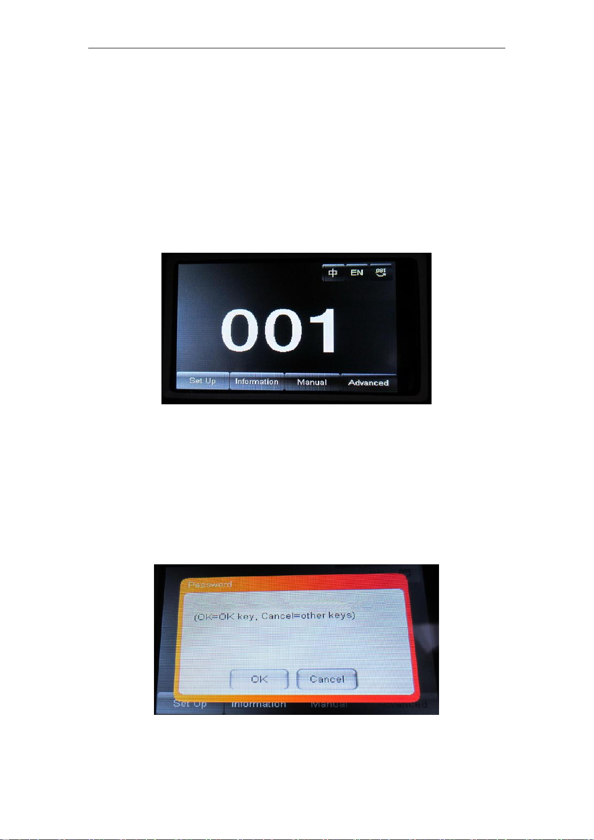
2.1. Main Interface
The 3 buttons on the up right corner are for language switch and screen rotation.
The 4 buttons on the bottom are for sub-interfaces.
How to use the wheel to control the sub-interface? Please see as follows::
For “Up”button: Please turn left.
For “Down”button: Please turn right.
For “Confirm”button: Please press the wheel.
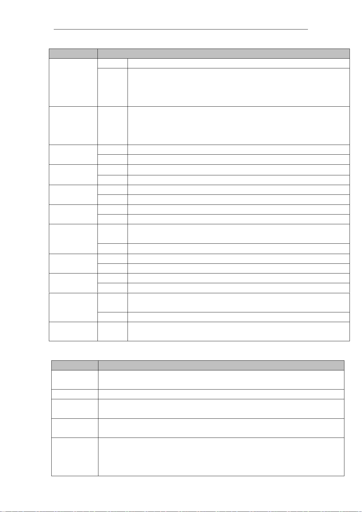
Operation of Dialog by turning wheel:
If for “YES”, then press the wheel. And if for “No”, then turn the wheel.
3
www.szbecen.com
2.2. Setting of Interface
Options
Instructions
Running
Mode
DMX
Slave machines:accept DMX signals from controller or Master machine.
Auto
Master-Slave:running automatically, and send DMX signals to slave
machines.
Attention:If need to check the light effects, please power on the lamp
first to enter self-propelled state.
DMX
Address
1-512
Press “Confirm” button to edit. First is for “hundred's digit”, and press
“Up” and “Down” to change the address codes. Press “Confirm” button
the second time to edit “ten's digit”, and press again the “Confirm”
button to edit “unit's digit”. Please press it again to exit editing.
Channels
16
17-20 CH Invalid
20
17-20CH to control speed(please refer to Channel chart)
X Reverse
off
on
Y Reverse
off
on
XY Exchange
off
on
Exchanging XY channels(Pan/Tilt fine included)
XY Encorder
on
Use Encorder (optocoupler) to judge out of sync or not, and self-correct
the position.
off
Don’t use Encorder (optocoupler) to rectify the position
No DMX
signal
stay
Stay the same
reset
Stop running
Screen Save
mode
on
Screen light off automatically after 30secs
off
Screen stay on
Starting up
off
Reset directly when power on,lamp stay off(need to operate the manu or
console to light up the lamp)
on
Lamp on when power on,and reset after the lamp is fully lighted up.
Recover
default setting
Press “Confirm” button to see the confirm dialog, and press “Confirm”
button again to recover default setting.
2.3.Information Interface
Options
Illustrate
Software
version
The current software version
Total time
Total time (accurate to the minute)
The use of
time
Since the boot (accurate to the minute)
DMX
Channel
Click here to go to the sub-interface, numerical and percentage display channel
for viewing.
System error
records
If the red ERR indicator light, illustrate lamps run error, Details Click here go to
the sub-interface view. After you finish, press "OK" key to delete error records.
Note: sometimes it is not Hall or optocoupler installation problems, but the motor
line reversed.
4
www.szbecen.com
2.4. Manual Control Interface
This interface is used to control the current lighting, neither belong to slave state (does
not receive DMX signal), nor belong to the host state (do not send DMX signal)
Options
Illustrate
Reset
Press the OK button after see a confirmation dialog box, click "OK" key
to enter the reset interface, all motor reset again.
Color
Wheel
0-255
Press “Confirm” button to edit. First is for “hundred's digit”, and press
“Up” and “Down” to change the address codes. Press “Confirm” button
the second time to edit “ten's digit”, and press again the “Confirm” button
to edit “unit's digit”. Please press it again to exit editing.
。。。。。。
0-255
Gobo
Wheel
Speed
0-255
Bulb
Control
Turn
on
Turn
off
2.5. Advanced Interface
The code is “up down up down”,and code for the wheel is “ left right left right”.
Manu Operation modes:Press “Up” to see the first “*”,and press “Down” key to see
the second “*”,and press “Up” to see the third “*”,and press “Down” key to see the
fourth “*”,and last press “Confirm” key to enter password confirmation.
Turning wheel Operation modes:Turn one bit left to see first “*”, and Turn one bit
right to see the second “*”,and turn one bit left to see the third “*”, and Turn one bit
right to see the fourth “*”,and last press the wheel to enter password confirmation.
Options
Instructions
Touch Screen
Calibration
Please touch the place according to the prompt of the cross cursor in the
Calibration interface. If the 4 values received the right data, then save
the data. If failed, it will keep repeating. Please press “Confirm”
button to stop Calibration any time.
Reset Calibration
When enter sub-menu, the reset location of X.Y axis motors is
adjustable. It is not able to edit “unit’s digit”, “ten's digit” or
“hundred's digit” or long-time press for Reset Calibration which
needs to be calibrated step by step, which is different from address code
and channel values.
Attention:Please don’t conduct Reset Calibration, when the motors are
working.
And please reset the fixture before Reset Calibration when necessary.
5
www.szbecen.com
Chapter 3 Channel Description
3.1 Channel Table
CHANNEL
CHANNEL MODE
16
20
1
COLOUR WHEEL
COLOUR WHEEL
2
STOP/STROBE
STOP/STROBE
3
DIMMER
DIMMER
4
STATIC GOBO CHANGE
STATIC GOBO CHANGE
5
PRISM ROTATION
PRISM ROTATION
6
PRISM ROTATION
PRISM ROTATION
7
EFFECTS
MOVEMENT(UNUSED)
EFFECTS MOVEMENT(UNUSED)
8
FROST
FROST
9
FOCUS
FOCUS
10
PAN
PAN
11
PAN FINE
PAN FINE
12
TILT
TILT
13
TILT FINE
TILT FINE
14
FUNCTION(UNUSED)
FUNCTTON(UNUSED)
15
RESET
RESET
16
LAMP CONTROL
LAMP CONTROL
17
PAN-TILT TIME
18
COLOUR TIME
19
DIMMER-PRISM-FROST TIME
20
GOBO TIME
3.2 Channel Detail
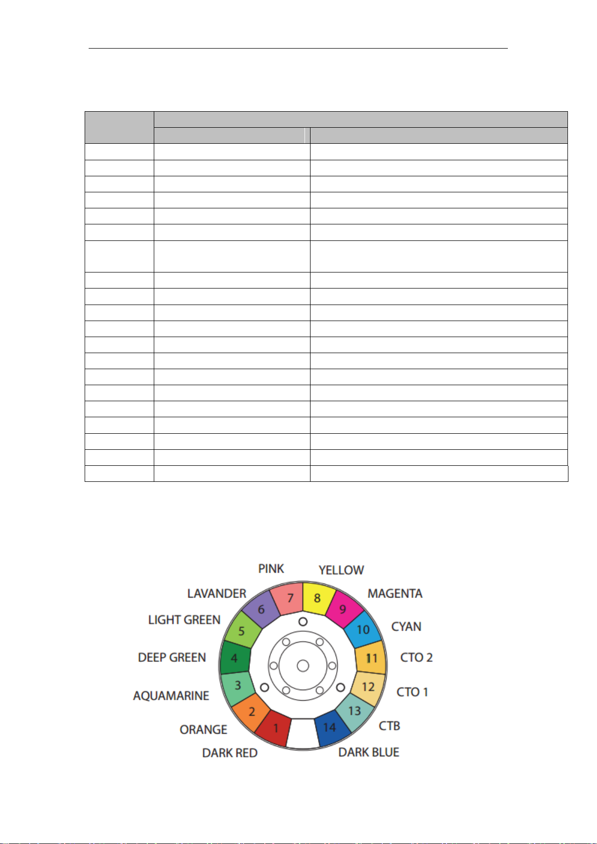
3.2.1 COLOR WHEEL-channel 1

6
www.szbecen.com
BIT
EFFECT
备注
255
FAST ROTATION
......
……
150
SLOW ROTATION
145
COOL COLOR +WHITE
In order to facilitate
memory, color value is
always a multiple of five.
Color ratio can be adjusted,
for example: when the
value is five, so it should
be 50% white, dark red
50%, if the value is 4, so it
should be 60% white, dark
red 40%: If the value is six,
so it should white 40%
dark, red 60%.
140
COOL COLOR
135
BROWNISH YELLOW+COOL COLOR
130
BROWNISH YELLOW
125
LIGHT BLUE-PURPK+BROWNISH YELLOW
120
LIGHT BLUE-PURPK
115
MAGENTA+LIGHT BLUE-PURPK
110
MAGENTA
105
YELLOW GREEN+MAGENTA
100
YELLOW GREEN
95
LIGHT YELLOW+YELLOW GREEN
90
LIGHT YELLOW
85
BLUISH GREEN+LIGHT YELLOW
80
BLUISH GREEN
75
PURPLISH RED+BLUISH GREEN
70
PURPLISH RED
7
www.szbecen.com
65
FLUORESCENCE+PURPLISH RED
60
FLUORESCENCE
55
BROWN+FLUORESCENCE
50
BROWN
45
GREEN+BROWN
40
GREEN
35
BLUE+GREEN
30
BLUE
25
DARK YELLOW +BLUE
20
DARK YELLOW
15
RED+DARK YELLOW
10
RED
5
WEITE+RED
0
WEITE
3.2.2 STOP/STOBE-channel 2
BIT
EFFECT
Remarks
252-255
OPEN
Controlled by a dimmer channel
239-251
RANDOM FAST STROBE
226-238
RANDOM MEDIUM STROBE
213-225
RANDOM SLOW STROBE
208-212
OPEN
Controlled by a dimmer channel
207
FAST PULSATION
……
……
108
SLOW PULSATION
104-107
OPEN
Controlled by a dimmer channel
103
FAST STROBE
……
……
4
SLOW STROBE
0-3
CLOSED
3.2.3 DIMMER-channel 3
BIT
EFFECT
Remarks
255
100%
……
……
0
0%
3.2.4 STATIC GOBO CHANGE-channel 4

8
www.szbecen.com
BIT
EFFECT
Remarks
255
GOBOI 17 SHAKE,FAST SPEED
Every five values is correspond to a
pattern.
……
……
251
GOBO 17 SHAKE,SLOW SPEED
250
GOBO 16 SHAKE,FAST SPEED
……
……
246
GOBO 16 SHAKE,SLOW SPEED
……
……
180
GOBO 2 SHAKE,FAST SPEED
……
……
176
GOBO 2 SHAKE,SLOW SPEED
175
GOBO 1 SHAKE,FAST SPEED
……
……
171
GOBO 1SHAKE,SLOW SPEED
170
FAST ROTATION
……
……
135
SLOW ROTATION
130-134
STOP
129
SLOW ROTATION
……
……
90
FAST ROTATION
85
GOBO 17
Value is always five multiple
80
GOBO 16
75
GOBO 15
70
GOBO 14
65
GOBO 13
60
GOBO 12
55
GOBO 11
50
GOBO 10
45
GOBO 9
40
GOBO 8
35
GOBO 7
9
www.szbecen.com
30
GOBO 6
25
GOBO 5
20
GOBO 4
15
GOBO 3
10
GOBO 2
5
GOBO 1
0
WHITE
3.2.5 PRISM INSERTION-channel 5
BIT
EFFECT
Remarks
128-255
PRISM INSERTED
0-127
PRISM EXCLUDED
3.2.6 PRISM ROTATION-channel 6
BIT
EFFECT
Remarks
255
FAST ROTATION
……
……
193
SLOW ROTATION
191-192
STOP
190
SLOW ROTATION
……
……
128
FAST ROTATION
0-127
POSITION
3.2.7 EFFECTS MOVEMENT channel 7(NOUSED)
3.2.8 FROST-channel 8
BIT
EFFECT
Remarks
128-255
FROST INSERTED
0-127
FROST EXCLUDED
3.2.9 FOCUS-channel 9
BIT
EFFECT
Remarks
255
100%
……
……
0
0%
3.2.10 PAN-channel 10
(………)
3.2.11 PAN FINE-channel 11
(………)
10
www.szbecen.com
3.2.12 TILI-channel 12
(………)
3.2.13 TILT FINE-channel 13
(………)
3.2.14 FUNCTION-channel 14(NOUSED)
3.2.15 RESET-channel 15
BIT
EFFECT
Remarks
128-255
COMPLETE RESET
Reset is activated passing through the unused range
and staying 5 seconds.
77-127
PAN/TILT RESET
26-76
EFFECTS RESET
0-25
UNUSED RANGE
3.2.16 LAMP CONTROL-channel 16
BIT
EFFECT
Remarks
128-25
5
LAMP ON
Lamp switch passing through the unused range and staying 5
seconds.
10-100
LAMP OFF
0-9
UNUSED RANGE
3.2.17 TIMING CHANNELS
Timing Channel
Channel function
Remark
17
Pan-Tilt time
Pan-Tilt-(Pan fine-Tilt
fine)
255 SLOW SPEED
….. ……
0 FAST SPEED
18
Color time
Color wheel
19
Beam time
Dimmer-Prism-Frost
20
Gobo time
Static Gobo
Chapter 4 Control signal connection
XLR-XLR control cable from the DMX output of the controller connected to
each projector DMX input port, and from the first fixture in the DMX output port
connected to the second fixture in the DMX input port, and so on, until the All
lighting connection is completed, and then plug the supplied loop connected to the
signal output of the last fixture to complete the connection, as shown:

11
www.szbecen.com
Note: Keep in mind that in the last fixture's output circuit connected to a plug, this
circuit is connected to a 120 ohm resistor inserted between the CANON (XLR) plug 2
feet and 3 feet, this loopinterpolation can effectively avoid the reflection signal
generated by DMX512 signal in transfer input process.
The moving head light utilization the 3-pin XLR socket (head),if you are using the
controller uses a 5-pin XLR socket (head), you must use a 5-pin to 3-pin converter
cable, as shown below:
3-pin and 5-pin control cable plug (male and female) connector.
Three pin(Canon)DMX512 connector

12
www.szbecen.com
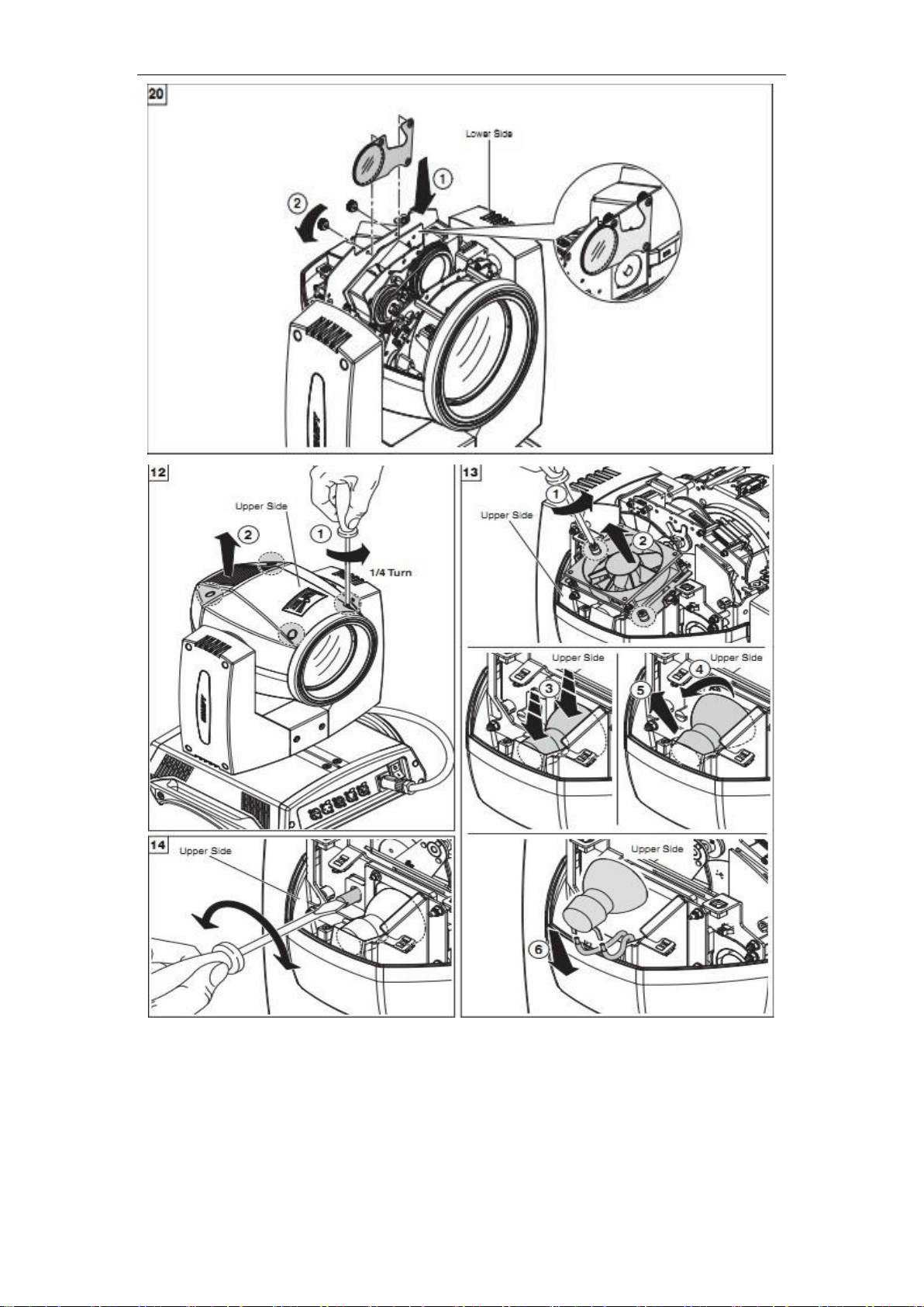
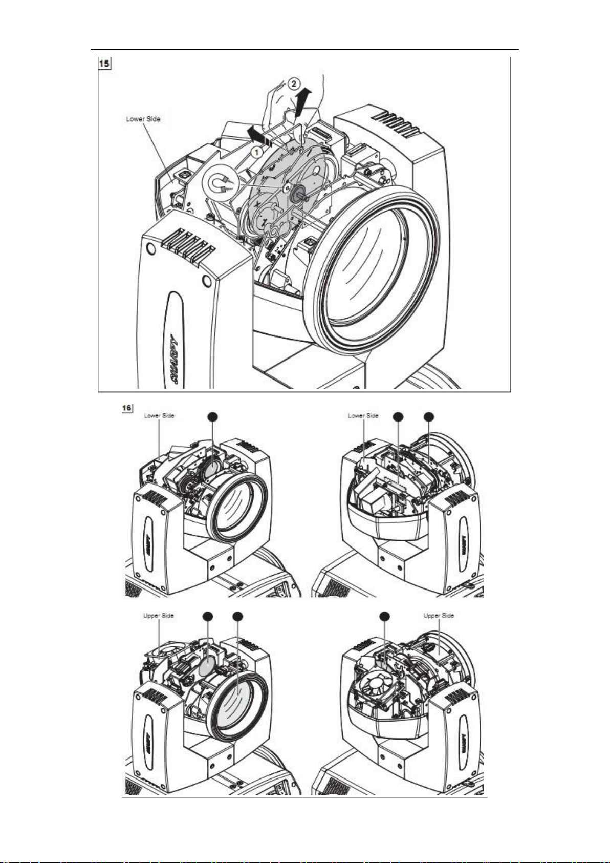
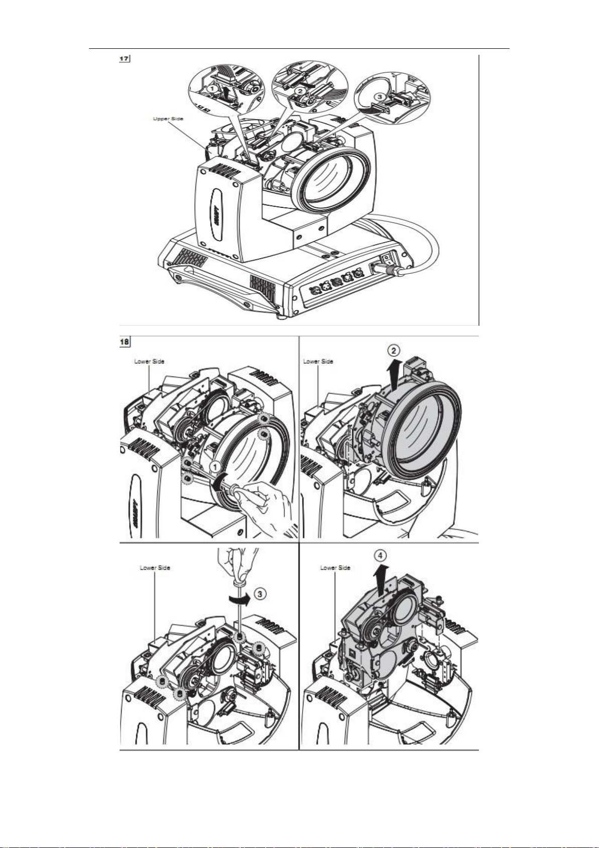
Chapter 5 Installation

13
www.szbecen.com

14
www.szbecen.com
15
www.szbecen.com
16
www.szbecen.com
17
www.szbecen.com

18
www.szbecen.com
Chapter 6 Protection and Maintenance
You should exchange the lens timely, if you find the led has damaged. You
should instant replacement the bulb when you find the deformation damage. The
aging bulb has a danger of blowout. Please check the power fuse of light when the
light unable to start. Install the corresponding specification fuse 6.35X32 T15A/250V
when burning. Light has overheating protection device, Protection device will
automatically cut off power supply when overheating. Please check the fan’s
operation, dirt jam between fan and fan nets when the situation happened. Find the
reason and repair then restarting light. Attention only qualified technical personnel
can repair it.
6.1 Light cleaning
It is necessary to keep the light cleaning to ensure its reliable use. The fan should
clean every 15 days. It needed to clean periodically of the internal and external optical
lens, mirror and coating color filter in order to optimize the efficacy output. Do not
use any chemical solvents containing to clean color filter. The frequency of cleaning
is according to the operation of light and the environment of operation.
Table of contents
Popular Floodlight manuals by other brands


Lithonia Lighting
Lithonia Lighting HGX LED 2RH ALO SWW2 120 PIR installation instructions

Chauvet
Chauvet Swarm 4FX user manual

EuroLite
EuroLite TC-150 user manual

Berner
Berner 409038 instruction manual

luceco
luceco SOLAR GUARDIAN Installation & operating instructions

American Pro
American Pro Neo Plat 15R Beam user manual