BECKER-Antriebe P3/30C PS(+)SMI User manual

P5/16C PR+...R40/17C PR+;
P3/30C PS...L120/11C PS(+)
Version: SMI
en Assembly and Operating Instructions
SMI-Rohrantriebe
Important information for:
• Fitters / • Electricians / • Users
Please forward accordingly!
These instructions must be kept safe for future reference.
Becker-Antriebe GmbH
Friedrich-Ebert-Straße 2-4
35764 Sinn/Germany
www.becker-antriebe.com
2010 300 540 0b08/09/2017

Table of contents
General ............................................................................................................................................................................... 3
Warranty ............................................................................................................................................................................. 4
Safety instructions ............................................................................................................................................................... 4
Instructions for the user................................................................................................................................................... 4
Instructions for installation and commissioning.................................................................................................................. 4
Intended use ....................................................................................................................................................................... 6
Assembling and disassembling the plug-in connecting cable................................................................................................... 7
Assembling the plug-in connecting cable .......................................................................................................................... 7
Disassembling the plug-in connecting cable for tubular drives dia. 35. ................................................................................ 7
Disassembling the plug-in connecting cable for tubular drives dia. 45 and dia. 58 ................................................................ 8
Installation........................................................................................................................................................................... 8
Assembling the drive ....................................................................................................................................................... 8
Undoing the mounting pin................................................................................................................................................ 9
Assembling the drive adapter with drive adapter safety catch.............................................................................................. 9
Assembling the drive adapter with screw connection.......................................................................................................... 9
Securing the drive against axial displacement.................................................................................................................... 9
Fixing the drive adapter to the barrel dia. 35 and dia. 45 and dia. 58 .................................................................................. 10
Mounting the drive in the tube ........................................................................................................................................ 10
Connection to the programming unit.................................................................................................................................... 11
Adjusting the PR+SMI limit positions.................................................................................................................................... 12
Adjusting the PS(+)SMI limit positions.................................................................................................................................. 14
Deleting the limit positions using the programming unit......................................................................................................... 16
What to do if...?.................................................................................................................................................................. 18
Information for the electrician ............................................................................................................................................. 19
Disposal ............................................................................................................................................................................ 19
Technical data dia. 35 ........................................................................................................................................................ 19
Technical data dia. 45 ........................................................................................................................................................ 20
Technical data dia. 58 ........................................................................................................................................................ 20
Sample wiring diagram ....................................................................................................................................................... 21
Assignment table for the SMI tubular drives.......................................................................................................................... 22
Declaration of conformity ................................................................................................................................................... 23
2

General
These tubular drives are high-quality products with the following features:
PR+SMI
•Ideal for use with roller shutters
•Installation possible without stops (from lower point to upper point)
•Simple to set the limit position by pressing a button on the programming unit
•Automatic detection of limit positions thanks to intelligent electronic system with stop systems
∙Secure anti-lifting device
∙Slight pressure applied to the roller shutter curtain makes it difficult to raise or reach underneath
∙suitable for rigid aluminium, steel and wooden profiles
•Obstruction detection in down direction when using suspension springs and anti-lifting device
•Blockage detection in upwards direction (e.g., end strip frozen to the window sill)
•The limit positions do not have to be reset: Changes in the shading solution are accommodated automatically when using stop
systems.
•Drive puts the roller shutter curtain under low tensile load
•Considerably lower stop load, and thus considerably lower shading solution load.
•Several drives can be operated in parallel
•Suitable for all KNX/SMI actuators made by the drive manufacturer.
•For plug-in connecting cable
PS(+)SMI
•Optimised for sun protection applications
•Installation without stops is possible (from extended point to retracted point)
•Automatic detection of limit positions thanks to intelligent electronic system with stop systems
•The limit positions do not have to be reset: Changes in the shading solution are accommodated automatically when using stop
systems.
•Simple to set the limit position by pressing a button on the programming unit
•Suitable for awnings, cassette awnings, screens, drop-arm awnings and conservatory shades. Type "+" drives are specially
designed for cassette awnings
•Considerably lower stop load, and thus considerably lower shading solution load.
•Several drives can be operated in parallel
•Smooth operation of the system and the drive increases the service life
•Suitable for all KNX/SMI actuators made by the drive manufacturer.
•For plug-in connecting cable
Please observe these Assembly and Operating Instructions when installing and setting up the equipment.
The date of manufacture comes from the first four digits of the serial number.
The numbers 1 and 2 indicate the year and the numbers 3 and 4 indicate the calendar week.
Example: 24th calendar week in 2012
Ser. No.: 1224XXXXX
3

Explanation of pictograms
CAUTION CAUTION indicates a hazardous situation which, if not avoided, could
result in injury.
ATTENTION ATTENTION indicates measures that must be taken to avoid damage to
property.
Denotes user tips and other useful information.
Warranty
Structural modifications and incorrect installation which are not in accordance with these and our other instructions can result in
serious injuries, e.g., crushing of limbs. Therefore, structural modifications may only be carried out with our prior approval and
strictly in accordance with our instructions, particularly the information contained in these Assembly and Operating Instructions.
Any further processing of the products which does not comply with their intended use is not permitted.
The end product manufacturer and fitter have to ensure that all the relevant current statutory, official and, in particular, EMC regu-
lations are adhered to during utilisation of our products, especially with regard to end product manufacture, installation and cus-
tomer advice.
Safety instructions
The following safety instructions and warnings are intended to avert hazards and to prevent property damage and personal injury.
Instructions for the user
General information
•All work, including maintenance and cleaning, on electrical installations as well as other system parts
must always be performed by authorised specialists, in particular qualified electricians.
•Children from the age of 8 years and persons with reduced physical, sensory or mental capabilities or
lack of experience and/or knowledge may use these devices, provided they are supervised or have
been instructed in the safe use of the device, and have understood the hazards involved. Children must
not play with the device.
•Systems have to be checked regularly by authorised specialists for wear and damage.
•Always put damaged systems out of operation immediately until they are repaired by an authorised
specialist.
•Do not operate equipment if people or objects are within the danger zone.
•Observe the danger zone of the equipment during operation.
•Stop and disconnect the equipment from the mains power supply when maintenance and cleaning is
being performed either on the system itself or in the immediate vicinity of it.
•Ensure that there is adequate clearance (at least 40cm) between moving parts and adjacent objects.
Caution
Safety instructions for avoiding serious injuries.
•Crushing or shearing points must be avoided or protected.
Instructions for installation and commissioning
General information
•Observe the safety instructions in EN 60335-2-97. Please note that this list of safety instructions is not
exhaustive, since it would be impossible for the standard to include all sources of danger. For example,
the design of the operated product, the way the drive works in the situation it is installed in or even the
way the end product is mounted in the end user’s place of use cannot be taken into consideration by
4

the drive manufacturer.
If any questions or uncertainties regarding the safety instructions contained in the standard arise,
please contact the manufacturer of the part or end product in question.
•All applicable standards and regulations for electrical installation must be complied with.
•All work, including maintenance and cleaning, on electrical installations as well as other system parts
must always be performed by authorised specialists, in particular qualified electricians.
•Only use spare parts, tools and accessory devices which have been approved by the drive manufac-
turer.
Unapproved third-party products or modifications to the system and its accessories represent a risk to
your safety and the safety of others. This means that the use of unapproved third-party products, or
modifications which have not been agreed with or approved by us, are prohibited. We do not accept li-
ability for damage or injury arising from such actions.
•Position control devices within sight of the driven product, but away from moving parts, at a height of
over 1.5m.
•Permanently mounted control devices must be positioned where they can be seen.
•Rated torque and duty cycle must be suitable for the requirements of the driven product.
Technical data – rated torque and service life can be found on the type plate of the tubular drive.
•Moving parts of drives must be installed at a height of over 2.5m above floor level or any other surface
from which access to the drive is gained.
•To ensure safe operation of the system after commissioning, the limit positions must be correctly set/
programmed in.
•Drives with a H05VV-F connecting cable may only be used indoors.
•Drives with a H05RR-F, S05RN-F or 05RN-F connecting cable may be used both indoors and outdoors.
•To connect the drive to the driven part, solely mechanical accessory components made by the drive
manufacturer from the current product catalogue may be used. The components must be installed in
accordance with the manufacturer's instructions.
•If the drive is used for shading solutions in a specially marked area (e.g. escape routes, hazard zones,
safety areas), compliance with all applicable regulations and standards must be ensured.
Caution
Safety instructions for avoiding serious injuries.
•When electrical or electronic equipment and units are operated, certain components,
e.g., the power supply unit, are live. Physical injuries or damage to property can result in
the event of unauthorised interventions or failure to heed warnings.
•Be careful when touching the tubular drive, as it heats up during operation for technolo-
gical reasons.
•Before installation, shut down all lines and control devices that are not essential for op-
eration.
•Crushing or shearing points must be avoided or protected.
•When installing the drive, all-pole disconnection from the mains with a contact gap of at
least 3mm per pole must be provided (EN 60335).
•If the drive mains connecting cable is damaged, it must be replaced with the same type
of mains connecting cable, which is available from the drive manufacturer.
5

Attention
Safety instructions for avoiding property damage.
•Ensure that there is adequate clearance between moving parts and adjacent objects.
•The drive must not be carried by the mains connecting cable.
•All latching connections and fastening screws on the brackets must be checked to en-
sure that they are secure.
•Ensure that nothing rubs against the tubular drive, such as shading solution attach-
ments, screws, etc.
Intended use
PR+SMI PS(+)SMI
The PR+SMI type of tubular drive described in these instruc-
tions is intended solely for the operation of roller shutters.
This type of tubular drive supports not only curtain attachment
by means of springs but also mechanical anti-lifting devices
(e.g., Zurfluh-Feller, Simu, GAH Alberts and Deprat). These are
detected automatically.
For sun protection applications, please use only the types of tu-
bular drive designed for this purpose.
The PS(+)SMI type of tubular drive described in these instruc-
tions is intended solely for the operation of awnings, screens
and conservatory shades.
It may only be used in networked systems if all the individual
drives are exactly synchronised and reach their limit positions
at the same time.
The "+" type of tubular drive has been designed particularly for
the operation of cassette awnings with a higher requirement for
closing torque (clean closure of the cassette).
For roller shutter applications, please use only the types of tu-
bular drive designed for this purpose.
This type of tubular drive is designed for use in single systems (one drive per barrel).
The tubular drive must not be used in potentially explosive areas.
The connecting cable is not suitable for transporting the drive. Always carry the drive by the housing tube.
Other applications, uses and modifications are not permitted in order to protect the safety of the users and others, since these ac-
tions can impair the system’s safety and carry the risk of personal injury and property damage. The drive manufacturer does not
accept liability for damages or injury arising from such actions.
Always observe the information in these instructions when operating or repairing the system. The drive manufacturer does not ac-
cept liability for damage or injury resulting from improper usage.
Attention
Only use anti-lifting devices if the roller shutter laths are sufficiently strong. The closed
curtain must not project beyond the guide tracks or else there is a risk of the joint between
the top two laths being subjected to excessive strain and getting damaged.
6
Assembling and disassembling the plug-in connecting cable
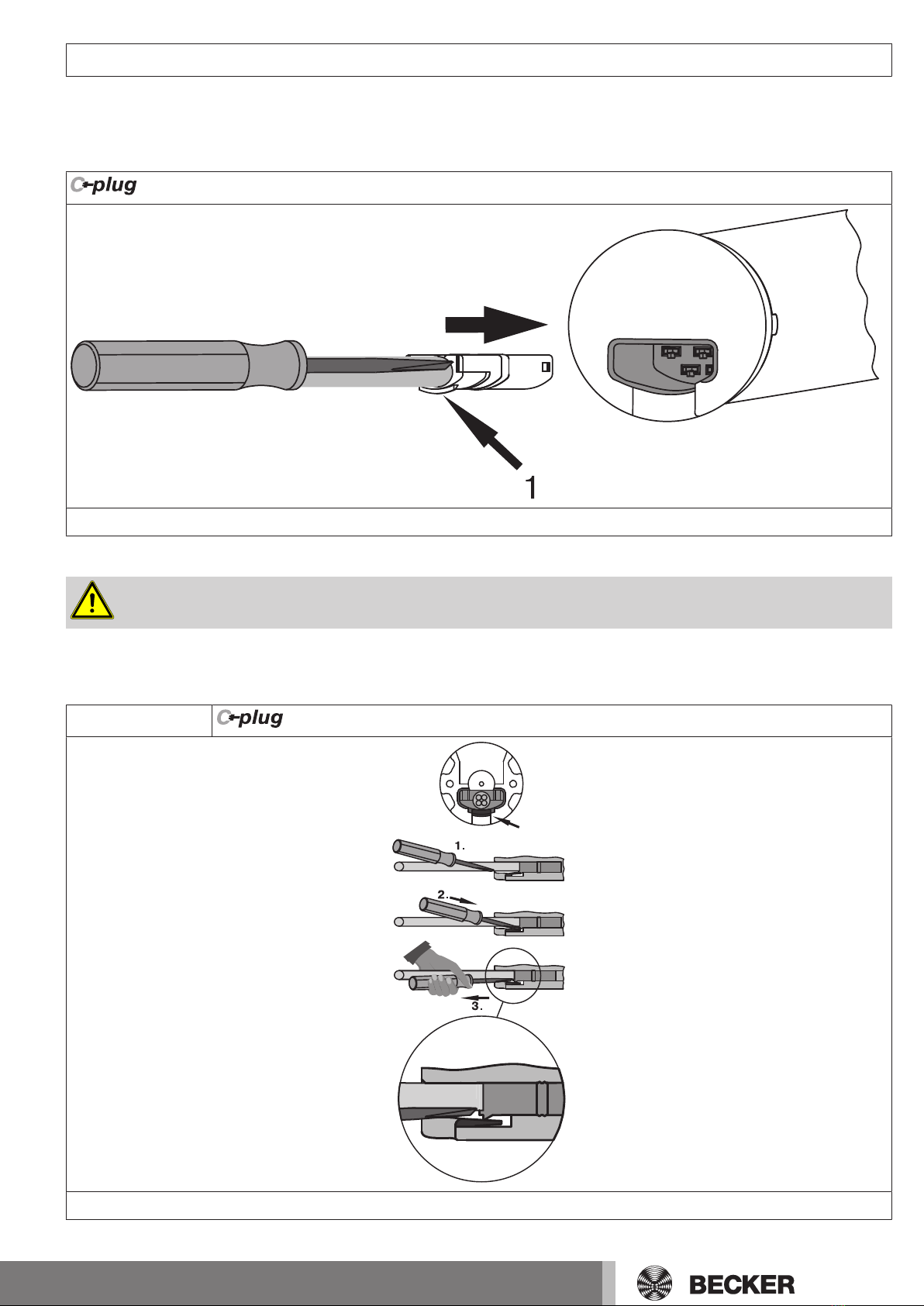
Assembling the plug-in connecting cable
Insert the dead connecting cable into the drive head until the locating lug clicks into place in the drive. If necessary, use a suitable
flathead screwdriver to assist with insertion. Set the screwdriver into one of the two plug grooves provided for this purpose.
Check that the cable is properly engaged.
1 = locating lug
Disassembling the plug-in connecting cable for tubular drives dia. 35.
Caution
Prior to disassembly, the power supply to the connecting cable must be disconnected.
Insert a suitable flathead screwdriver between the locating lug and the snap-in pin, so that the snap-in pin releases the locating lug
from the plug.
Now you can pull out the connecting cable along with the flathead screwdriver.
dia. 35
A
A = snap-in pin
7

Disassembling the plug-in connecting cable for tubular drives dia. 45 and dia. 58
Caution
Prior to disassembly, the power supply to the connecting cable must be disconnected.
Insert a suitable flathead screwdriver right into the recess of the locating latch, so that the latch releases the locating lug from the
plug.
Now you can pull out the connecting cable along with the flathead screwdriver.
dia. 45 and dia. 58
1.
2.
A
A = locating latch
Installation
Assembling the drive
Attention
To connect the drive to the driven part, solely mechanical accessory components made by
the drive manufacturer from the current product catalogue may be used.
Prior to mounting, the fitter must ensure that the masonry and the system being motorised are sufficiently robust (drive torque plus
weight of the shading solution).
Caution
Electrical connections may only be carried out by a qualified electrician. Prior to assembly,
the power supply must be disconnected and secured. Please give the enclosed connection
information to the responsible electrical contractor.
Calculate the space required at the side (M) by measuring the drive head and wall
bracket. The clear dimension of the box (X) minus the space required at the side (M)
and idler (G) gives the length (L) of the barrel: L=X-M-G.
The space required at the side (M) varies depending on the combination of drive and
wall bracket.
Then mount the wall bracket and idler. Ensure that the barrel is aligned at right angles to the wall and that sufficient axial play is al-
lowed for the mounted system.
8
Attention
For PR+SMI
When using anti-lifting devices, closed brackets must be fitted. The tubular drive presses
the closed curtain down to make it difficult for people to reach under it or raise it. Only use
curtains made of sufficiently strong material, such as aluminium, steel or wood. To prevent
damage to the curtain it must run in guide tracks from top to bottom.
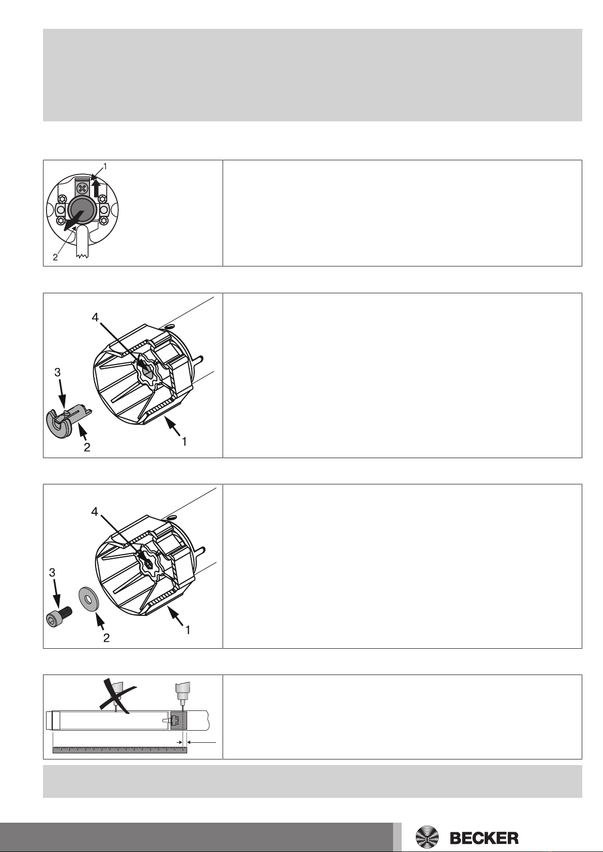
Undoing the mounting pin
When pushed in, the mounting pin (2) locks automatically. To undo the mounting pin
(2), push the tab washer (1) upwards and pull out the mounting pin (2).
Assembling the drive adapter with drive adapter safety catch
Put the drive adapter (1) onto the drive shaft of the tubular drive. You can see which
way to insert the safety catch (2) from its shape. When inserting the drive adapter
safety catch (2) into the hole (4), make sure that the locking lug (3) engages. You will
hear a click. Check that the safety catch is securely in position by pulling on the drive
adapter (1).
Assembling the drive adapter with screw connection
Put the drive adapter (1) onto the drive shaft of the tubular drive. For the assembly,
use an M6 x 12 screw (3) with appropriate washer (2) and suitable screw retainer.
Threaded hole (4)
Securing the drive against axial displacement
-10 mm
In order to secure the drive against axial displacement, we recommend screwing the
drive adapter to the tube.
Attention
When drilling into the barrel, never drill near the tubular drive!
9

Fixing the drive adapter to the barrel dia. 35 and dia. 45 and dia. 58
Size of drive
[mm]
Diameter of barrel
[mm]
Torque
max. [Nm]
Fastening screws
for drive adapter (4 pc.)
dia. 35 40 mm plastic drive adapter 13 Self-tapping screw
dia. 4.8 x 9.5mm
dia. 45 50-70mm plastic drive adapter 25 Self-tapping screw
dia. 4.8 x 9.5mm
dia. 45 50-85mm plastic drive adapter
for obstacle detection
40 Self-tapping screw
dia. 4.8 x 9.5mm
dia. 45 50 - 85 mm diecast drive adapter 50 Self-tapping screw
dia. 4.8 x 9.5mm
dia. 58 85-133mm aluminium drive adapter 120 Countersunk screw
M8 x 16mm
dia. 58 63-120mm diecast drive adapter 120 Self-tapping screw
dia. 6.3 x 13mm
We also recommend screwing the idler to the barrel.
Attention
Do not hammer the tubular drive into the tube or drop it into the barrel! The curtain can only
be secured using springs or rigid shaft connectors.
Mounting the drive in the tube
For profile tubes:
In the case of some drive adapters, tolerances of the groove widths in different bar-
rels can be offset by rotating the drive adapter into a different groove recess. These
groove recesses have different sizes and allow a perfect fit for the drive.
For round tubes:
First notch the tube on the motor side, so the lug of the thrust ring can also be pushed
into the tube. There must be no play between the lug of the thrust ring and the tube.
Assemble the tubular drive with the relevant thrust ring (1) and drive adapter (2). In-
sert the tubular drive with the pre-assembled thrust ring and drive adapter into the
tube to achieve a form fit. Ensure that the thrust ring and drive adapter are secure in
the tube.
Mount the assembled unit comprising barrel, tubular drive and idler on the box, and secure the drive according to the type of wall
bracket fixing with a split or spring pin.
Position the barrel so that the roller shutter curtain can be attached with springs or fit the rigid shaft connectors in accordance with
the manufacturer's instructions.
10
This manual suits for next models
23
Table of contents


