BECKWITH ELECTRIC BlueJay M-2911 User manual

BlueJay™Wireless
Data Transceiver
M-2911
CONTROLS
• Provides direct sequence spread spectrum peer-to-peer, point-to-
point, point-to-multipoint and master/slave high speed (1 Mbps) data
transmission rates at ranges up to 1500 feet
• Interfaces using either a RS-232, RS-422 or RS-485 connection at
interface baud rates between 300 and 115.2 Kbps
• Substation hardened to withstand temperatures from -40 to +80
degrees C and humidity up to 95%
• No user license required, interfaces with almost any legacy IED

M-2911 BlueJay Wireless Data Transceiver
–2–
WARNING
This equipment has been tested and found to comply with the limit requirements, pursuant to Part 15.247 of
the FCC Rules. These limits are designed to provide reasonable protection against harmful interference when
the equipment is operated in a commercial environment. This equipment generates, uses, and can radiate
radio frequency energy, and, if not installed and used in accordance with the instruction manual, may cause
harmful interference to radio communications. Operation of this equipment in a residential area is likely to
cause harmful interference in which case the user will be required to correct the interference at his own
expense.
Only the antenna provided is authorized for use with the M-2911. If the antenna is lost or damaged, please
contact Beckwith Electric Co., Inc. to secure a replacement antenna.
This product generates, uses, and can radiate radio frequency (RF). If it is not installed and used in
accordance with the operating instructions, it can cause harmful interference to communications. If this
equipment causes harmful interference to radio or television reception, the user should try and correct the
interference by:
• Reorienting or relocating the receiving/transmitting antenna
• Increasing the separation between the equipment and the M-2911
• Connecting the equipment into an outlet on a different circuit from the M-2911.
If these do not correct the interference, consult an experienced radio/television technician for assistance.
Correcting such interference is the responsibility of the user, not the manufacturer.
Changes or modifications not expressly approved by Beckwith Electric Co., Inc. may void the user's
authority to operate the equipment.
FCC Radiation Exposure Statement
This equipment complies with FCC radiation exposure limits set forth for uncontrolled equipment. This
equipment should be installed and operated with a minimum distance of at least 20 cm between the radiator
and person's body (excluding extremities) and must not be located or operated with any other antenna or
transmitter.

–3–
M-2911 BlueJay Wireless Data Transceiver
The M-2911 BlueJay™Wireless Data Transceiver is a self-contained short-range wireless communication
device (SRD) that is used for transferring serial communication data between Intelligent Electrical Devices
(IEDs) and computers hosting control software in an industrial environment. The M-2911 is based on an
Intersil direct sequence spread spectrum chip set that operates in the 2.4 GHz ISM band. The M-2911 design
meets the category for low power devices (LPDs) standard requirement for license-free operation.
Interface
The M-2911 is equipped with two serial data connectors, one is a DE-9 connector for use with an RS-232
serial data port and the other is a 6-pin bare wire Phoenix–type connector for use with an RS-422/RS-485
(twisted shielded pair) serial data ports. Only one port can be used at a time. Each port is capable of serial
data speeds of up to 115 kbps.
Data Transmission:
• Error Detection – 16 bit CRC (10-5 BER at –70dBm)
• Maximum throughput – 1 Mbps RF, 300 to 115.2 Kbps interface baud rate
Communication
The M-2911 conditions the data and transmits it over a half-duplex direct sequence spread spectrum radio
operating in the 2.4 GHz ISM band. The over-the-air data rate is 1 Mbps.
Transmit:
• Frequency Range – 2400 MHz to 2483.5 MHz
• Output Power – 30 mW
• Modulation – DBPSK
• Occupied Bandwidth – 20 MHz
• Spurious Emissions – 50 mV/meter
• Harmonic Emissions – 500 uV/meter
• Spreading Method – Direct Sequence 11 bit code
• Center Band – Carrier 2.450 GHz
Receive:
• Sensitivity – -93 dBm
• Selectivity – 25 MHz
The M-2911 BlueJay Wireless Data Transceiver must be used with a cable extension if the M-2911 is
mounted inside a metal enclosure. Antennas must be oriented in the same plane and located in view of the
corresponding M-2911. Beckwith Electric antenna and cable accessories are listed below.
■NOTE: For maximum range, all antennas must be oriented in the same plane.
Accessories
M-2924-4R – 4 foot cable extension for provided antenna (1/4 wave dipole)
M-2924-4S – 4 foot cable extension for optional antennas
■NOTE: Both optional antennae will require the M-2924-4S at a minimum.
M-2924-10 – 10 foot cable extension for optional antennas
M-2924-25 – 25 foot cable extension for optional antennas
421-00228 – 9 dB Omni-directional outdoor antenna

M-2911 BlueJay Wireless Data Transceiver
–4–
M-2933-10 – 9 dB Omni-directional outdoor antenna with 10' cable
M-2933-25 – 9 dB Omni-directional outdoor antenna with 25' cable
■NOTE: 19 dB antenna is for special applications. Please contact Beckwith Electric if the omnidirectional
antennas do not meet your needs.
421-00227 – 19 dB Parabolic antenna
M-2934-10 – 19 dB Parabolic antenna with 10' cable
M-2934-25 – 19 dB Parabolic antenna with 25' cable
Power
The M-2911 includes a self-contained switching power supply that supplies the data and RF circuitry with
regulated dc power as required.
Power Requirements:
• Operating Voltage – +7 to +60 V dc
• Transmit Current – 2 W (300 mA @ 7 V)
• Receive Current – 2 W (300 mA @ 7 V)
• Idle Current – 1 W (150 mA @ 7 V)
• Sleep Current – 0.2 W (30 mA @ 7 V)
The power supply is a UL listed wall transformer that delivers between 7 and 60 V dc at a maximum power
output of 2.5 Watts. The power supply is equipped with an external 5.5 mm outside diameter, 2.1 mm inside
pin, center positive connector.
Figure 1 Power Supply Connector Polarity
Alternate Power
Any power source that meets the above requirements may be used to power the unit. For example, a
cigarette lighter DC adapter (which may be purchased from any electronics retailer) can be used, provided
that the correct polarity as stated above is observed. A battery source may also be used if the battery is
sized to meet the power requirements given.
Configuration
The M-2911 BlueJay™ Wireless Data Transceiver is factory-configured to provide optimal communications
for the widest possible user base. With the exception of Addressing, Baud Rate, and Interface settings, most
settings will never need to be adjusted. We recommend that all other settings be left as shipped unless
communications problems are noted.
If factory configurations are required to be altered, we recommend contacting Beckwith Electric prior to
attempting to adjust the settings in question.

–5–
M-2911 BlueJay Wireless Data Transceiver
Configuring the M-2911
To configure the M-2911, the unit must be placed in the AT-Command Mode. Placing the M-2911 in the AT-
Command Mode is accomplished utilizing a terminal emulator such as Microsoft®HyperTerminal™.
Current versions of Microsoft Windows™ include HyperTerminal (a terminal emulation program designed for
modem communications between a PC and an Intelligent Electric Device (IED). The Hyper Terminal program
can generally be found under Start/Program Files/Accessories/Communications. To set up the Hyper
Terminal program to place the M-2911 in the AT-Command Mode, perform the following:
1. Start the Hyper Terminal program.
2. The program will display a prompt asking for a name and icon choice for the new connection.
Enter a name (such as M-2911), then select OK. The program will display the Connect To dialog
box.
3. From the Connect Using drop-down menu, select COM1 (or the COM port to which you will be
connecting), then select OK. The program will display a COM Properties dialog box.
4. Set the COM Port Settings as follows:
Bits per Second: 9600
Data Bits: 8
Parity: None
Stop Bits: 1
Flow Control: None
■NOTE: The PC or laptop computer does not have to be connected to the M-2911 to open the COM port.
5. Select OK. The connection has been configured and opened.
To place the M-2911 in AT-Command Mode, perform the following:
1. Connect the M-2911 (using a straight-through RS-232 cable) to a PC or laptop computer running a
terminal emulator program (such as Microsoft HyperTerminal) set to 9600 bps, No Parity, One
Stop Bit.
2. Apply power to the M-2911. When prompted onscreen, type "+++". All three LEDs on the unit
should illuminate while in "Command Mode".
The M-2911 will enter AT-Command Mode and respond with "OK". The user can then enter AT
Commands by typing them into the terminal window and pressing Enter.
3. When the configuration of the M-2911 has been completed, then exit the configuration mode and
save any changes made by entering ATZ<ENTER>
AT Commands
Addressing (Unit Address, Destination Address, Multicast Address)
ATS=nnn Unit (Source) Address
ATD=nnn Destination Address
ATM=nnn Multicast Address
The M-2911 BlueJay™ Wireless Data Transceivers are generally used in pairs, serving as a simple "wireless
extension" for a RS-232 (or RS-422 or RS-485) connected piece of equipment.
The most simple application is a pair of M-2911s inserted into a cable connection between one piece of
equipment (perhaps an RTU) and another (perhaps an IED). In this case, the units are configured with
corresponding addresses. For example, the first unit may be set to Unit Address 1, and the second to Unit
Address 2. Then the first unit would have Destination Address 2, while the second could have Destination
Address 1. So when the first unit transmits data, it "labels" it to be received by the M-2911 with Unit Address
2, while data transmissions from the second unit would be labeled for reception by the M-2911 with Unit
Address 1. In this way, they exchange data between the pair and no other M-2911 in the area.

M-2911 BlueJay Wireless Data Transceiver
–6–
Generally, the other parameters (Baud Rate, Data Bits, Parity, Packet Size, Time-out, etc.) would be
identical, though there are instances when this would not be the case. Those instances will be explained in
greater detail later on in this section.
Another M-2911 application would be to configure a "Network" of units, where a Master unit polls several
Slave units. This would be the case where there is a Data Collection unit communicating with several IED’s.
In this case, the Multicast Address would be used to allow one unit to communicate with several others
simultaneously. For this example, the Master Unit would be set with a normal Unit Address (1-250), which is
the address the Slave units would use for their Destination Address. The Master unit would have a
Destination Address between 251 and 254, which are the "Multicast Addresses". These addresses are
distinct in that transmissions sent to these addresses are not acknowledged by the receiving M-2911, which
allows data to be sent to many Slave units without causing data clashes since these Slave units do not
attempt to acknowledge the Master units transmission. The Slave units would all have their Multicast
Address set to the selected Multicast Address (251-254), while their Destination Address would all be set to
the Master units address (1-250). They would each be given a separate Unit Address (1-250) different from
the Master unit and other Slave units.
For this application, data sent from the Master unit would be passed out to all Slave units (to the individual
IEDs) simultaneously, while response data from a Slave unit would be passed back to the Master unit (to the
RTU).
For this application, the data transfers must involve a protocol where each Slave unit can be addressed
individually within the data transferred to all units, such that only one of the Slave units at a given time will
accept, and respond to, the data.
Address 255 is a special case in that all units within the range of transmission of a unit set to Destination
Address 255 will receive these transmissions, no matter what their Unit or Multicast Address is. This is the
"Broadcast Address", and is used for system-wide commands, for example Load Reduction commands. In
this case also, units receiving data with this Broadcast Address will not attempt to acknowledge this
transmission.
Baud Rate:
ATB=nnnnnn 4800, 9600, 14400, 19200, 28800, 38400, 57600, 76800, 115200
Generally M-2911s that communicate with each other would have the same baud rate, as dictated by the
equipment to which they are attached.
The baud rate is selectable between 4800 and 115,200 bits per second (bps), over the standard baud rates:
4800, 9600, 14400, 19200, 28800, 38400, 57600, 76800, and 115200.
In some applications, IEDs in a system may not have equal baud rates, and in some instances, the M-2911
can be used to convert between these baud rates. The limitation of converting between baud rates is that the
data transferred must be in packets of less than 128 bytes (including packet overhead such as addresses
and checksums, etc.), as this is the size of the data buffer within the M-2911. If data is transferred in such
packets, and the protocol waits for acknowledgment (or response) to each packet, the M-2911 will provide for
baud-rate conversion over their operating range (4800-115200 bps). In such a situation, data will flow into the
faster-set unit in less time than it flows out of the slower-set unit, and communication speed will be limited to
the rate of the slower unit. For this application, the receive time-outs in the protocol must be configured to
tolerate the slower rate.
Parity:
ATP=x
E, O, N
(Even, Odd, None)
Most IEDs no longer use Parity (an extra bit added to each character to serve as a simple checksum), and
send just the eight data bits preceded by a Start Bit and are followed by a Stop Bit. For these IEDs, the Parity
is set to NONE.
For those devices that still utilize parity, the M-2911 should be set with the same parity – EVEN or ODD.
Even parity is where the appended parity bit serves to keep the total number of ‘1’ bits in the data and parity
an even number (if the data has an odd number of "1" bits the parity bit is set to "1", if the data has an even
number of "1" bits the parity bit is set to ‘0’).

–7–
M-2911 BlueJay Wireless Data Transceiver
The M-2911 does not transmit the parity between units, so it is possible to have different parity settings on
the different units, to match equipment which must have a certain parity setting. The M-2911s then also
serve as ‘Parity Converters’.
If possible, disabling parity (setting it to NONE on both the M-2911s and connected equipment) will speed up
communication, since there are 10 bits per character with no parity, and 11 bits per character in EVEN or
ODD parity.
Transmit Retries:
ATR=n
0
to
9
The M-2911 utilizes an acknowledged-transfer protocol, where each data packet sent from one unit to
another is acknowledged by the receiving unit. If the sending unit does not receive an acknowledge packet
within 2 milliseconds, it will retransmit the data as many times as specified in this parameter. A setting of 0
indicates the data packet will be transmitted only once. A setting of 1 means it will be retransmitted one time,
etc. Note that if the sending unit has a destination address of 251 to 254 (Multicast) or 255 (Broadcast), it will
always retransmit the data packet as many times as specified by this parameter, since there will never be an
acknowledge packet for these addresses. The default value is 4, indicating the data will be sent a maximum
of five total times (4 retries).
Interface:
ATI=RS232, ATI=RS422, ATI=RS485
The M-2911 can communicate using RS-232 ("five wire" mode – TxD, RxD, RTS, CTS, and GROUND),
RS-422 (TxD+, TxD-, RxD+, RxD-, GROUND), or RS-485 (D+, D-, GROUND). This parameter selects which
interface mode is active. The RS-232 signals are available from the 9-pin DB female connector, while the
RS-422/485 signals are on the terminal strip. The unit should have only one type of communications cable
connected at a time.
RS-232 Mode:
ATI=CTSx
L, H, F (Low, High, Flow-thru)
The RS-232 interface includes one ‘Hardware Flow-Control’ signal – CTS (Clear-To-Send from the M-2911 to
the connected equipment).
The CTS output is used to gate data into the M-2911 from the IED (using TxD). When set to Low, the signal
is forced Inactive (negative voltage). When set to High, the signal is forced Active (positive voltage).
Most modern protocol-based equipment no longer use these signals, and in many cases, they can simply be
ignored. If the connected equipment does not use Flow Control, the default setting of CTSH (CTS forced
active High) are suitable. If hardware flow control is used, then set this parameter as required by the
connected equipment.
RS-422/485 Mode:
ATI=TXO, ATI=TXLnnnms, ATI=TXHnnnms
(1 to 200 milliseconds)
In RS-422 or RS-485 mode, the Transmit Data lines (TxD+ and TxD-) can be forced on (always driven –
TXO), or gated on for a certain “Lead Time” before the start of data transmission (TXL = nnn for nnn
milliseconds) and held on for a certain “Hold Time” after the end of data transmission (TXH = nnnn for nnn
milliseconds.) The resolution of these parameters is 1mS, so the actual times will be the closest 1mS to that
set.

M-2911 BlueJay Wireless Data Transceiver
–8–
Intercharacter Time-out:
ATT=nnC, ATT=nnn ms
1
to
50
Character Times, or
1
to
199
milliseconds
This parameter sets the time that the M-2911 will wait after receiving characters to send a packet. If data
bytes are coming in as a constant stream, the M-2911 will transmit a data packet each time the number of
bytes specified by the ATN parameter is received. If there is a pause in the data (such as at the end of an IED
packet), the M-2911 will transmit the bytes received after the ATT delay. As with the RS-422/485 transmit
gating parameters, this can be specified in Character Times or milliseconds. The default value is 3 Character
Times, or 3mS at 9600 bps. A low setting is desirable since it allows data to be sent as soon as possible, but
at times, a high setting is necessary to permit data to be collected into reasonably sized packets to allow for
better efficiency.
Maximum Packet Size:
ATN=nn 1 to 64 Characters
The M-2911 sends data in packets of multiple bytes, and will transmit the data packet after a specified
number of bytes is received (or if there is a delay greater than the ATT Timeout described above). The
number of bytes can be specified between 1 and 64 Characters, with a default value of 64. In general the
largest size is desirable, but in some cases (for example a protocol with fixed number of bytes in each
transfer) a setting to match the IED characteristics may be better.
View Settings:
ATV
This command will display the model name, software version, serial number, and basic settings of the unit.
Exit and Save:
ATZ
▲CAUTION: This command MUST be sent to the unit after any changes are made to save and exit from
command mode, otherwise all information will be lost.
Typical Connections Guide
The M-2911 can be applied in one of two methods. An example of each connection configuration utilizing a
Beckwith Electric M-2001B as the target IED is given below:
1. Point-to-Point Configuration: In the Point to Point configuration, two M-2911s are configured to
communicate only to each other. One is connected to a PC, modem, etc. and the other is
connected to an IED.
Detailed elements of a typical Point-to-Point configuration are as follows:
a. One M-2911 is connected to a PC COM port using a straight-through RS-232 cable.
b. The second M-2911 is connected to the RS-232 port of a M-2001B Tapchanger Control
using an RS-232 straight through cable and gender changer.
Communications can now be established between the PC and M-2001B as if they were directly
connected using a RS-232 cable. In this example, if the M-2001B TapTalk Communications
Software were to be used, the user would select the COM Port the M-2911 is connected to on the
PC side, and then connect normally to the M-2001B.
2. Point-to-Multipoint configuration (also known as Master/Slave): In the Point-to-Multipoint
configuration, one M-2911 is configured as the Master unit with multiple-connected IED units
configured as Slaves (see AT Commands, Addressing section for Master/Slave setup). This
configuration may be used where, for example, the Master unit is located in a control house and
the slaves are spread out throughout a substation yard.

–9–
M-2911 BlueJay Wireless Data Transceiver
Detailed elements of a typical Point to Multipoint configuration are as follows:
a. One M-2911 (Master) is connected to the RS-232 port of a modem in the control house of a
substation using a straight through RS-232 cable.
It is configured as a master unit. (See the Addressing section under AT commands for
details) i.e. ATS=1, ATD=251, ATM=252.
b. Nine M-2001B Regulator Controls are located throughout a substation yard, each with an
M-2911 connected to it using a straight through RS-232 cable connected to the M-2001B
COM 1 Port.
Each M-2911 is configured as a Slave unit. (See the Addressing section under AT
commands for details) i.e. ATS=2 to 250, ATD=1, ATM=251
c. At a remote location, an RTU has been configured to dial the modem located at the control
house and poll each unit at the substation at 5 minute intervals. For this application to
operate successfully, the RTU cannot poll all units simultaneously.
In addition to these methods, the M-2911 can be configured using RS-485 or RS-422. See the following
figures for examples.
Application Information
tiucriC langiS S9-BD
232-SR
BBXRataDevieceR2niP
ABXTataDtimsnarT3niP
ACSTRdneSottseuqeR7niP
BCSTCdneSotraelC
DCRTDydaeRlanimreTataD4niP
FCDCDtceteDreirraCataD
BADNGdnuorGlangiS5niP
Table 1 RS-232 Communication Port Signals

M-2911 BlueJay Wireless Data Transceiver
–10–
RS-232 Communication
1
2
3
4
5
6
7
8
9
1
2
3
4
5
6
7
8
9
RX
TX
SGND
RTS
CTS
RX
TX
SGND
RTS
CTS
M-2911
DB9S
PC
DB9P
Figure 2 RS-232 Pin-out
RS-232 is point-to-point (four wires plus shield) from M-2911 to one IED.
RS-422 Communication
1
2
3
4
5
6
SGND
D-
D+
D-
D+
SGND
M-2911
6 Pin Terminal
Block P1
RS-422
Connection
1
2
3
4
5
6
SGND
D-
D+
D-
D+
SGND
Shielded Twisted Pair
RX
TX
TX
RX
Figure 3 RS-422 Pin-out
RS-422 is a dual shielded, twisted pair (four wires plus two shields), from M-2911 to one IED.
–11–
M-2911 BlueJay Wireless Data Transceiver
1
2
3
4
5
6
SGND
D-
D+
D-
D+
SGND
M-2911
RS-422
RX
TX
IED
200
200
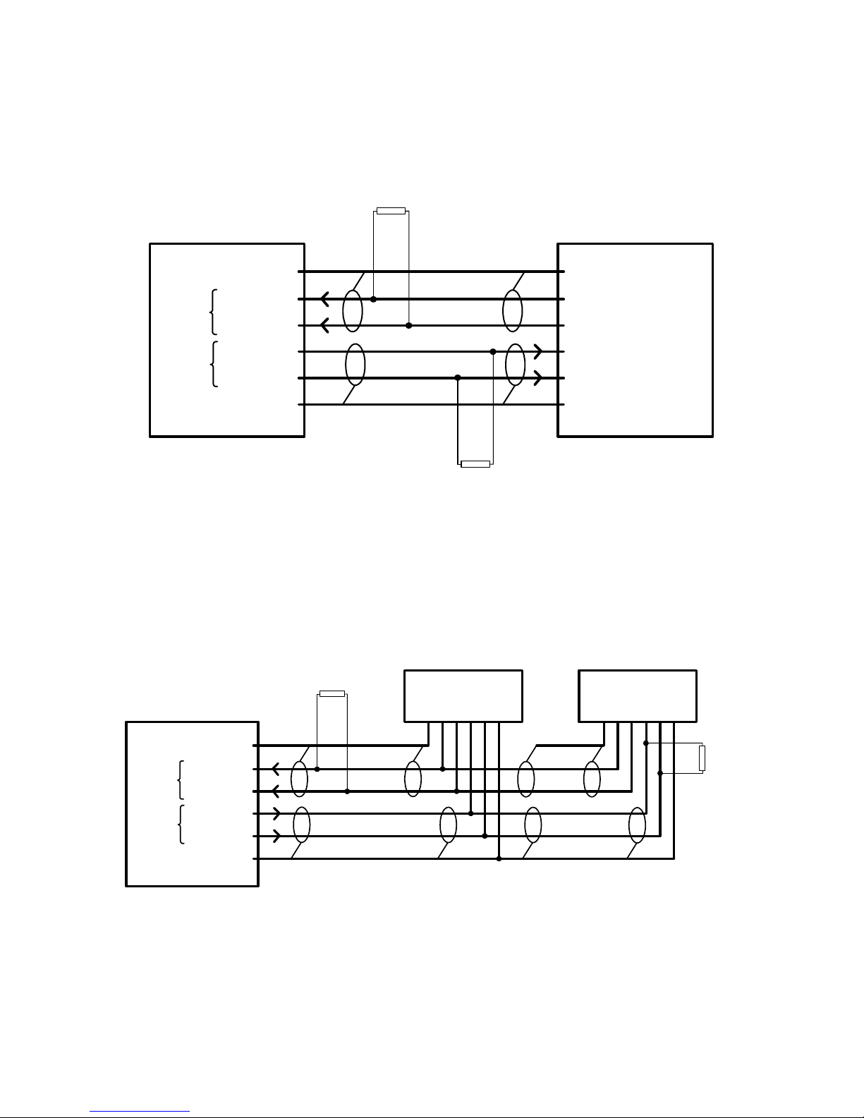
Figure 4 RS-422 Example IED
RS-422 network is a dual shielded twisted pair (four wires plus two shields), from M-2911 to IEDs in parallel.
1
2
3
4
5
6
SGND
D-
D+
D-
D+
SGND
M-2911
RS-422
RX
TX
200
200
IEDs In Parallel
IEDIED
Figure 5 RS-422 Network Example IED's in Parallel

M-2911 BlueJay Wireless Data Transceiver
–12–
RS-485 Communication
6
5
4
3
2
1
SGND
D+
D-
N/C
N/C
N/C
M-2911
6 Pin Terminal
Block P1
RS-485
Network
SGND
D+
D-
Figure 6 RS-485 Pin-out
RS-485 is a single shielded twisted pair (two wires plus shield), from M-2911 to IEDs in parallel.
M-2911
RS-485
200
200
IEDs In Parallel
IEDIED
6
4
5
1
2
3
SGND
D -
D+
N/C
N/C
N/C
RX/TX
Figure 7 RS-485 Example IEDs in Parallel

–13–
M-2911 BlueJay Wireless Data Transceiver
Optimal Antenna Configuration
A variety of antenna types can be used with the M-2911. The antennas available from Beckwith Electric are
FCC qualified for use with our product. Use of an antenna not supplied by Beckwith Electric could violate
FCC licensing and result in fines to the user. The antenna supplied with the unit is an omnidirectional
antenna. An omnidirectional antenna is so named because it is designed to radiate equally in all directions
horizontal to the antenna. These antennas have been designed to radiate in a horizontal pattern, which is
best approximated by a toroid, or “doughnut” illustrated in Figure 7. This is also why most omnidirectional
antennas are rated to have a three dB gain over a true spherical radiator. The antenna appears to have a
power gain of two times (3 dB), compared to a true spherical radiator.
Optimum performance of Beckwith Electric-supplied antennas is obtained when the main axis of the antenna
is located perpendicular to the Earth’s surface. This allows the toroidal pattern to radiate the maximum range
in each dimension. When the RF energy of the radiation pattern contacts ground, or a grounded surface, it is
absorbed in varying degrees depending on the conductivity of the surface. It is important to have a clear
view, or “line-of-sight” between antennas as illustrated in Figure 8. Any obstructions between the antennas
can absorb some energy, and can reduce the range of operation. Also, if a grounded plane is located parallel
to and close to the antenna, such as a wall located next to the antenna, it can change the impedance match
between the antenna and free-space. This condition can severely reduce the range that can be normally
obtained in unblocked directions. A rule of thumb is to ensure that any grounded objects are kept at least 10
wavelengths (50 inches for 2.4 GHz) away from the antenna in the plane of radiation (Figure 8). 50 inches is
only a guideline, and may be shortened if extreme range is not required. Some experimentation with antenna
location will be needed to optimally set up wireless in a substation environment.
The following should be considered when planning a wireless project:
1. The resonant frequency of the water molecule is within the 2.4 GHz band, which can cause a
reduction in range during rainy weather.
2. Trees (especially pine trees) can have >80% water content, and as such can be a barrier to
wireless signals. As long as antennas have a direct line of sight, trees should not cause a
problem.
3. Proximity of the wireless project to cell towers, 2.4 GHz telephones, WiFi access points, or
Bluetooth wireless devices.
If you are experiencing difficulty communicating through the M-2911s, ensure that the antennas are:
• In direct line of sight with each other.
• Oriented vertically with respect to earth.
• Within 1500 Ft.
You may be encountering interference from another source. Some examples of interference are
cell towers, 2.4 GHz telephones, WiFi access points, or Bluetooth wireless devices. If the
interference cannot be compensated for by relocating the antennas or reducing the distance
between them, then other antenna types may be necessary. Please contact Beckwith Electric if
you would like to discuss other antenna options.
M-2911 BlueJay Wireless Data Transceiver
–14–
BlueJayTM
Wireless
M-2911
Made in U.S.A.
PWR
RX
TX
CO. INC.
ELECTRIC
BECKW ITH
M-2911
Top View
Side View
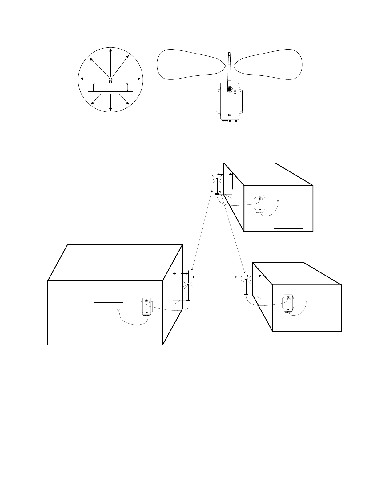
Figure 8 Top and Side View
BlueJayTM
Wireless
M-2911
Made in U.S.A.
PWR
RX
TX
CO.INC.
ELECT RIC
BECKW ITH
IED
50"
*
Sub Station
Control Hous e M-2911
Blue JayTM
Wire less
M-2911
Made inU.S.A.
PWR
RX
TX
CO.INC.
ELECTRIC
BECKWITH
IED
or
MODEM
50"
*Recommended 50"
from wall of building
BlueJayTM
Wire less
M-2911
Madein U.S.A.
PWR
RX
TX
CO.INC.
ELECTRIC
BECKWIT H IED
50"
*
M-2911
M-2911
No Obstructions
Between Antennas
Figure 9 Line of Site Orientation of Antennas

–15–
M-2911 BlueJay Wireless Data Transceiver
Environmental
Temperature: Proper operation maintained from –40°C to +80°C.
Humidity: Proper operation is maintained up to 95% relative humidity (non-condensing).
Environmental Protection: The power supply printed circuit board is conformally coated to inhibit fungus
growth.
Enclosure: 1/16" Aluminum.
Physical
Size: 5.88" high (with antenna 9.43") x 3.88" wide x 2.5" deep (14.58 cm (23.1) x 9.9 cm x 6.13 cm). See
Figure 10 for dimensional drawing.
Weight: 2.13 oz (60 grams)
Enclosure meets requirements of IP30.
BlueJay
TM
Wireless
M-2911
Made in U.S.A.
.25
PWR
RX
TX
1.15
2.75
3.08
3.38
3.88
.93 (2X)
.38
1.00
3.62 (2X) 5.50
1.50
4.51
.56
.20 DIA
(4X)
C . INC.
ELECTRIC
BECKWITH
Figure 10 Outline Dimensions

M-2911 BlueJay Wireless Data Transceiver
–16–
Safety and Cautions
8WARNING:The installation, maintenance, and/or operation of this equipment could present
potentially unsafe conditions, including, but not limited to, electrical shock or improper voltage to
components. Improper operation could cause personal injury, death, or damage to property.
Read all safety instructions before operating the M-2911, and retain them for further reference. Follow all
operating and usage instructions, and make special note of the following safety symbols:
– This sign warns that the area is connected to a dangerous high voltage, and you must
never touch it.
– This sign means that you should refer to the corresponding section of the operation
manual for important information before proceeding.
Do not attempt to perform maintenance or service functions that are not described in the operating
instructions. Instead, refer all such service requirements to Beckwith Electric Co., Inc. Unit must be returned
for service in secure (preferably original) packaging. Shipping cost must be paid by user.
Only the antenna provided is authorized for use with the M-2911. If the antenna is lost or damaged, please
contact Beckwith Electric Co., Inc. to secure a replacement antenna.
This product generates, uses, and can radiate radio frequency (RF). If it is not installed and used in
accordance with the operating instructions, it can cause harmful interference to communications. If this
equipment causes harmful interference to radio or television reception, the user should try and correct the
interference by:
• Reorienting or relocating the receiving/transmitting antenna
• Increasing the separation between the equipment and the M-2911
• Connecting the equipment into an outlet on a different circuit from the M-2911.
If these do not correct the interference, consult an experienced radio/television technician for assistance.
Correcting such interference is the responsibility of the user, not the manufacturer.

–17–
M-2911 BlueJay Wireless Data Transceiver
Compliance
This device has been designed to operate with an antenna having a maximum gain of 19 dB. Antenna having
a higher gain are strictly prohibited per regulations of Industry Canada. The required antenna impedance is 50
ohms.
This equipment has been tested and found to comply with the limit requirements, pursuant to Part 15.247 of
the FCC Rules and Industry Canada RSS-210 and ICES-003. These limits are designed to provide
reasonable protection against harmful interference when the equipment is operated in a commercial
environment. This equipment generates, uses, and can radiate radio frequency energy, and, if not installed
and used in accordance with the instruction manual, may cause harmful interference to radio communica-
tions. Operation of this equipment in a residential area is likely to cause harmful interference in which case
the user will be required to correct the interference at his own expense.
This device complies with Part 15 of the FCC Rules. Operation is subject to the following two conditions:
1. this device may not cause harmful interference, and
2. this device must accept any interference received, including interference that may cause
undesired operation.
Patent & Warranty
■NOTE: Changes or modifications to the unit not expressly approved by Beckwith Electric Co. may void
the user's authority to operate the equipment.
U.S. Patent for the M-2911 BlueJay™ Wireless Data Transceiver is pending.
The M-2911 BlueJay Wireless Data Transceiver is covered by a five year warranty from the date of shipment.
Specification is subject to change without notice.

I
S
O
9
0
0
1
:
2
0
0
0
R
e
g
i
s
t
e
r
e
d
BECKWITH ELECTRIC CO., INC.
6190 - 118th Avenue North • Largo, Florida 33773-3724 U.S.A.
PHONE (727) 544-2326• FAX (727)546-0121
E-MAIL [email protected]
WEBPAGE www.beckwithelectric.com
800-2911-SP-02MC1 11/04
© 2002 Beckwith Electric
Printed in U.S.A. (8.26.03)
Other manuals for BlueJay M-2911
1
Table of contents
Other BECKWITH ELECTRIC Transceiver manuals


