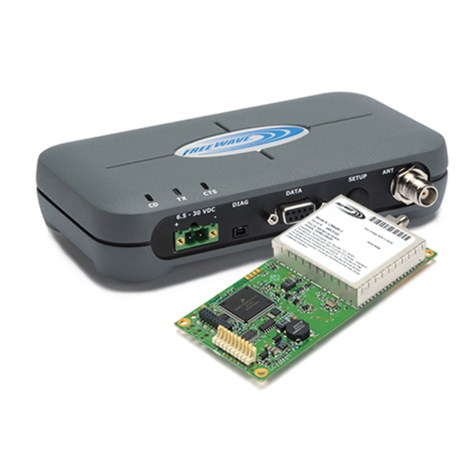
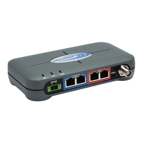
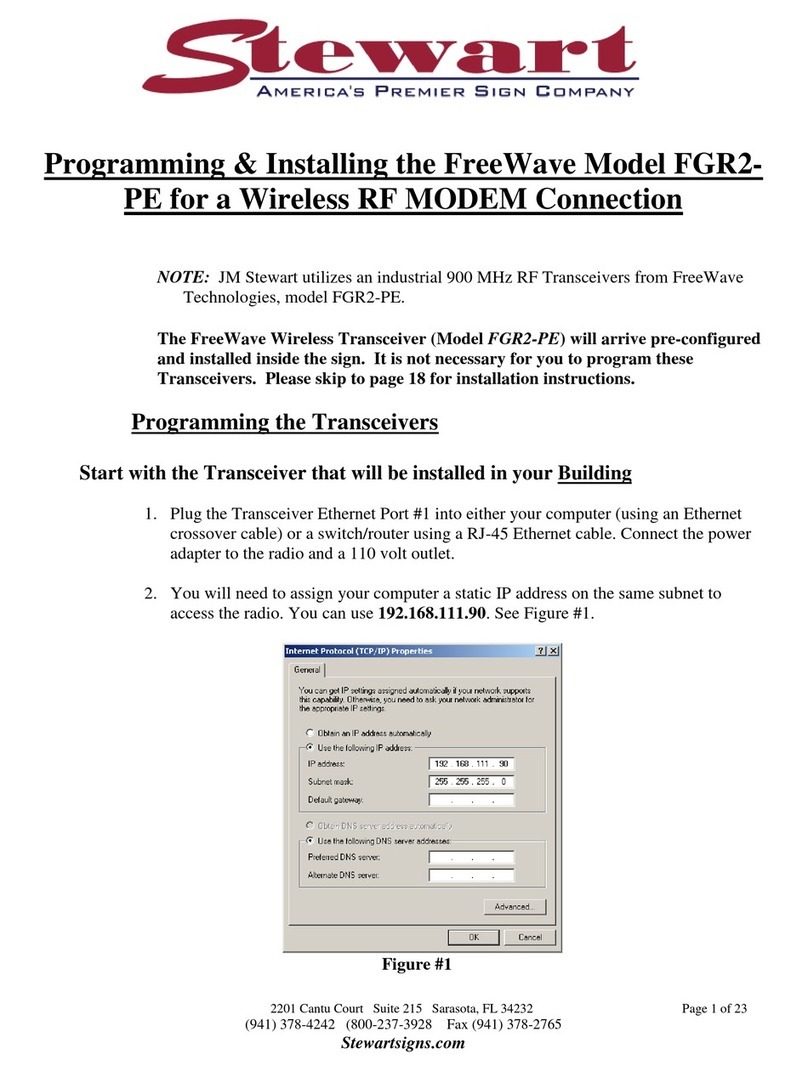
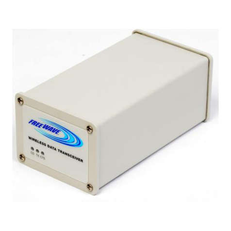
FreeWave Spread Spectrum User manual

Spread Spectrum Wireless Data Transceiver User Manual
LUM0002AG Rev D Version 7.0 i
Spread Spectrum
Wireless Data Transceiver
User Manual
Version 7.0, Revision D
FreeWave Technologies, Inc.
1880 South Flatiron Court
Boulder, CO 80301
(303) 444-3862
(303) 786-9948 Fax
www.FreeWave.com
SPREAD SPECTRUM WIRELESS DATA TRANSCEIVER USER MANUAL
Copyright © 1995-2009 by FreeWave Technologies, Inc. All rights reserved. Published 2009.

Spread Spectrum Wireless Data Transceiver User Manual
LUM0002AG Rev D Version 7.0 ii
WARRANTY
FreeWave Technologies warrants your FreeWave® Wireless Data Transceiver against defects in
materials and manufacturing for a period of two years from the date of shipment. In the event of a
Product failure due to materials or workmanship, FreeWave will, at its option, repair or replace the
Product. The Product must be returned to FreeWave upon receiving a Return Material Authorization
(RMA) for evaluation of Warranty Coverage.
In no event will FreeWave Technologies Inc., its suppliers, and its licensors be liable for any damages
arising from the use of or inability to use this Product. This includes business interruption, loss of
business information, or other loss which may arise from the use of this Product. Please be advised that
OEM customer’s warranty periods may vary.
Warranty Policy may not apply:
1. If Product repair, adjustments or parts replacements is required due to accident, neglect, unusual
physical, electrical or electromagnetic stress.
2. If Product is used outside of FreeWave specifications.
3. If Product has been modified, repaired or altered by Customer unless FreeWave specifically
authorized such alterations in each instance in writing. This includes the addition of conformal
coating.
Special Rate Replacement Option
A special rate replacement option is offered to non-warranty returns or upgrades. The option to purchase
the replacement unit at this special rate is only valid for that RMA. The special replacement rate option
expires if not exercised within 30 days of final disposition of RMA.
RESTRICTED RIGHTS
Any product names mentioned in this manual may be trademarks or registered trademarks of their
respective companies and are hereby acknowledged.
Information in this manual is subject to change without notice and is proprietary and confidential to
FreeWave Technologies, Inc.
This manual is for use by purchasers and other authorized users of the FreeWave® Wireless Data
Transceiver only.
No part of this manual may be reproduced or transmitted in any form or by any means, electronic or
mechanical, or for any purpose without the express written permission of FreeWave Technologies, Inc.
FreeWave’s Spread Spectrum Wireless Data Transceivers are designed and manufactured in the United
States of America.
Printed in the United States of America.
This product is licensed by The United States. Diversion contrary to U.S. law is prohibited.
Shipment or re-export of this product outside of The United States may require authorization by
the U.S. Bureau of Export Administration. Please contact FreeWave Technologies for assistance
and further information.

Spread Spectrum Wireless Data Transceiver User Manual
LUM0002AG Rev D Version 7.0 iii
UL NOTIFICATION
Models FGR2-C-U, FGR2-CE-U, FGR2-IOS-C-U, FGR2-IOS-CE-U, I2-C-U, I2-T-U, I2-IOS-C-U and I2-
IOS-T-U are suitable for use in Class 1, Division 2, Groups A, B, C, and D or non-hazardous locations
only. Input voltage for the above models is 6 to 30 volts DC.
Model FGRO9CSU is suitable for use in Class 1, Division 2, Groups A, B, C, and D or non-hazardous
locations only. Input voltage for Model# FGRO9CSU is 6 to 30 volts DC.
Model DGRO9RFS is suitable for use in Class 1, Division 2, Groups A, B, C, and D or non-hazardous
locations only.
Input voltages for Model DGRO9RFS are determined by the label on the bottom of the board. If the board
has Label A shown below the input voltage is 6 to 14 volts DC.
If the board has Label B shown below the input voltage is 6 to 14 volts DC at a maximum baud rate of
57.6 KBaud or 6 to 18 volts DC at a maximum baud rate of 19.2 KBaud, operation mode of MultiPoint
Slave or MultiPoint Slave/Repeater only.
WARNING: DO NOT REMOVE OR INSERT DIAGNOSTICS CABLE WHILE CIRCUIT IS LIVE UNLESS
THE AREA IS KNOWN TO BE FREE OF IGNITION CONCENTRATIONS OF FLAMMABLE GASES OR
VAPORS.

Spread Spectrum Wireless Data Transceiver User Manual
LUM0002AG Rev D Version 7.0 iv
FCC NOTIFICATIONS
This device complies with part 15 of the FCC rules. Operation is subject to the following two conditions: 1)
This device may not cause harmful interference and 2) this device must accept any interference received,
including interference that may cause undesired operation. This device must be operated as supplied by
FreeWave Technologies, Inc. Any changes or modifications made to the device without the express
written approval of FreeWave Technologies may void the user's authority to operate the device.
CAUTION: The FGR/DGR series transceivers have a maximum transmitted output power of 955mW.
The FGR2 series transceivers have a maximum transmitted output power of 1000mW. It is
recommended that the transmit antenna be kept at least 23 cm away from nearby persons
to satisfy FCC RF exposure requirements.
The “I”, “IM” and “I2”-series transceiver have maximum transmitted output power of
500mW. It is recommended that the transmit antenna be kept at least 23 cm away from
nearby persons to satisfy FCC RF exposure requirements.
This equipment has been tested and found to comply with the limits for a Class B digital device, pursuant
to part 15 of the FCC Rules. These limits are designed to provide reasonable protection against harmful
interference in a residential installation. This equipment generates, uses, and can radiate radio frequency
energy and, if not installed and used in accordance with the instructions, may cause harmful interference
to radio communications. However, no guarantee shall be made that interference will not occur in a
particular installation. If this equipment does cause harmful interference to radio or television reception,
which can be determined by turning the equipment off and on, the user is encouraged to try to correct the
interference by one or more of the following measures:
Reorient or relocate the receiving antenna.
Increase the separation between the equipment and receiver.
Connect the equipment into an outlet on a circuit different from that to which the receiver is
connected.
Consult the dealer or an experienced radio/TV technician for help.
Note: Whenever any FreeWave Technologies module is placed inside an enclosure a label must be
placed on the outside of that enclosure which includes the module's FCC ID.

Spread Spectrum Wireless Data Transceiver User Manual
LUM0002AG Rev D Version 7.0 v
Table of Contents
ABOUT FREEWAVE TRANSCEIVERS.................................................................................................................7
CHOOSING POINT-TO-POINT OR POINT-TO-MULTIPOINT OPERATION ........................................................................8
QUICK START ON A POINT-TO-MULTIPOINT NETWORK ..........................................................................9
POINT-TO-MULTIPOINT OPERATION LED'S. ..............................................................................................................9
QUICK START ON A POINT-TO-POINT NETWORK......................................................................................10
POINT-TO-POINT OPERATION LED’S........................................................................................................................10
CHOOSING A LOCATION FOR THE TRANSCEIVERS..................................................................................11
SETTING UP THE TRANSCEIVER USING HYPERTERMINAL ...................................................................12
ACCESSING HYPERTERMINAL’S SETUP MENU .........................................................................................................12
CONNECTING AND DISCONNECTING FROM HYPERTERMINAL...................................................................................16
TROUBLESHOOTING HYPERTERMINAL.....................................................................................................................17
SETTING UP A TRANSCEIVER...........................................................................................................................18
OPERATION MODE....................................................................................................................................................18
SET OPERATION MODE.............................................................................................................................................20
BAUD RATE..............................................................................................................................................................21
SET BAUD RATE.......................................................................................................................................................21
MODBUS RTU TIMING .............................................................................................................................................24
CALL BOOK..............................................................................................................................................................25
EDIT CALL BOOK .....................................................................................................................................................25
Programming Point-to-Point Extended Call Book to Use Three or Four Repeaters ..........................................26
Programming Point-to-MultiPoint Call Book .....................................................................................................27
Programming Point-to-MultiPoint Extended Call Book .....................................................................................27
RADIO TRANSMISSION CHARACTERISTICS ...............................................................................................................28
EDIT RADIO TRANSMISSION CHARACTERISTICS.......................................................................................................28
FreqKey in 900 MHz Transceivers......................................................................................................................28
(0) 900 MHz Hop Table Version..........................................................................................................................29
(1) Hop Table Size...............................................................................................................................................29
(2) Hop Freq Offset .............................................................................................................................................29
(3) 900MHz Frequency Zone – This setting only needs to be set on the Master radio........................................30
FreqKey in 2.4 GHz Transceivers .......................................................................................................................32
(0) 2.4GHz Hop Table Version............................................................................................................................32
(1) Hop Table Size...............................................................................................................................................32
(2) Hop Freq Offset .............................................................................................................................................32
(3) 2.4GHz Frequency Zone – This setting only needs to be set on the Master radio.........................................33
(4) Government Rules..........................................................................................................................................33
FreqKey in 1.4GHz Transceivers ........................................................................................................................34
(1) Max Packet Size and (2) Min Packet Size......................................................................................................34
(3) Xmit Rate........................................................................................................................................................35
(4) RF Data Rate .................................................................................................................................................35
(5) RF Xmit Power...............................................................................................................................................36
(6) Slave Security.................................................................................................................................................36
(7) RTS to CTS.....................................................................................................................................................36
(8) Retry Time Out...............................................................................................................................................37
(9) Lowpower Mode.............................................................................................................................................37
(A) High Noise.....................................................................................................................................................38
(B) MCU speed....................................................................................................................................................38
(C) Remote LED ..................................................................................................................................................38
SHOW RADIO STATISTICS.........................................................................................................................................39
Number of Disconnects........................................................................................................................................39

Spread Spectrum Wireless Data Transceiver User Manual
LUM0002AG Rev D Version 7.0 vi
Antenna Reflected Power.....................................................................................................................................39
Transmit Current (mA)........................................................................................................................................40
Average Noise Level............................................................................................................................................40
Average Signal Level...........................................................................................................................................40
Overall Rcv Rate (%)...........................................................................................................................................40
Radio Temperature..............................................................................................................................................40
MULTIPOINT PARAMETERS ......................................................................................................................................41
EDIT MULTIPOINT PARAMETERS..............................................................................................................................41
(0) Number Repeaters..........................................................................................................................................41
(1) Master Packet Repeat ....................................................................................................................................41
Master Packet Repeat in MultiPoint Networks with Repeaters...........................................................................42
(2) Max Slave Retry.............................................................................................................................................42
(3) Retry Odds .....................................................................................................................................................42
(4) DTR Connect..................................................................................................................................................42
(5) Repeater Frequency.......................................................................................................................................43
(6) Network ID.....................................................................................................................................................43
(8) MultiMaster Synch.........................................................................................................................................43
(9) 1 PPS Enable/Delay.......................................................................................................................................43
(A) Slave/Repeater...............................................................................................................................................44
(B) Diagnostics....................................................................................................................................................44
(C) Subnet ID.......................................................................................................................................................44
(D) Radio ID........................................................................................................................................................45
(E) Local Mode....................................................................................................................................................46
(G) Radio Name...................................................................................................................................................46
OVERLAPPING MULTIPOINT NETWORKS ..................................................................................................................47
PASSWORDS .............................................................................................................................................................47
SETTING A PASSWORD..............................................................................................................................................47
Changing a Password..........................................................................................................................................47
Disabling a Password..........................................................................................................................................47
TIME DIVISIBLE MULTIPLE ACCESS (TDMA)..........................................................................................................48
ADDITIONAL SETTINGS......................................................................................................................................48
LOW BAUD RATES....................................................................................................................................................48
SETUP TIMEOUT .......................................................................................................................................................48
FACTORY DEFAULT SETTINGS.........................................................................................................................49
EXAMPLES OF DATA COMMUNICATION LINKS.........................................................................................50
ADDITIONAL TRANSCEIVER INFORMATION...............................................................................................53
OPERATIONAL RS-422 AND RS-485 INFORMATION .................................................................................................53
RS-485 Half Duplex Pin-Outs..............................................................................................................................54
RS-422 and RS-485 Full Duplex Pin-Outs Waterproof Enclosure......................................................................54
RS232 PIN ASSIGNMENTS (DB-9)............................................................................................................................54
RF BOARD LEVEL PINOUT .......................................................................................................................................55
WATERPROOF ENCLOSURE PIN OUT FOR CABLE ASC0613WW...............................................................................56
900 MHZ TRANSCEIVER SPECIFICATIONS ................................................................................................................57
900 MHZ TRANSCEIVER SPECIFICATIONS (CONT.) ...................................................................................................58
2.4 GHZ TRANSCEIVER SPECIFICATIONS..................................................................................................................59
FGR2 OEM FULL SIZE BOARD LEVEL MECHANICAL DRAWING .............................................................................60
FGR OEM FULL SIZE BOARD LEVEL MECHANICAL DRAWING ...............................................................................60
FGR OEM FULL SIZE BOARD LEVEL MECHANICAL DRAWING ...............................................................................61
OEM MINI-BOARD LEVEL MECHANICAL DRAWING...............................................................................................62
FGR2 ERRATA DATA.............................................................................................................................................63
FREEWAVE TECHNICAL SUPPORT .................................................................................................................63

Spread Spectrum Wireless Data Transceiver User Manual
LUM0002AG Rev D Version 7.0 7
About FreeWave Transceivers
FreeWave transceivers operate in virtually any environment where data communications occur. A pair of
transceivers function as a 9-pin null modem cable. If the FreeWave transceivers are to be used in an
application where a null modem cable is used, such as communication between two computers, then the
FreeWave transceivers can be connected directly. If FreeWave transceivers are to be used to replace a
straight-through RS232 cable, then a null modem cable must be placed between the transceiver and the
Data Terminal Equipment (DTE) instrument to which it is connected.

Spread Spectrum Wireless Data Transceiver User Manual
LUM0002AG Rev D Version 7.0 8
Choosing Point-to-Point or Point-to-MultiPoint Operation
A Point-to-Point network is limited to one Master and one Slave transceiver. Up to 4 Repeaters may be
added to extend the reach of the network, but no other Master or Slave may be added.
In a Point-to-MultiPoint network (also referred to as MultiPoint network) the transceiver, designated as a
Master, is able to simultaneously communicate with numerous Slaves. In its simplest form, a MultiPoint
network functions with the Master broadcasting its messages to all Slaves and the Slaves responding to
the Master when given data by the device connected to the data port.
It is important to note the differences between Point-to-Point and MultiPoint networks. In a Point-to-Point
network all packets are acknowledged, whether sent from the Master to the Slave or from the Slave to the
Master. In a MultiPoint network, outbound packets from the Master or Repeater to Slaves or other
Repeaters are sent a set number of times determined by the user. The receiving transceiver, Slave or
Repeater, will accept the first packet received that passes the 32 bit CRC. However, the packet is not
acknowledged. On the return trip to the Master, all packets sent are acknowledged or retransmitted until
they are acknowledged. Therefore, the return link in a MultiPoint network is generally very robust.
Traditionally, a MultiPoint network is used in applications where data is collected from many instruments
and reported back to one central site. As such, the architecture of such a network is different from Point-
to-Point applications. The number of radios in a MultiPoint network is influenced by the following
parameters:
1. Size of the blocks of data. The longer the data blocks, the smaller the network capacity.
2. Baud rate.
3. The amount of contention between Slaves. Polled Slaves vs. timed Slaves.
4. Use of Repeaters. Using the Repeater setting in a MultiPoint network will decrease overall
network capacity by 50%.
For example, if the network will be polling Slaves once a day to retrieve sparse data, several hundred
Slaves could be configured to a single Master. However, if each Slave will be transmitting data at greater
levels, then fewer Slaves should be linked to the Master. The overall network will be closer to capacity
with fewer Slaves.
For examples and additional information on data communication links, see the section Examples
of Data Communication Links later in this document.

Spread Spectrum Wireless Data Transceiver User Manual
LUM0002AG Rev D Version 7.0 9
Quick Start on a Point-to-MultiPoint Network
The following is a quick start guide for setting up two transceivers in Point-to-MultiPoint mode. This mode allows for a
Master to communicate with several Repeaters and Slaves simultaneously.
1. Connect the transceiver to the serial port of a computer either through a serial cable or via the diagnostics
cable. Make sure to connect the radio to a power source (typically, 6 to 30 VDC).
2. Open up a Hyper Terminal session.
Use the following settings in connecting with hyper terminal
Connect to COMx (where 'x' is the number of the com port being used)
Set data rate to 19,200, data bits - 8, Parity- none, Stop bits – 1, Flow control – none.
3. Press the Setup button on the radio. If using the diagnostics cable, press Shift-U (capital U).
The three lights on the board should all turn green, indicating Setup mode.
The main menu will appear on the screen.
4. Press 0to get into the Operation Mode menu.
Press 2to set the radio as a point to MultiPoint Master.
OR, Press 3 to set the radio as a point to MultiPoint Slave.
Press Esc to get back to Main menu.
5. Press 1in the main menu to view the Baud Rate.
The baud rate must be set to match the baud rate of the device to which the radio is to be attached.
Press Esc to get back to Main menu.
6. At the Main Menu, press 3.
Set FreqKey, Max Packet Size, Min Packet Size, RF Data rate identical on all radios in the network.
Note: Changing these values may help to eliminate interference from other FreeWave networks.
Press Esc to get back to Main menu.
7. At the Main Menu, press 5.
Set the Network ID value to any value between 1 and 4095, except 255.
Make sure this value is the same on every radio in the network.
Point-to-MultiPoint Operation LED's.
Master Slave Repeater
Condition Carrier Detect
(CD) Transmit
(TX) Clear to
Send (CTS) Carrier
Detect
(CD)
Transmit
(TX) Clear to
Send
(CTS)
Carrier
Detect
(CD)
Transmit
(TX) Clear to
Send (CTS)
Powered, not linked Solid red
brightSolid red
dimOff Solid red
brightOff Blinking
red Solid red
brightOff Blinking
red
Repeater and Slave
linked to Master, no data Solid red
brightSolid red
dimOff Solid
greenOff * Solid red
brightSolid
greenSolid red
dim* Solid red
bright
Repeater and Slave
linked to Master, Master
sending data to Slave
Solid red
brightSolid red
dimOff Solid
greenOff * Solid red
brightSolid
greenSolid red
dim* Solid red
bright
Repeater and Slave
linked to Master, Slave
sending data to Master
Solid green
RCV data
or Solid red
bright
Solid red
dimIntermittent
flash
redo
Solid
greenIntermittent
flash
redo
* Solid red
brightSolid
greenSolid red
bright* Solid red
bright
Master with diagnostics
program running Solid red
brightSolid red
dimIntermittent
flash
redo
Solid
greenIntermittent
flash
redo
* Solid red
brightSolid
greenSolid red
bright* Solid red
bright
* In an idle condition, Clear to Send LED will be solid redwith a solid link, as the link weakens the Clear to Send
LED light on the Repeater and Slave will begin to flash.

Spread Spectrum Wireless Data Transceiver User Manual
LUM0002AG Rev D Version 7.0 10
Quick Start on a Point-to-Point Network
When purchased as a pair, the FreeWave® Wireless Data Transceivers are shipped from the factory pre-
configured with most of the settings to operate in Point-to-Point applications. To establish
communications between a pair of FreeWave Wireless Data Transceivers just received from the factory:
1. Connect the transceiver to the instrument with the RS232 cable and also attach power. The
cable supplied with enclosed transceivers (except Waterproof) is a 9-pin male serial; professional
board level transceivers will need a separate programming cable (sold separately).
2. Set the Modem mode in each transceiver. One should be set as a Point-to-Point Master (Mode
0) and the other set as a Point-to-Point Slave (Mode 1).
3. Set the baud rate on each transceiver to match the baud rate of the instrument to which it is
attached. Please note, when setting the transceiver's baud rate, its RS232 data rate is set. The
baud rate does not have to be on the same setting for the two transceivers.
4. Edit the Call Book. Enter the Slave serial number in the Master’s Call Book. Enter the Master’s
Serial number in the Slave’s Call Book, or disable Slave Security (in the Slave).
5. Connect an antenna to each of the transceivers. Any unlicensed band FreeWave transceiver may
be operated without an antenna for bench-top testing without concern for damaging the product.
Noise potential may be reduced on the bench by lowering the Xmit power.
6. Shortly after both transceivers are plugged in, they should establish a communications link with
each other and the connection is complete. Using the table below, verify that the radios are
operating as expected.
Point-to-Point Operation LED’s
Master Slave Repeater
Condition Carrier
Detect
(CD)
Transmit
(TX) Clear to
Send (CTS) Carrier
Detect (CD) Transmit
(TX) Clear to
Send (CTS) Carrier
Detect
(CD)
Transmit
(TX) Clear to
Send (CTS)
Powered, no link Solid red
bright Solid red
brightSolid red
brightSolid red
brightOff Blinking red
Solid red
brightOff Blinking red
Linked, no
Repeater, sending
sparse data
Solid
greenIntermittent
flash
redo
Intermittent
flash
redo
Solid
greenIntermittent
flash
redo
Intermittent
flash
redo
n/a n/a n/a
Master calling
Slave through
Repeater
Solid red
brightSolid red
dimSolid red
brightSolid red
brightOff Blinking red
Solid red
brightOff Blinking red
Master linked to
Repeater, not to
Slave
Flashing
orangeSolid red
dimSolid red
brightSolid red
brightOff Blinking red
Solid red
brightSolid red
dimSolid red
bright
Repeater linked to
Slave Solid
greenIntermittent
flash
redo
Intermittent
flash
redo
Solid
greenIntermittent
flash
redo
Intermittent
flash
redo
Solid
greenIntermittent
flash
redo
Intermittent
flash
redo
Mode 6 - waiting
for ATD command Solid red
brightOff Blinking
redSolid red
brightOff Blinking red
n/a n/a n/a
Setup Mode Solid
greenSolid
greenSolid greenSolid
greenSolid
greenSolid
greenSolid
greenSolid
greenSolid
green

Spread Spectrum Wireless Data Transceiver User Manual
LUM0002AG Rev D Version 7.0 11
Choosing a Location for the Transceivers
Placement of the FreeWave transceiver is likely to have a significant impact on its performance. The key
to the overall robustness of the radio link is the height of the antenna. In general, FreeWave units with a
higher antenna placement will have a better communication link. In practice, the transceiver should be
placed away from computers, telephones, answering machines and other similar equipment. The 6-foot
RS232 cable included with the transceiver usually provides ample distance for placement away from
other equipment. To improve the data link, FreeWave Technologies offers directional and Omni
directional antennas with cable lengths ranging from 3 to 200 feet. When using an external antenna,
placement of that antenna is critical to a solid data link. Other antennas in close proximity are a potential
source of interference; use the Radio Statistics to help identify potential problems. The Show Radio
Statistics page is found in option 4 in the Main Menu. An adjustment as little as 2 feet in antenna
placement can resolve some noise problems. In extreme cases, such as when interference is due to a
Pager or Cellular Telephone tower, the band pass filters that FreeWave offers, may reduce this out-of-
band noise.
FreeWave also offers a waterproof version of the 900MHz transceivers. This model can be placed
outdoors without additional weather protection. The waterproof enclosure requires an external antenna
and includes a 6-foot data and power pigtail cable.

Spread Spectrum Wireless Data Transceiver User Manual
LUM0002AG Rev D Version 7.0 12
Setting up the Transceiver using HyperTerminal
Note: The terms Modem and Transceiver are used interchangeably in this manual and in the text of the
Setup menu. While the words have different meanings, the two terms should be treated as one
and the same when referring to FreeWave products.
Note: Included on the User Manual CD is the optional “EZConfig” transceiver setup program and
instructions. This program eliminates the need to use HyperTerminal to program the
transceivers. For FGR2-series radios, EZConfig 3.4 or later will need to be used.
Note: The FGR2-series radios may also be programmed via the FreeWave Tools Suite software which
is included on the User Manual CD. This program replaces EZConfig as the configuration
software.
Once the transceiver is powered and connected with the programming cable to the programming
computer, it can be programmed for use through HyperTerminal or EZConfig.
The following describes how to set HyperTerminal to program the transceivers.
Accessing HyperTerminal’s Setup Menu
Note: The following screen shots are taken from a computer using Windows XP. The display may vary
slightly if using different operating systems.
1. Click on the Start button. A cascading menu appears. Select Programs, Accessories,
Communications and then HyperTerminal. A window appears similar to the following:

Spread Spectrum Wireless Data Transceiver User Manual
LUM0002AG Rev D Version 7.0 13
2. Double-click on the Hypertrm.exe icon. The following window appears.
3. In the Name text box, type in a descriptive name. Select an icon from the Icon selection box.
4. Click on the OK button. The following “Connect To” dialog box appears:
5. Select the connection type to be used from the Connect using drop-down menu. In most cases
the connection type will be either Direct to Com1 or Direct to Com2.

Spread Spectrum Wireless Data Transceiver User Manual
LUM0002AG Rev D Version 7.0 14
6. Click on the OK button. The Properties dialog box appears for the selected connection type.
The following are the port settings which must be set for a proper connection:
Port Setting Menu Option to Select
Bits per second 19200
Data bits 8
Parity None
Stop bits 1
Flow control None
7. After selecting the appropriate menu items for each setting, click on the OK button. The following
HyperTerminal dialog box appears:

Spread Spectrum Wireless Data Transceiver User Manual
LUM0002AG Rev D Version 7.0 15
8. To connect HyperTerminal to the transceiver, press the Setup button on the back of the
FreeWave transceiver. If connected to the diagnostics port, type U(Capital ‘U’) to invoke the
Setup menu.
Model FGR2-CE(-U)
Ways to invoke the Setup menu in board level radios:
1) Short pins 2 & 4 (Brown to Black) on the 10 pin header next to the LED’s.
2) If using a Programming Cable (P/N ASC3610Dx), press the Setup button.
3) If using the gray ribbon Diagnostic Cable (P/N AC2009DC), or the black Diagnostic Cable (P/N
AC0409DC), press Shift-U (capital U) to invoke the Setup menu.
Setup
Button

Spread Spectrum Wireless Data Transceiver User Manual
LUM0002AG Rev D Version 7.0 16
When Setup is invoked, the FreeWave Setup Main Menu will display in the HyperTerminal dialog
box. All three LED’s on the transceiver will light green and stay green as long as the
transceiver is in the Setup mode.
9. Save the HyperTerminal connection settings by selecting Save from the File menu.
IMPORTANT NOTE: Whenever a change is made to the HyperTerminal settings in an open terminal
session, the connection must be disconnected then reconnected before the
settings will take effect.
Connecting and Disconnecting from HyperTerminal
The HyperTerminal dialog box displays several icons in the toolbar. To reconnect to HyperTerminal, click
on the Disconnect icon, and then click on the Call icon to reconnect. If the settings have not
been saved they must be reselected when HyperTerminal reconnects to the transceiver.

Spread Spectrum Wireless Data Transceiver User Manual
LUM0002AG Rev D Version 7.0 17
Troubleshooting HyperTerminal
The following are some common issues encountered while using HyperTerminal.
1. Nothing appears on the screen after pressing the Setup button on the transceiver.
This usually indicates one of two things; either the wrong Com port is selected or a null modem
RS-232 cable is being used. Follow the steps below to change the Com ports.
1. Click on the Disconnect button.
2. Select Properties from the File menu.
3. Click on the Connect To tab and verify that the correct Com port is selected.
4. Click on the OK button to close the Properties dialog box.
5. Click on the Call button.
6. Return the transceiver to Setup mode. The Setup menu screen should appear.
2. Gibberish appears on the screen after pressing the Setup button.
This usually indicates a Baud Rate problem. Follow the steps below to change the Baud Rate.
The problem may also be that the transceiver under test is a TTL version and NOT RS-232.
Gibberish BEFORE the Setup button is pressed indicates Diagnostics is enabled in a Master.
1. Click on the Disconnect button.
2. Select Properties from the File menu.
3. Click on the Configure button.
4. Change the Baud Rate to 19200 and click on the OK button.
5. Click on the OK button to close the Properties dialog box.
6. Click on the Call button.
7. Return the transceiver to Setup mode. The Setup menu screen should appear.
3. The Setup menu appears on the screen, but nothing happens when keys on the keyboard
are pressed.
This usually indicates a three-wire connection, Rx, Tx & Gnd. Follow the steps below if the connection
uses a three-wire connection.
1. Click on the Disconnect button.
2. Select Properties from the File menu.
3. Click on the Configure button.
4. Change the Flow Control to None and click on the OK button.
5. Click on the OK button to close the Properties dialog box.
6. Click on the Call button.
7. Return the transceiver to Setup mode. The Setup menu screen should appear.
4. A connection exists, data is being received through HyperTerminal, and some data is
correct, but the remaining data is in unrecognizable characters.
This usually indicates a parity mismatch. To resolve this issue, ensure that the parity of the
transceiver and the parity of HyperTerminal are set the same. HyperTerminal’s parity settings are
under Properties and the FreeWave parity is found under the Baud Rate in the Setup mode.
1. Click on the Disconnect button.
2. Select Properties from the File menu.
3. Click on the Configure button.
4. Change the Parity to None and click on the OK button.
5. Click on the OK button to close the Properties dialog box.
6. Click on the Call button.
Return the transceiver to Setup mode. The Setup menu screen should appear.
For additional troubleshooting for HyperTerminal, call FreeWave Technical Support at (303) 381 9200.

Spread Spectrum Wireless Data Transceiver User Manual
LUM0002AG Rev D Version 7.0 18
Setting up a Transceiver
Note: Once Setup mode has been invoked in HyperTerminal, the process of exiting Setup mode
involves pressing the Escape (Esc) key several times, allowing the transceiver to connect to the
network. Otherwise, cycling the power is the alternative way to exit Setup mode.
Note: Do not “hot plug” radios to cycle power as this may cause damage to the circuitry and render the
radio unusable.
The following section describes in detail how to use all of the Setup menu options to edit the operational
parameters and view the performance data.
Operation Mode
The Operation Mode option designates the method FreeWave transceivers use to communicate with
each other. FreeWave transceivers operate in a Master to Slave configuration. Before the transceivers
can operate together, they must be set up to properly communicate.
In a Point-to-Point configuration, Master or Slave Mode may be used on either end of the communication
link without performance degradation. When setting up the transceiver, remember that a number of
parameters are controlled by the settings in the Master. Therefore, deploying the Master on the
communications end where it will be easier to access is advised, but not necessary.
Transceiver’s unique
serial number
Setup Menu Options
Firmware version

Spread Spectrum Wireless Data Transceiver User Manual
LUM0002AG Rev D Version 7.0 19
Operation Mode Description
Point-to-Point
Master (0) This mode designates the transceiver as the Master in Point-to-Point mode. The
Master may call any or all Slaves designated in its Call Book.
In Point-to-Point mode the Master determines the setting used for most of the
radio transmission characteristics, regardless of the settings in the Slave and/or
Repeaters. The settings not determined by the Master are: RF Xmit Power,
Slave Security, Retry Time Out, and the Hop Table settings.
Point-to-Point
Slave (1) This mode designates the transceiver as a Slave in Point-to-Point mode. The
Slave communicates with any Master in its Call Book—either directly or through
up to four Repeaters.
When functioning as a Slave, the Entry to Call feature in the transceiver’s Call
Book is not operational. The Call Book may be bypassed in the Slave by setting
Slave Security to 1. See the Slave Security section later in this manual.
Point–to-
MultiPoint Master
(2)
This mode designates the transceiver as a Master in MultiPoint mode. This
mode allows one Master transceiver to communicate simultaneously with
numerous Slaves and Repeaters.
A Point-to-MultiPoint Master communicates only with other transceivers
designated as Point-to-MultiPoint Slaves or Point-to-MultiPoint Repeaters.
Point-to-
MultiPoint Slave
(3)
This mode designates the transceiver as a Slave in MultiPoint mode. This mode
allows the Slave to communicate with a MultiPoint Master. The Slave may
communicate with its Master through one or more Repeaters.
Point-to-Point
Slave/Repeater
(4)
This mode designates the transceiver to act as either a Slave or Repeater—
depending on the instructions from the Master. The transceiver cannot act as
both a Slave and a Repeater at the same time. True Slave/Repeater functionality
is only available in a MultiPoint mode.
Note: Repeaters have no security features. When a transceiver is designated
a Point-to-Point Slave/Repeater, any Master may use it as a Repeater.
Point-to-Point
Repeater (5) FreeWave allows the use of up to four Repeaters in a Point-to-Point
communications link, significantly extending the operating range. When
designated as a Repeater, a transceiver behaves as a pass-through link. All
settings for the call book, baud rates and radio transmission characteristics are
disabled. A Repeater will connect with any Master that calls it. The Repeater
must be set up properly in the Master's call book.
Point-to-Point
Slave/Master
Switchable (6)
Mode 6 allows the transceiver to be controlled entirely through software
commands. A number of key parameters in FreeWave's user interface may be
changed either directly with a program such as Windows Terminal or through the
use of script files. Additionally, when the Point-to-Point Slave/Master Switchable
option is selected and the transceiver is not calling a Slave, it will function as a
Slave and accept any appropriate calls from other transceivers. See Application
note LAN5476xx Mode 6 to use Mode 6.
Point-to-
MultiPoint
Repeater (7)
This option allows the transceiver to operate as a Repeater in a MultiPoint
network. See the MultiPoint parameters section for details on enabling
MultiPoint Slave/Repeater mode.
Mirrorbit
Master(A)
Mirorbit Slave (B)
See FreeWave Application note LAN5424xx for information on Mirrored Bit
Communication. Mirrored Bits Communication is not supported in the FGR2 at
this time.
Ethernet Options
(F) This menu is only needed for Ethernet transceivers.
Please see the Ethernet addendum for more information on this menu.

Spread Spectrum Wireless Data Transceiver User Manual
LUM0002AG Rev D Version 7.0 20
Set Operation Mode
1. Selecting 0Set Operation Mode from the Main Menu displays the following window:
2. Select the appropriate operation mode by typing the associated number or letter after Enter
Choice.
3. When the selection is accepted, the Set Modem Mode menu will refresh and display the updated
mode.
4. Press the Esc key once to return to the Main Menu.
Other manuals for Spread Spectrum
2
Table of contents
Other FreeWave Transceiver manuals

FreeWave
FreeWave LRS455-C-U User manual

FreeWave
FreeWave MM2 User manual

FreeWave
FreeWave LRS455 SERIES User manual

FreeWave
FreeWave Spread Spectrum User manual

FreeWave
FreeWave FGR09 Series User manual

FreeWave
FreeWave FGR2 Use and care manual

FreeWave
FreeWave LRS-455-EU User manual

FreeWave
FreeWave FGRO9CSU User manual

FreeWave
FreeWave Spread Spectrum User manual

FreeWave
FreeWave LRS400S User manual