Becom Argos3D-P33 Series Instructions for use

Argos3D - P33x
Hardware User Manual
Version 12

© BECOM Systems 2020
Hardware User Manual - Argos3D - P33x
Last change: 29 June 2020/Version 12
2| 30
BECOM Systems GmbH
Gutheil-Schoder-Gasse 17
1230 Wien
AUSTRIA
office.systems@becom-group.com
systems.becom-group.com
Argos3D - P33x –Hardware User Manual
Document No.: 900-308 / A
Publication date: June 29, 2020
Subject to change without notice. Errors excepted.
This document is protected by copyright. All rights reserved. No part of this document may be reproduced or transmitted
for any purpose in any form or by any means, electronically or mechanically, without expressly written permission by
BECOM Systems.
Windows is a registered trademark of Microsoft.

© BECOM Systems 2020
Hardware User Manual - Argos3D - P33x
Last change: 29 June 2020/Version 12
3| 30
Table of Contents
1General Information ...........................................................................................................................................................................................................6
1.1 Symbols Used.....................................................................................................................................................................................................................6
1.2 Certification................................................................................................................................................................................................................... 7
1.2.1 CE Declaration ....................................................................................................................................................................................................... 7
1.2.2 Eye Safety.................................................................................................................................................................................................................. 7
1.3 Safety instructions................................................................................................................................................................................................... 7
1.4 Electrical connection .............................................................................................................................................................................................8
2Overview......................................................................................................................................................................................................................................9
2.1 Components..................................................................................................................................................................................................................9
2.2 Interfaces and Connectors..............................................................................................................................................................................10
3Hardware Installation.......................................................................................................................................................................................................11
3.1 Mounting ........................................................................................................................................................................................................................11
3.1.1 Mounting Holes (a)...........................................................................................................................................................................................11
3.1.2 Mount Spacing....................................................................................................................................................................................................12
4Interface Description....................................................................................................................................................................................................... 13
4.1 Signal naming............................................................................................................................................................................................................. 13
4.2 Connector Numbering........................................................................................................................................................................................ 13
4.3 Interface-Slot ............................................................................................................................................................................................................. 13
4.3.1 Power Connector (a)......................................................................................................................................................................................14
4.3.2 Ethernet and PoE (b)......................................................................................................................................................................................14
4.3.3 General purpose input 1 & 2 (c) ............................................................................................................................................................14
4.3.4 General purpose output 1 & 2 (d) .......................................................................................................................................................15
4.3.5 Trigger (f) .................................................................................................................................................................................................................15
4.3.6 RS232/RS485 (g).................................................................................................................................................................................................16
4.3.7 DIP-Switch (h)...................................................................................................................................................................................................... 17
4.3.8 Reset-Button (i) .................................................................................................................................................................................................. 17
4.3.9 Debug-UART (j) ................................................................................................................................................................................................... 17
4.3.10 Status LED (k).................................................................................................................................................................................................18
5Software.....................................................................................................................................................................................................................................19

© BECOM Systems 2020
Hardware User Manual - Argos3D - P33x
Last change: 29 June 2020/Version 12
4| 30
5.1 Firmware.........................................................................................................................................................................................................................19
5.2 Demo Application ..................................................................................................................................................................................................19
5.3 Getting Started Software Development Example.....................................................................................................................19
5.4 Camera Firmware Development KITs....................................................................................................................................................19
6Appendix...................................................................................................................................................................................................................................20
6.1 Operating Conditions.........................................................................................................................................................................................20
6.1.1 Input current........................................................................................................................................................................................................20
6.2 Optical Characteristics .......................................................................................................................................................................................21
6.3 Measurement Specifications ........................................................................................................................................................................21
6.3.1 Measurement Environmental Conditions.................................................................................................................................... 21
6.3.2 Typical Precision ................................................................................................................................................................................................ 21
6.3.3 Accuracy of Distances .................................................................................................................................................................................22
6.3.4 Temperature on the Cooling Plate ...................................................................................................................................................22
6.3.5 Integration Time vs. Frame-rate.......................................................................................................................................................... 23
6.4 Mechanical Outline .............................................................................................................................................................................................. 23
6.5 Sensor Location.......................................................................................................................................................................................................25
7Support.......................................................................................................................................................................................................................................26
7.1.1 General Support................................................................................................................................................................................................26
7.2 Software Packages...............................................................................................................................................................................................26
7.3 Related Products....................................................................................................................................................................................................26
8Product History ................................................................................................................................................................................................................... 27
8.1 Ordering information.......................................................................................................................................................................................... 27
8.2 Product changes..................................................................................................................................................................................................... 27
8.3 Anomalies.....................................................................................................................................................................................................................28
9Document Revision History ......................................................................................................................................................................................29
AList of Figures and Tables ...........................................................................................................................................................................................30

© BECOM Systems 2020
Hardware User Manual - Argos3D - P33x
Last change: 29 June 2020/Version 12
5| 30
© BECOM Systems GmbH 2020
All Rights Reserved.
The information herein is given to describe certain components and shall not be considered as a guarantee of
characteristics.
Terms of delivery and rights of technical change reserved.
We hereby disclaim any warranties, including but not limited to warranties of non-infringement, regarding circuits,
descriptions and charts stated herein.
BECOM Systems makes and you receive no warranties or conditions, express, implied, statutory or in any communication
with you. BECOM Systems specifically disclaims any implied warranty of merchantability or fitness for a particular purpose.
BECOM Systems takes no liability for any damages and errors causing of the usage of this board. The user of this board is
responsible by himself for the functionality of his application. He is allowed to use the board only if he has the
qualification. More information is found in the General Terms and Conditions (AGB).
Information
For further information on technology, delivery terms and conditions and prices please contact BECOM Systems
www.becom-group.com
Warning
Due to technical requirements components may contain dangerous substances.

© BECOM Systems 2020
6| 30
Hardware User Manual - Argos3D - P33x
Last change: 29 June 2020/Version 12
1General Information
This guide applies to the Argos3D - P33x camera platform from BECOM Systems. Follow this guide chapter by
chapter to set up and understand your product. If a section of this document only applies to certain camera parts,
this is indicated at the beginning of the respective section.
The document applies to X-Grade product from V1.0.
1.1 Symbols Used
This guide makes use of a few symbols and conventions:
Warning
Indicates a situation which, if not avoided, could result in minor or moderate injury and/or
property damage or damage to the device.
Caution
Indicates a situation which, if not avoided, may result in minor damage to the device, in
malfunction of the device or in data loss.
Note
Notes provide information on special issues related to the device or provide information that will
make operation of the device easier.
Procedures
A procedure always starts with a headline
1. The number indicates the step number of a certain procedure you are expected to
follow.
Steps are numbered sequentially.
This sign indicates an expected result of your action.
References
This symbol indicates a cross reference to a different chapter of this manual or
to an external document.

© BECOM Systems 2020
7| 30
Hardware User Manual - Argos3D - P33x
Last change: 29 June 2020/Version 12
1.2 Certification
1.2.1 CE Declaration
BECOM Systems hereby declares that this Argos3D - P33x product is in compliance with the essential requirements
and other relevant provisions of Directive 2014/35/EU.
1.2.2 Eye Safety
Illumination:
Laserdiodes
Wavelength
850nm (typ)
This is a class 1 Laser product In accordance with IEC
60825-1:2014, Edition 3
Output power
48W peak
Label:
The following label is applied on the camera:
CLASS 1
LASER PRODUCT
IEC 60825-1:2014-03
1.3 Safety instructions
Important
This manual is part of the device and contains information and illustrations about the correct
handling of the device and must be read before installation or use. Observe the operating
instructions. Non-observance of the instructions, operation which is not in accordance with use as
prescribed below, wrong installation or handling can affect the safety of people and machinery.
The installation and connection must comply with the applicable national and international
standards. Responsibility lies with the person installing the unit.

© BECOM Systems 2020
8| 30
Hardware User Manual - Argos3D - P33x
Last change: 29 June 2020/Version 12
1.4 Electrical connection
Note
The unit must be connected by a qualified electrician.
Device of protection class III (PC III).
The electric supply must only be made via PELV circuits.
The device must only be powered by a limited energy source (≤ 30V; ≤ 8A; ≤ 100VA).
Disconnect power before connecting the unit.
© BECOM Systems 2020
9| 30
Hardware User Manual - Argos3D - P33x
Last change: 29 June 2020/Version 12
2Overview
2.1 Components
a
d
e
b
c
f
dbc
a
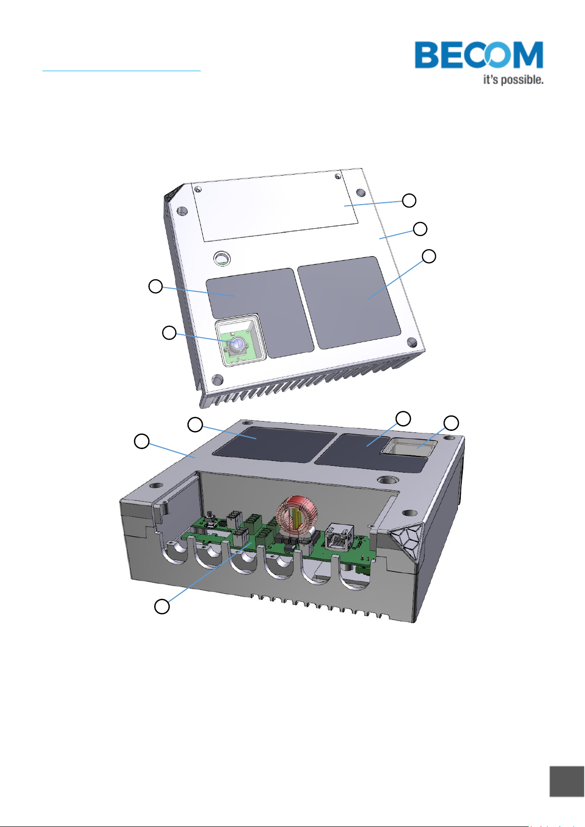
Figure 2-1: Argos3D - P33x components
a. Case
b. Viewing window for 3D sensor
c. Viewing window for 2D sensor (on the Argos3D-P331 the 2D sensor is not present)
d. Viewing window for illumination module
e. Interface cover
f. Interface board
© BECOM Systems 2020
10 | 30
Hardware User Manual - Argos3D - P33x
Last change: 29 June 2020/Version 12
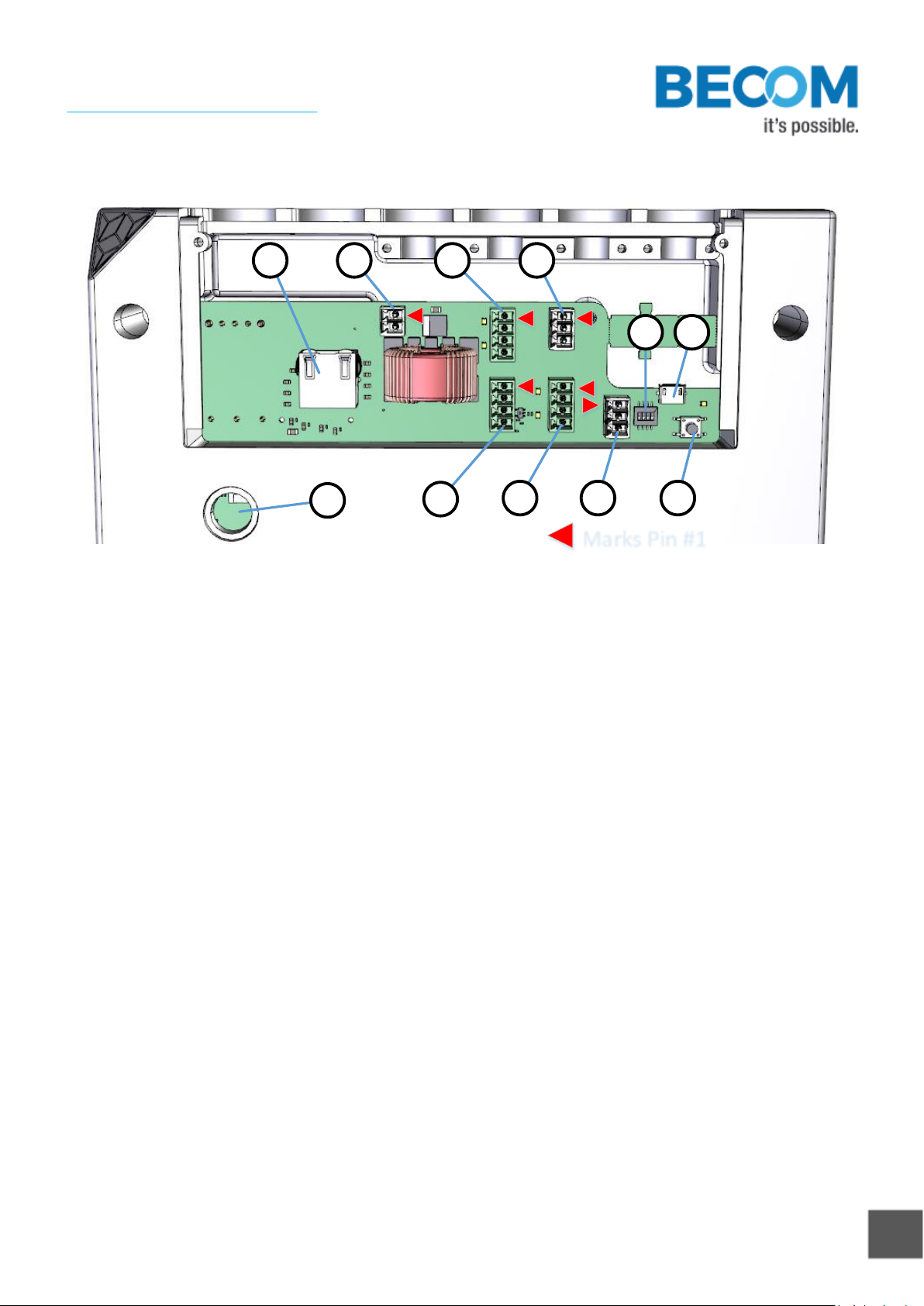
2.2 Interfaces and Connectors
Marks Pin #1
b a c f
ed g i
h j
k
Figure 2-2: Argos3D - P33x connectors and interfaces
a. Power supply
b. Ethernet (RJ45) 10/100/1000Base-T with PoE++. POE is only available on P330 and P331.
c. General purpose inputs, galvanic isolated
d. General purpose outputs, galvanic isolated
e. Modulation Light Interface
f. Trigger
g. RS232/485
h. DIP-Switch
i. Reset-Button
j. Debug-UART
k. Status LED
© BECOM Systems 2020
11 | 30
Hardware User Manual - Argos3D - P33x
Last change: 29 June 2020/Version 12
3Hardware Installation
3.1 Mounting
Caution
Case may become hot!
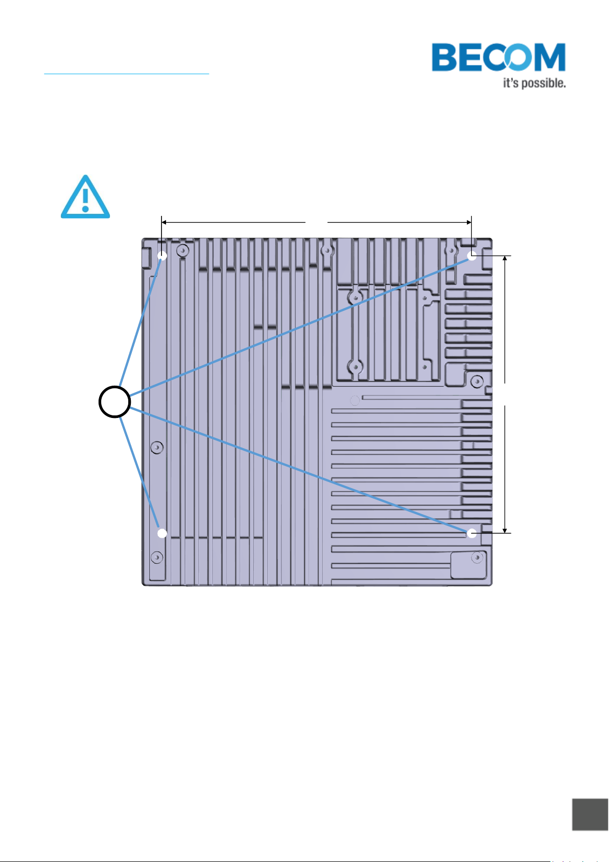
180.0
161.0
a
Figure 3-1: Mounting holes for the case
3.1.1 Mounting Holes (a)
The case has four holes for up to M5 screws that allows mounting the Argos3D - P33x.

© BECOM Systems 2020
12 | 30
Hardware User Manual - Argos3D - P33x
Last change: 29 June 2020/Version 12
3.1.2 Mount Spacing
30
b ac
Figure 3-2: Distance to mounted wall
a. Argos3D - P33x
b. Spacers
c. Wall or mounting panel
To maintain a natural air flow behind the Argos3D - P33x, the device should not be mounted closer than 30 mm to
the mounting panel. A keep-out area of at least 50 mm on the four small sides must be provided as well.
Caution
The user is responsible to take care for a correct mounting and to not exceed the operation
temperatures.

© BECOM Systems 2020
13 | 30
Hardware User Manual - Argos3D - P33x
Last change: 29 June 2020/Version 12
4Interface Description
4.1 Signal naming
Signal names are usually written in capital letters. They are noted in positive logic (positive asserted). If the signal
is negative asserted an “n” will be added as prefix to the signal name.
Type:
The type describes the electrical characteristics of the signal. The following types are available:
•I Input
•O Output
•DN Negative Differential Output
•DP Positive Differential Output
•P Power supply
4.2 Connector Numbering
All pins no. 1 of each connector are marked in the figures with a red arrow. The connector numbering always starts
at this pin, continuing in this row, and going backwards at the opposite side.
4.3 Interface-Slot
Marks Pin #1
b a c f
ed g i
h j
k

© BECOM Systems 2020
14 | 30
Hardware User Manual - Argos3D - P33x
Last change: 29 June 2020/Version 12
Figure 4-1: Argos3D - P33x connector location
a. Power Connector
b. Ethernet
c. General purpose input 1 & 2
d. General purpose output 1 & 2
e. Modulation Light Interface (not supported, please do not use)
f. Trigger
g. RS232 / RS485 (functionality depends on firmware version)
h. DIP-Switch
i. Reset-Button
j. Debug-UART
k. Status LED
4.3.1 Power Connector (a)
This 3.5mm terminal connector allows plugging a cable entry plug like 691361100002 from Würth Elektronik.
Compatible connectors from other manufacturers may be found as well.
No.
Signal
Type
Description
1
VIN
P
Positive power supply
2
GND
P
Power ground
Table 4-1: Power connector description
Voltage range: 18V to 30V.
Note
Use inherently limited power sources only!
4.3.2 Ethernet and PoE (b)
This is a standard straight RJ45 10/100/1000 Base-T compatible Ethernet connector.
The Argos3D-P330 and Argos3D-P331 supports PoE++ as alternative power source. Please use a valid PoE++ (90W)
injector or switch only. Using another PoE standard may cause the camera to be not fully operational. Please
check the status of your PoE connection in the StatusRegister. Please refer to the Software User Manual for
additional information and a register description.
4.3.3 General purpose input 1 & 2 (c)
This 4 pole 3.5mm terminal connector allows plugging a cable entry plug like 691361100004 from Würth Elektronik.

© BECOM Systems 2020
15 | 30
Hardware User Manual - Argos3D - P33x
Last change: 29 June 2020/Version 12
No.
Signal
Type
Description
1
IN2A
I (0V to 50V)
Opto-coupler contact A
2
IN2B
I (0V to 50V)
Opto-coupler contact B
3
IN1A
I (0V to 50V)
Opto-coupler contact A
4
IN1B
I (0V to 50V)
Opto-coupler contact B
Table 4-2: General purpose input 1 & 2 connector description
An optocoupler SFH6286-2T from Vishay is used for each general purpose input.
OFF-Range: 0V to 2V.
ON-Range: 5V to 50V.
4.3.4 General purpose output 1 & 2 (d)
This 4 pole 3.5mm terminal connector allows plugging a cable entry plug like 691361100004 from Würth Elektronik.
No.
Signal
Type
Description
1
OUT1A
SPST-A
Relay contact A
2
OUT1B
SPST-B
Relay contact B
3
OUT2A
SPST-A
Relay contact A
4
OUT2B
SPST-B
Relay contact B
Table 4-3: General purpose output 1 & 2 connector description
A solid state relay ASSR-3210 from Avago Technologies is used for each general purpose output.
Maximum voltage: 250V.
Maximum current: 200mA.
4.3.5 Trigger (f)
This 3 pole, 3.5mm terminal connector allows plugging a cable entry plug like 691361100003 from Würth
Elektronik.

© BECOM Systems 2020
16 | 30
Hardware User Manual - Argos3D - P33x
Last change: 29 June 2020/Version 12
No.
Signal
Type
Description
1
TriggerOUT
O (open drain with internal 1k1) pull-up to 5V)
Trigger Output
2
TriggerIN
I
Max Input Voltage: 20V
Max High Threshold: 3,3V
Min Low Threshold: 0,6V
Trigger Input
3
GND
P
Power ground
Table 4-4: Trigger connector description
Note
The usage of this interface may depend on the firmware version.
1) Depends on camera version. Only valid for version >V1.1.0 (P330, P331) and >V1.0.0 (P332).
Figure 4-2: Example schematic for an external trigger circuit
Figure 4-3: timing diagram of the hardware trigger signal, triggers on rising edge.
4.3.6 RS232/RS485 (g)
This 3 pole 3.5mm terminal connector allows plugging a cable entry plug like 691361100003 from Würth Elektronik.

© BECOM Systems 2020
17 | 30
Hardware User Manual - Argos3D - P33x
Last change: 29 June 2020/Version 12
No.
Signal
Type
Description
1
GND
P
Signal Ground
2
RS232 RxD1)
RS485 A/Y
IO
DN
RS232 Receive Data
RS485 Negative Differential Data
3
RS232 TxD1)
RS485 B/Z
IO
DP
RS232 Transmit Data
RS485 Positive Differential Data
Table 4-5: GPIO Connector Description
1) The interface mode can be selected with the DIP-Switch (see chapter 0).
The RS232 interface is running in full duplex mode and the RS485 is running in half duplex mode.
Note
The usage of this interface may depend on the firmware version.
4.3.7 DIP-Switch (h)
The DIP-Switch allows configuring the RS232/RS485 transceiver. The following table shows the functionality of
each switch.
No.
Name
Description
1
-
Not used
2
-
Not used
3
RS485 Enable
ON: Transceiver works in RS485 mode
OFF: Transceiver works in RS232 mode
4
RS485 Termination
ON: Enables the 120Ω RS485 termination resistor
OFF: No termination resistor is active
Table 4-6: DIP-Switch Description
4.3.8 Reset-Button (i)
This button can be used to perform a hardware reset and a factory default reset.
For further information about the factory default reset function see Software User Manual of the Argos3D - P33x.
4.3.9 Debug-UART (j)
This Micro-USB connector provides a Debug-UART interface to the camera.
Note
Make sure that the termination resistor is always disabled, if the driver runs in RS232 mode.

© BECOM Systems 2020
18 | 30
Hardware User Manual - Argos3D - P33x
Last change: 29 June 2020/Version 12
A FT234 from FTDI is used as UART-to-USB-Converter.
4.3.10 Status LED (k)
The Status LED indicates whether the power supply is within the specified range (green), or not (red). Additional
functionalities may be firmware dependent. Please refer to the Software User Manual for additional information.

© BECOM Systems 2020
19 | 30
Hardware User Manual - Argos3D - P33x
Last change: 29 June 2020/Version 12
5Software
5.1 Firmware
For a description of the firmware related interfaces, protocol descriptions, register settings, etc. please refer to
the Software User Manual.
5.2 Demo Application
For the first evaluation of the camera and to evaluate different settings and configurations a .NET demo
application for Microsoft Windows is provided: BLT-ToF-Suite. The demo application can be downloaded from our
support web site.
Software and documentation
support.systems.becom-group.com
5.3 Getting Started Software Development Example
To facilitate the integration of the Argos module in your own application a getting started example will be
available on our download site. Please refer to our support site.
Software and documentation
support.systems.becom-group.com
5.4 Camera Firmware Development KITs
The camera offers the possibility to bring your own application onto the Argos3D - P33x. Using the quad core
i.MX6 processor from Freescale Inc., one core is reserved for the calculation of the depth data, the other cores can
be used by customers for their own applications.
The Argos3D - P33x is based on an embedded Linux system.

© BECOM Systems 2020
20 | 30
Hardware User Manual - Argos3D - P33x
Last change: 29 June 2020/Version 12
6Appendix
6.1 Operating Conditions
Symbol
Parameter
Min
Typical
Max
Unit
VIN
Input supply voltage
18
24
30
V
IIN
Input current at 24V
1.2 1)
4.3 2)
A
IINT
Input current during integration
5.4
5.5
5.6
A
IIR
Inrush Current
7.3
T
Operating Temperature 3)
0°
50°
°C
T
Storage Temperature
-40
+85
°C
tINT
Integration Time
0
7500
µs
FITP
Frame-rate Integration Time Product
780
IP
Ingression protection
IP41 4)
Table 6-1: Operating Conditions
1) Note
Valid for a typical operation condition: frame-rate of 40fps, an integration time of 1000µs and
24V input voltage supply. The input current depends on the applied frame-rate, integration time
and input supply voltage.
2) Note
At maximum Framerate Integration-Time Product (FITP) of 26 fps and 7500µs tINT.
3) Note
The maximum operating temperature strongly depends on the FITP.
4) Note
In preferred mounting situation
6.1.1 Input current
The input current depends on the selected frame-rate (fps) and the integration time (tINT). The following figure
shows typical values. The values for the x axis shows the FITP which has been calculated with the following
equation:
Other manuals for Argos3D-P33 Series
1
This manual suits for next models
6
Table of contents
Other Becom 3D Camera manuals


