Becom 150-3078-1 User manual

PoE-Splitter
User Manual
Version 3

© BECOM Systems 2021
User Manual - PoE-Splitter
Last change: 25 March 2021/Version 3
2| 15
BECOM Systems GmbH
Gutheil-Schoder-Gasse 17
1230 Wien
AUSTRIA
office.systems@becom-group.com
systems.becom-group.com
PoE-Splitter –User Manual
Publication date: March 25, 2021
Subject to change without notice. Errors excepted.
This document is protected by copyright. All rights reserved. No part of this document may be reproduced or
transmitted for any purpose in any form or by any means, electronically or mechanically, without expressly
written permission by BECOM Systems.
Windows is a registered trademark of Microsoft.

© BECOM Systems 2021
User Manual - PoE-Splitter
Last change: 25 March 2021/Version 3
3| 15
Table of Contents
1General Information ...........................................................................................................................................................................................................5
1.1 Symbols Used.....................................................................................................................................................................................................................5
1.2 Safety instructions ...................................................................................................................................................................................................6
1.3 Electrical connection..............................................................................................................................................................................................6
2Mechanical Installation....................................................................................................................................................................................................7
2.1 Front view .......................................................................................................................................................................................................................7
2.2 Top view ...........................................................................................................................................................................................................................7
2.3 Mounting..........................................................................................................................................................................................................................7
2.3.1 Top Hat Rail Mount........................................................................................................................................................................................... 8
2.3.2 Wall mount.............................................................................................................................................................................................................. 8
3Connecting the Device ....................................................................................................................................................................................................9
3.1.1 Connecting the Camera using a dedicated Camera Cable from BECOM Systems...................................10
4Technical Information ......................................................................................................................................................................................................11
4.1 PoE........................................................................................................................................................................................................................................11
4.2 Operating Conditions ...........................................................................................................................................................................................11
4.3 Product Anomalies .................................................................................................................................................................................................11
5Trouble Shooting.................................................................................................................................................................................................................12
5.1.1 Troubleshooting List.......................................................................................................................................................................................12
5.1.2 Support......................................................................................................................................................................................................................12
6Ordering Information.......................................................................................................................................................................................................13
7Document Revision History........................................................................................................................................................................................14
AList of Figures and Tables ............................................................................................................................................................................................15

© BECOM Systems 2021
User Manual - PoE-Splitter
Last change: 25 March 2021/Version 3
4| 15
© BECOM Systems GmbH 2021
All Rights Reserved.
The information herein is given to describe certain components and shall not be considered as a guarantee of
characteristics.
Terms of delivery and rights of technical change reserved.
We hereby disclaim any warranties, including but not limited to warranties of non-infringement, regarding
circuits, descriptions and charts stated herein.
BECOM Systems makes and you receive no warranties or conditions, express, implied, statutory or in any
communication with you. BECOM Systems specifically disclaims any implied warranty of merchantability or fitness
for a particular purpose.
BECOM Systems takes no liability for any damages and errors causing of the usage of this board. The user of this
board is responsible by himself for the functionality of his application. He is allowed to use the board only if he
has the qualification. More information is found in the General Terms and Conditions (AGB).
Information
For further information on technology, delivery terms and conditions and prices please contact BECOM Systems
www.becom-group.com

© BECOM Systems 2021
User Manual - PoE-Splitter
Last change: 25 March 2021/Version 3
5| 15
1General Information
This guide applies to the PoE-Splitter from BECOM Systems. Follow this guide chapter by chapter to set up and
understand your product. If a section of this document only applies to certain camera parts, this is indicated at
the beginning of the respective section.
The document applies to product V1.0.x
1.1 Symbols Used
This guide makes use of a few symbols and conventions:
Warning
Indicates a situation which, if not avoided, could result in minor or moderate injury and/or
property damage or damage to the device.
Caution
Indicates a situation which, if not avoided, may result in minor damage to the device, in
malfunction of the device or in data loss.
Note
Notes provide information on special issues related to the device or provide information that will
make operation of the device easier.
Procedures
A procedure always starts with a headline
1. The number indicates the step number of a certain procedure you are expected to
follow.
Steps are numbered sequentially.
This sign indicates an expected result of your action.
References
This symbol indicates a cross reference to a different chapter of this manual or
to an external document.

© BECOM Systems 2021
User Manual - PoE-Splitter
Last change: 25 March 2021/Version 3
6| 15
1.2 Safety instructions
Important
This manual is part of the device and contains information and illustrations about the correct
handling of the device and must be read before installation or use. Observe the operating
instructions. Non-observance of the instructions, operation which is not in accordance with use as
prescribed below, wrong installation or handling can affect the safety of people and machinery.
The installation and connection must comply with the applicable national and international
standards. Responsibility lies with the person installing the unit.
1.3 Electrical connection
Note
The unit must be connected by a qualified electrician.
Device of protection class III (PC III).
The electric supply must only be made via PELV circuits.
The device must only be powered by a limited energy source (≤ 30 V; ≤ 8 A; ≤ 100 VA).
Disconnect power before connecting the unit.

© BECOM Systems 2021
User Manual - PoE-Splitter
Last change: 25 March 2021/Version 3
7| 15
2Mechanical Installation
All dimensions are in mm, tolerance +/-0,5mm.
2.1 Front view
30
Figure 2-1: Front view dimensions
2.2 Top view
41,5
91
5,5
118
Top Hat Rail Mount (optional)
Nut for Wall
Mounting
Nut for Wall
Mounting
Figure 2-2: Top view dimensions
2.3 Mounting
There are two mounting possibilities
© BECOM Systems 2021
User Manual - PoE-Splitter
Last change: 25 March 2021/Version 3
8| 15
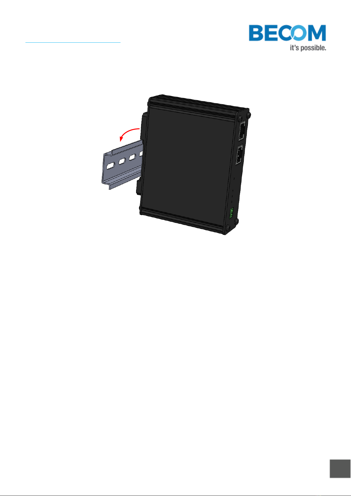
2.3.1 Top Hat Rail Mount
The Rail mount can be used to mount the device on a top hat rail according to IEC/EN 60715.
Figure 2-3: Hat rail mount
2.3.2 Wall mount
Two nuts in the housing can be used for wall mounting the device. Please refer to Figure 2-2 to see the
dimensions and positions of the nuts.
© BECOM Systems 2021
User Manual - PoE-Splitter
Last change: 25 March 2021/Version 3
9| 15
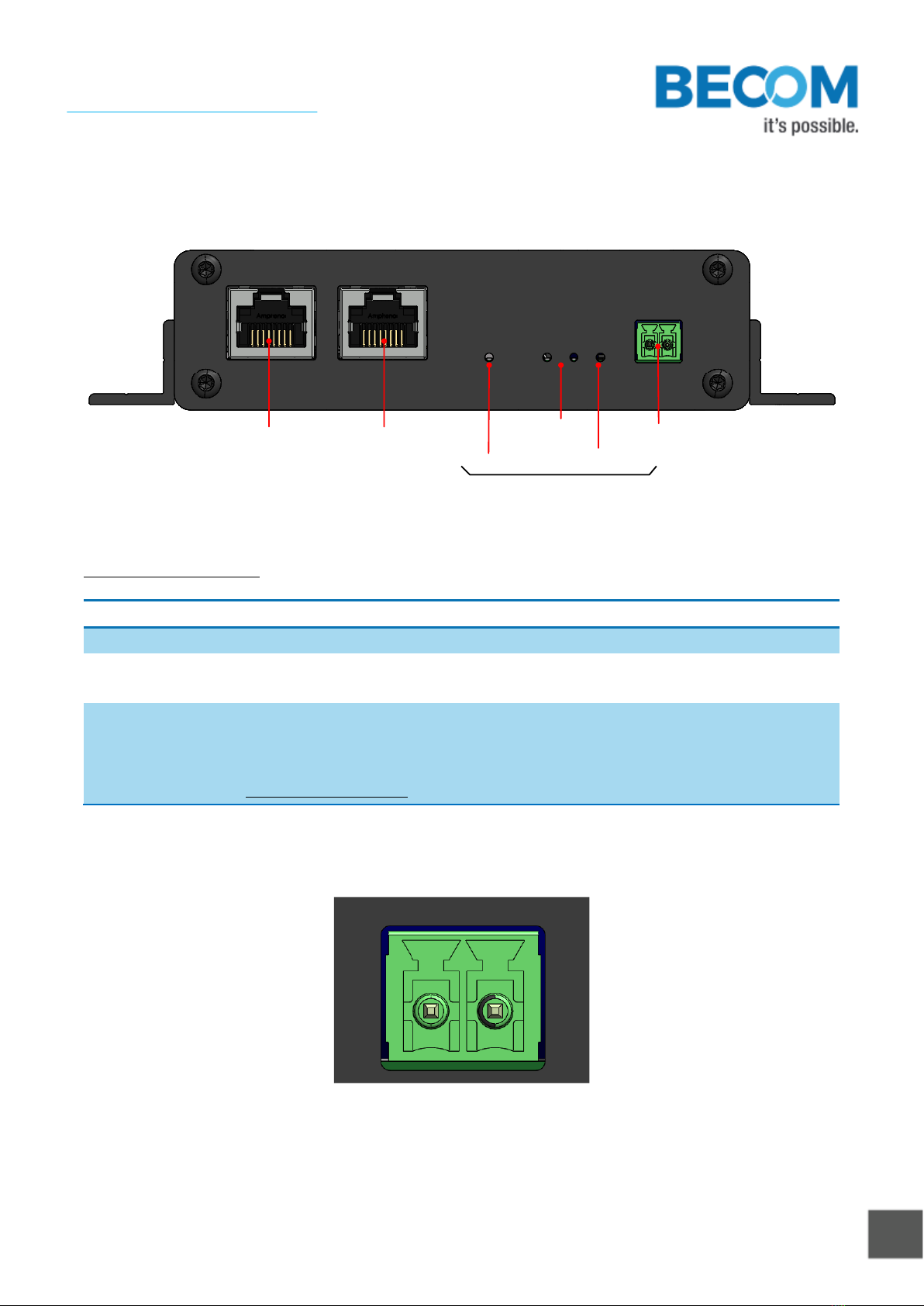
3Connecting the Device
The following figure shows the interfaces and status LEDs of the device.
Data & PoE IN Data OUT
Power Current Limiter
PoE Class 24V DC OUT
Status LEDs
Figure 3-1: Connectors and LEDs
Connector description:
Connector
Description
Data & PoE IN
Connect this to your PoE switch or injector with a CAT5e or higher category patch cable.
Data OUT
Connect this to your camera with a CAT5e or higher category patch cable or connect it
with the RJ45 plug of your dedicated camera cable from BECOM systems.
24V DC OUT
Connect this header to the power supply cable of your camera. Refer to Figure 3-2 for
the pin description or connect it to the dedicated wires of your camera cable from
BECOM Systems using an appropriate mating part.
Mating part suggestion: 691361100002 from Würth Electronics or similar part
Table 3-1: Connector Description
V+V-
Figure 3-2: Pin description of the camera power supply connector (24V DC OUT)

© BECOM Systems 2021
User Manual - PoE-Splitter
Last change: 25 March 2021/Version 3
10 | 15
3.1.1 Connecting the Camera using a dedicated Camera Cable from BECOM Systems
To Switch /
Injector
Argos3D-P2x
cable
Figure 3-3: Example for connecting an Argos3D-P2xx camera to the PoE-Splitter

© BECOM Systems 2021
User Manual - PoE-Splitter
Last change: 25 March 2021/Version 3
11 | 15
4Technical Information
4.1 PoE
The device supports PoE Plus (802.3at)
4.2 Operating Conditions
Symbol
Parameter
Min
Typical
Max
Unit
IAVG
Average input current
Note 1)
A
IPK
Peak input current
Note 2)
A
Top
Operating temperature
-40
+85
°C
Tst
Storage temperature
-40
+105
°C
Table 4-1: Operating Conditions
Note 1)
Depends on the power consumption of the connected camera.
Note 2)
Depends on the connected camera device. The drawn peak current should not exceed the
limit as defined in 802.3 for the negotiated PoE class.
4.3 Product Anomalies
Applies to
Date
Description
V1.0.0
14.09.2020
No anomalies reported yet
Table 4-2: Product anomalies

© BECOM Systems 2021
User Manual - PoE-Splitter
Last change: 25 March 2021/Version 3
12 | 15
5Trouble Shooting
5.1.1 Troubleshooting List
Problem description
Possible reason
Measures
The power LED is not lightning
The PoE-Splitter is not well powered.
Please check the connection to the
PoE switch or injector.
Check if your switch or injector is
powered correctly.
The “Current Limiter” LED is
always flashing
This is an intended behavior. The
PoE-Splitter limits the current to the
allowed current based on the
negotiated PoE class.
No measures are necessary.
Table 5-1: Troubleshooting list
5.1.2 Support
General support for products can be found at BECOM Systems’ support site
Support Link
support.systems.becom-group.com
For further questions please contact our support team at support.systems@becom-group.com.

© BECOM Systems 2021
User Manual - PoE-Splitter
Last change: 25 March 2021/Version 3
13 | 15
6Ordering Information
Product Ordering
Number
Product
Description
150-3078-1
PoE-Splitter
Basic device with different mounting options
Table 6-1: Ordering information

© BECOM Systems 2021
User Manual - PoE-Splitter
Last change: 25 March 2021/Version 3
14 | 15
7Document Revision History
Version
Date
Document Revision
1
14.09.2020
Initial draft
2
03.12.2020
Figures added
3
25.03.2020
Typos corrected
Table 7-1: Document revision history

© BECOM Systems 2021
User Manual - PoE-Splitter
Last change: 25 March 2021/Version 3
15 | 15
AList of Figures and Tables
Figures
Figure 2-1: Front view dimensions..........................................................................................................................................................................................................7
Figure 2-2: Top view dimensions.............................................................................................................................................................................................................7
Figure 2-3: Hat rail mount ............................................................................................................................................................................................................................. 8
Figure 3-1: Connectors and LEDs............................................................................................................................................................................................................. 9
Figure 3-2: Pin description of the camera power supply connector (24V DC OUT) ................................................................................... 9
Figure 3-3: Example for connecting an Argos3D-P2xx camera to the PoE-Splitter .................................................................................. 10
Tables
Table 3-1: Connector Description ........................................................................................................................................................................................................... 9
Table 4-1: Operating Conditions..............................................................................................................................................................................................................11
Table 4-2: Product anomalies....................................................................................................................................................................................................................11
Table 5-1: Troubleshooting list.................................................................................................................................................................................................................12
Table 6-1: Ordering information..............................................................................................................................................................................................................13
Table 7-1: Document revision history................................................................................................................................................................................................ 14
Table of contents
Popular Cables And Connectors manuals by other brands

Comprehensive
Comprehensive CP-HDA2 user manual

Web Warehouse
Web Warehouse WebHeat Frost 1 installation manual

Titanium
Titanium TT-FIL-20/2 quick start guide

ADC
ADC TrueNet Four-Pair Riser Cable Specifications

VOLTCRAFT
VOLTCRAFT DO-10i operating instructions

Kohler
Kohler 12504A-NA installation instructions


