BEFCO CYCLONE SUPER-FLEX series User manual

BEFCO®
Operator’s Manual
CYCLONE SUPER-FLEX
Gang Grooming Mower
412-SFL, 415-SFL, 417-SFL, 420-SFL
The operator’s manual is a technical service guide and must always accompany the machine.
Manual 961-208B
August 2018

SAFETY
Take note! This safety alert symbol found throughout this manual is used to call your
attention to instructions involving your personal safety and the safety of others. Failure to
follow these instructions can result in injury or death.
Signal Words
Note the use of the signal words DANGER, WARNING and CAUTION with the safety messages. The
appropriate signal words for each have been selected using the following guidelines:
DANGER: Indicates an imminently hazardous situation that, if not avoided, will result in death or
serious injury.
WARNING: Indicates a potentially hazardous situation that, if not avoided, could result in death or
serious injury, and includes hazards that are exposed when guards are removed. It may also be used
to alert against unsafe practices.
CAUTION: Indicates a potentially hazardous situation that, if not avoided, may result in minor or
moderate injury.
This symbol means:
ATTENTION!
BECOME ALERT!
YOUR SAFETY IS INVOLVED!

48
8 - WARRANTY
47
7 - PRE-DELIVERY CHECKLIST
45
6 - TROUBLESHOOTING
445.03 - Suggested Spare Parts 435.02 - Blade Spindle 435.01 - Gearbox 43
5 - REPAIR PROCEDURES
414.08 - Storage 404.07 - Transport 394.06 - Drivelines and Center Gearbox Timing 384.05 - Belt Replacement 374.04 - Belt Tension 354.03 - Blade Maintenance 324.02 - Service 314.01 - Maintenance Safety 31
4 - MAINTENANCE
303.13 - Uneven Terrain 283.12 - Operating Techniques 283.11 - Working Speed 263.10 - Start Up 223.09 - Frame Adjustments 213.08 - Hydraulic Lift System 213.07 - Constant Velocity Driveline 193.06 - Attaching to the Tractor 183.05 - Pre-Operational Check 173.04 - Cutting Height Adjustment 153.03 - Light Kit Installation 133.02 - Setup and Assembly Instructions 113.01 - Operational Safety 11
3 - OPERATION
72.03 - Messages and Signs 72.02 - Starting and Stopping 62.01 - Preparation 6
2 - SAFETY PRECAUTIONS
51.03 - Model and Serial Number ID 41.02 - Warranty Information 41.01 - General 4
1 - GENERAL INFORMATION
INDEX
INDEX 3BEFCO

1 - GENERAL INFORMATION
Thank you and congratulations for having chosen our implement. Your new gang
grooming mower is a technologically advanced machine constructed of high quality,
sturdy components that will fulfill your working expectations. Read this manual carefully.
It will instruct you on how to operate and service your mower safely and correctly.
Failure to do so could result in personal injury and/or in equipment damage.
1.01 - General
The implement described in this manual is to be used with tractors with PTO at 540 rpm
and clockwise rotation.
CAUTION: Always ensure that the coupling of the implement with the tractor is
done at the same PTO speed and direction of rotation. Do not operate this
implement at a PTO speed or direction of rotation other than that shown on the
implement. Serious damage can occur to the machine and/or the operator.
CAUTION: Unless otherwise specified, all hardware is metric. Use only metric
tools on metric hardware. Other tools that do not fit properly can slip and cause
injury.
CAUTION: Right hand and left hand sides of the implement are determined by
facing in the direction the implement will travel when going forward (see fig. 2).
1.02 - Warranty Information
Carefully read the Warranty section1, detailing coverage and limitations of this warranty.
Warranty is provided for customers who operate and maintain their equipment as
described in this manual. Warranty registration is accomplished by the dealer by
completing and forwarding the Warranty Registration form to the Company, along with
a copy of the dealer’s invoice. It is in your best interest to insure that this has been
done.
Warranty does not cover the following:
1. Cleaning, transporting, mailing and service call charges.
CYCLONE SUPER-FLEX OPERATOR’SMANUAL
GENERAL INFORMATION 4BEFCO
1See Chapter 8 - Warranty.

2. Normal wear items such as belts, blades, bearings, drivelines, shear pins, slip
clutches, hydraulic hoses and seals, tires, etc.
3. Depreciation or damage caused by normal wear, accidents, improper maintenance,
improper protection or improper use.
4. The use of non-original spare parts and accessories.
Your Authorized Company Dealer has genuine parts in stock. Only these approved
replacement parts should be used.
This limited warranty covers defective material and workmanship. The cost of normal
maintenance or repairs for accidents or improper use and related labor will be borne by
the owner.
1.03 - Model and Serial Number ID
Attached to the frame is an ID plate showing the model and the serial number. Record
your implement model and serial number in the space provided below. Your dealer
needs this information to give you prompt, efficient service when you order parts.
CYCLONE SUPER-FLEX OPERATOR’SMANUAL
GENERAL INFORMATION 5BEFCO

2 - SAFETY PRECAUTIONS
Safety is the primary concern in the design and manufacture of our products.
Unfortunately our efforts to provide safe equipment can be wiped out by a single
careless act of an operator.
In addition to the design and configuration of equipment, hazard control and accident
prevention are dependent upon the awareness, concern, prudence and proper training
of personnel involved in the operation, transport, maintenance and storage of
equipment. It is the operator’s responsibility to read and understand all safety and
operating instructions in the manual and to follow these.
Allow only properly trained personnel to operate the mower. Working with unfamiliar
equipment can lead to careless injuries. Read this manual, and the manual for your
tractor, before assembly or operation, to acquaint yourself with the machines. It is the
mower owner’s responsibility, if this machine is used by any person other than yourself,
is loaned or rented, to make certain that the operator, prior to operating, reads and
understands the operator’s manuals and is instructed in safe and proper use.
2.01 - Preparation
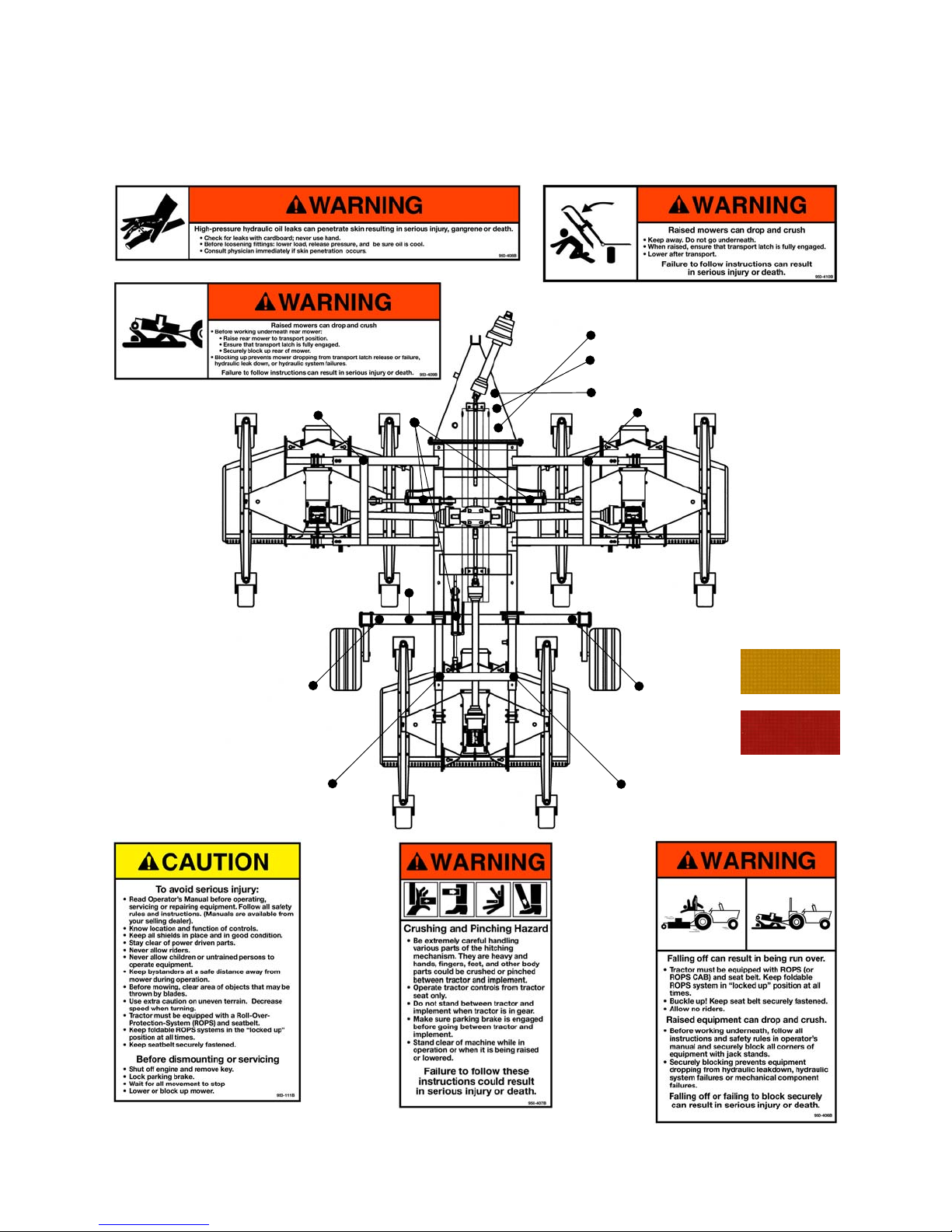
1. Before operating equipment read and understand the operator’s manual and the
safety signs (see fig. 2).
2. Thoroughly inspect the implement before initial operation to assure that all
packaging materials, i.e. wires, bands, and tape have been removed.
3. Personal protection equipment including hard hat, safety glasses, safety shoes, and
gloves are recommended during assembly, installation, operation, adjustment,
maintaining and/or repairing the implement.
4. Operate the mower only with a tractor equipped with an approved
Roll-Over-Protective-System (ROPS). Always wear your seat belt. Serious injury or
even death could result from falling off the tractor.
5. Clear area to be cut of stones, branches or other debris that might be thrown,
causing injury or damage.
6. Operate only in daylight or good artificial light.
7. Ensure mower is properly mounted, adjusted and in good operating condition.
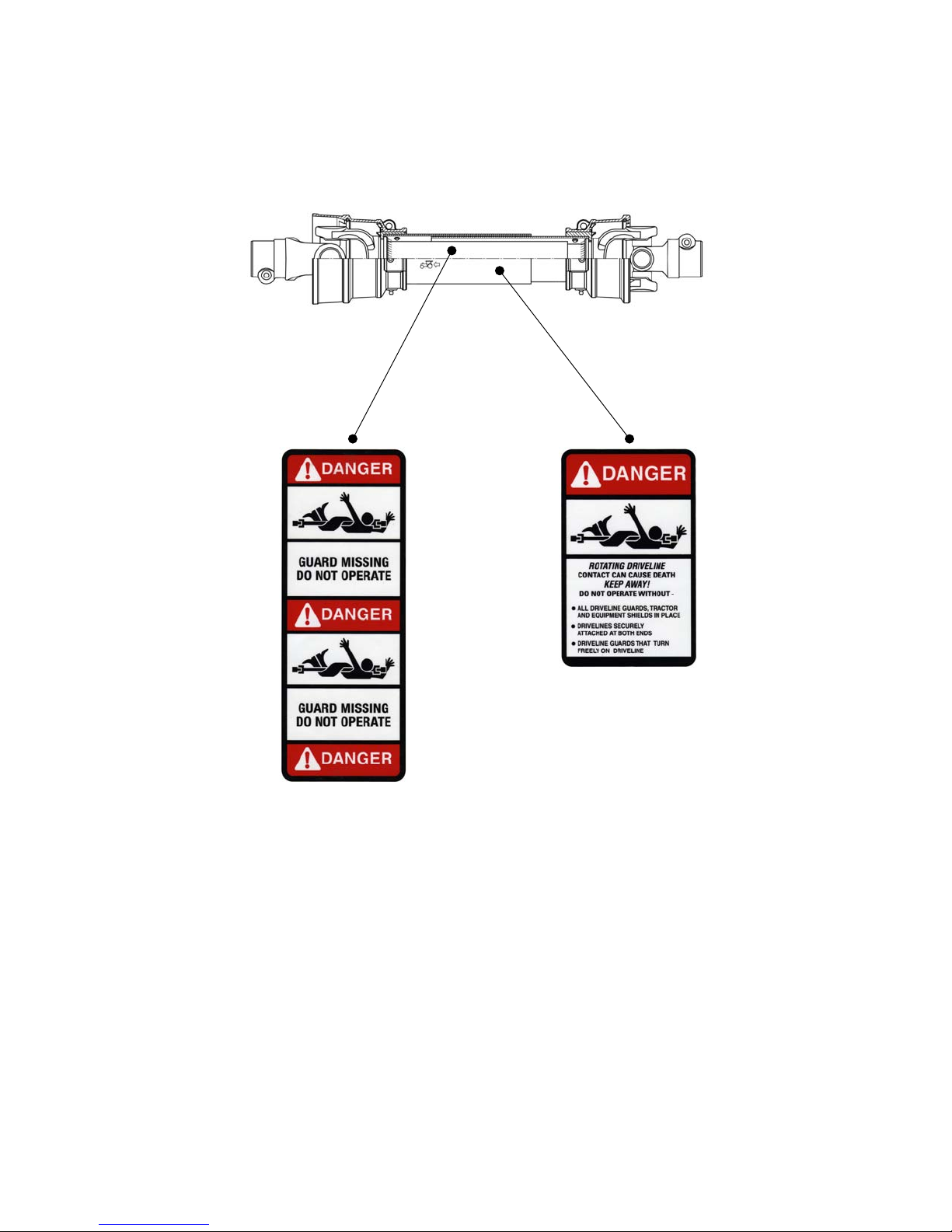
8. Ensure that all safety shielding and safety signs are properly installed and in good
condition.
SAFETY PRECAUTIONS 6BEFCO
CYCLONE SUPER-FLEX OPERATOR’SMANUAL

2.02 - Starting and Stopping
1. Be sure that no one is near the machine prior to engaging or while the machine is
working.
2. Be sure the tractor is in “Neutral” before starting engine.
3. Mower operating power is supplied from tractor PTO. Refer to your tractor manual
for PTO engagement and disengagement instructions. Always operate PTO at 540
rpm. Know how to stop the tractor and mower quickly in case of an emergency.
4. When engaging PTO, the engine rpm should always be low. Once engaged and
ready to start cutting, raise PTO speed to 540 rpm and maintain throughout cutting
operation.
5. Check the tractor master shield over the PTO stub shaft. Make sure it is in good
condition and fastened securely to the tractor. Purchase a new shield if old shield is
damaged or missing.
6. After striking an obstacle, disengage the PTO, shut the tractor down and thoroughly
inspect for damage before restarting.
7. Never engage the PTO until the mower is in the down position and resting on the
ground. Never raise the mower until all blades have come to a complete stop.
8. To park the vehicle safely, stop vehicle on a level surface (not on a slope),
disengage PTO, engage the parking brake, stop the engine, remove the key, and
wait for engine and all moving parts to stop before leaving the operator’s seat.
9. Stay clear of rotating drivelines. Entanglement in rotating driveline can cause serious
injury or death. Wear close fitting clothing. Stop the engine and be sure PTO
driveline is stopped before getting near it.
2.03 - Messages and Signs
1. Read and adhere to all safety and operating decals on this machine (see fig. 2).
2. Before dismounting tractor: Allow moving parts to stop, stop engine, set brake and
remove the key of unattended equipment.
3. Keep away from rotating blades and driveline.
4. Keep guards and shields in place and in good condition.
5. Do not mow with bystanders in area.
6. Allow no riders on tractor or mower.
7. Allow moving parts to stop before repair.
8. Securely support mower before working underneath.
9. Lock up raised wings before transport (see fig. 13).
Additional warning and operating decals are available at no extra charge. Please specify
model and serial number when ordering.
SAFETY PRECAUTIONS 7BEFCO
CYCLONE SUPER-FLEX OPERATOR’SMANUAL

Fig. 2 - Safety decals, main frame; replace immediately if damaged.
SAFETY PRECAUTIONS 8BEFCO
CYCLONE SUPER-FLEX OPERATOR’SMANUAL
right side
left side
1
3
2
456
7
8
8
8
7
1
33
22
4
5
6
Yellow reflective deca
l
Red reflective decal

Safety decals, decks; replace immediately if damaged.
SAFETY PRECAUTIONS 9BEFCO
CYCLONE SUPER-FLEX OPERATOR’SMANUAL
placed under belt shieldsplaced under belt shields

Safety decals, drivelines; replace immediately if damaged.
SAFETY PRECAUTIONS 10 BEFCO
CYCLONE SUPER-FLEX OPERATOR’SMANUAL
placed on outer shield
placed on outer tube

3 - OPERATION
The Cyclone Super-Flex represents the most advanced proposal for reducing labor cost
without sacrificing quality of cut. The high cutting speed of 8-10 mph along with the wide
working widths of up to 20’, allows for a reduction in man-hours and lower fuel cost for
the maintenance of large grass areas such as sport fields, parks, golf courses and sod
farms.
The Cyclone Super-Flex consists of a frame-carrier, mechanically connecting a trio of
C50 rear discharge grooming mowers. The Cyclone Super-Flex can be used on tractors
with horsepower ranging from 35 to 80. The tractor PTO is connected, through a wide
angle driveline, to a 4 way splitter gearbox. The side and rear output shafts transfer
power to the individual speed multiplier gearboxes on each mower.
The 12’ model consists of two 4’ wing units and one 5’ rear unit, the 15’ model consists
of two 5’ wing units and one 6’ rear unit, the 17’ model consists of three 6’ decks and
the 20’ model consists of three 7’ decks.
Each individual mower works completely independent from the others. They are
connected to the frame by floating arms. All mowers have four wheels allowing free
floating over uneven terrain. Even over rolling ground, the cut is accurate and uniform.
After mowing, during transport and for storage or maintenance, all three mowers can be
raised up hydraulically to a vertical position. During transport or maintenance
operations, it is imperative to be sure the wing mowers are locked in place with the
automatic locking system. To transport over extended distances, the wings should be
locked in their 90 degree vertical position with the transport locks and the metal
transport braces added to the two wing units for added safety. The two transport wheels
allow the Cyclone Flex mower, in its closed and locked position, to be transported safely
on lawns or private roads. The tires are not suitable for extended road travel.
The decks can be raised for easy cleaning and quick blade changes. Top grease fittings
make the greasing of hubs and spindles simple and quick.
3.01 - Operational Safety
CAUTION: Our mowers are designed considering safety as the most important
aspect and are the safest available in today’s market. Unfortunately, human
carelessness can override the safety features built into our machines. Injury
prevention and work safety, aside from the features on our mowers, are very
much due to the responsible use of the equipment. It must always be operated
prudently following with great care, the safety instructions laid out in this manual.
OPERATION 11 BEFCO
CYCLONE SUPER-FLEX OPERATOR’SMANUAL

1. The use of this equipment is subject to certain hazards which cannot be prevented
by mechanical means or product design. All operators of this equipment must read
and understand this entire manual, paying particular attention to safety and
operating instructions, prior to using.
2. Do not operate the tractor and mower when you are tired, sick or when using
medication.
3. Keep all helpers and bystanders at least 300 feet from a rotary mower. Only properly
trained people should operate this machine.
4. When this machine is operated in populated areas where thrown objects could injure
persons or property, standard equipment safety chain shielding (which is designed
to reduce the possibility of thrown objects) must be installed.
5. The majority of accidents involve entanglements on the driveline, injury of
bystanders by objects thrown by the rotating blades, and operators being knocked
off the tractor by low hanging limbs and then being run over by the mower. Accidents
are most likely to occur with machines that are loaned or rented to someone who
has not read the operator’s manual and is not familiar with a rotary mower.
6. Always stop the tractor, set brake, shut off the tractor engine, remove the ignition
key, lower implement to the ground and allow mower blades to come to a complete
stop before dismounting tractor. Never leave equipment unattended with the tractor
running.
7. Never place hands or feet under mower with tractor engine running or before you
are sure all motion has stopped. Stay clear of all moving parts.
8. Do not allow riders on the mower or tractor at any time. There is no safe place for
riders.
9. Do not operate unless all personnel, livestock and pets are at least 300 feet away to
prevent injury by thrown objects.
10.Before backing up, disengage the mower and look behind carefully.
11.Install and secure all guards and shields before starting or operating.
12.Keep hands, feet, hair and clothing away from moving parts.
13.This rotary mower is designed for use only on tractors with 540 rpm power take off.
14.Never operate tractor and mower under trees with low hanging limbs. Operators can
be knocked off the tractor and then run over by the rotating blades.
15.The rotating parts of this machine have been designed and tested for rugged use.
However, they could fail upon impact with heavy, solid objects such as steel guard
rails and concrete abutments. Such impact could cause the broken objects to be
thrown outward at very high velocities. To reduce the possibility of property damage,
serious injury, or even death, never allow the cutting blades to contact such
obstacles.
16.Frequently check mower blades. They should be sharp, free of nicks and cracks and
securely fastened.
17.Stop mower immediately upon striking an obstruction. Turn engine off, remove key,
inspect and repair any damage before resuming operation.
18.Stay alert for holes, rocks and roots in the terrain and other hidden hazards. Keep
away from drop-offs.
OPERATION 12 BEFCO
CYCLONE SUPER-FLEX OPERATOR’SMANUAL

19.Use extreme care and maintain minimum ground speed when transporting on
hillside, over rough ground and when operating close to ditches or fences. Be careful
when turning sharp corners.
20.Reduce speed on slopes and sharp turns to minimize tipping or loss of control. Be
careful when changing directions on slopes. Do not start or stop suddenly on slopes.
Avoid operation on steep slopes.
21.When using a unit, a minimum 20% of tractor and equipment weight must be on
tractor front wheels. Without this weight, tractor could tip over, causing personal
injury or death. The weight may be attained with a front end loader, front wheel
weights, ballast in tires or front tractor weights. When attaining a minimum 20% of
tractor and equipment weight on the front wheels, you must not exceed the ROPS
weight certification. Weigh the tractor and equipment. Do not guess or estimate!
22.Inspect the entire machine periodically2. Look for loose fasteners, worn or broken
parts, and leaky or loose fittings.
23.Use only the driveline supplied with the mower. Do not use it if it is missing any
shield or safety protection.
24.Pass diagonally through sharp dips and avoid sharp drops to prevent “hanging up”
tractor and mower.
25.Avoid sudden starts and stops while traveling up or downhill.
26.Always cut down slopes; never across the face. Avoid operation on steep slopes.
Slow down on sharp turns and slopes to prevent tipping and/or loss of control.
3.02 - Setup and Assembly Instructions
Notice to dealer: Pre-delivery setup and service including lubrication is the
responsibility of the authorized dealer. It is up to him to assure that the machine is in
perfect condition and ready to be used. It is his responsibility to ensure that the
customer is aware of all safety aspects and operational procedures for the mower. He
must also fill out the Pre-Delivery Checklist3prior to delivering the mower.
At times, due to loading restraints the mower is shipped either with the three decks
separate from the frame or fully assembled but with the transport tires and the
telescopic wing arms retracted. It is the dealer’s responsibility to extend transport
tires and telescopic wing arms to proper operating width and to ensure final
assembly of the mower.
CAUTION: Stand clear of bands when cutting as they could be under sufficient
tension to cause them to fly loose. Take care in removing bands and wire, they
often have extremely sharp edges and cut very easily.
To hook the three mowers to the central frame, do the following:
1. Position the decks complete with hitches (see #8, fig. 3) near the telescopic wing
arms (see #1, fig. 3) which are bolted into the lift arms.
OPERATION 13 BEFCO
CYCLONE SUPER-FLEX OPERATOR’SMANUAL
3See Chapter 7 - Pre-Delivery Checklist.
2See Chapter 4 - Maintenance.

2. Insert the attaching pin (see #7, fig. 3) into the tube welded to the hitch (see #9, fig.
3). Place the shim washers (see #5, fig. 3) on either end of the attaching pin.
3. Place the two formed plates (see #3, fig. 3) on either end of the attaching pin (see
#7, fig. 3) with the bend facing outward.
4. With the wing arms down level with the mower decks, position the telescopic wing
arms (see #1, fig. 3) between the two formed plates (see #3, fig. 3). Attach them to
the bolts (see #10, fig. 3) provided.
5. Tighten the nuts (see #4, fig. 3) and bolts (see #10, fig. 3). Ensure after tightening
that the formed plates (see #3, fig. 3) move freely up and down over the attaching
pin (see #7, fig. 3).
6. Using the grease fitting on the hitch (see #6, fig. 3), grease the attaching pin and
formed plate.
OPERATION 14 BEFCO
CYCLONE SUPER-FLEX OPERATOR’SMANUAL
Fig. 3 - Mowing unit assembly.

3.03 - Light Kit Installation
The light kit is an optional kit that can be purchased that contains two light assemblies,
two mounting brackets and wiring harness.
To install the light kit do the following:
1. Remove light assemblies, light mounting brackets, wiring and cable loom from
packaging.
2. Support the rear frame on the side that you are working on. Loosen but do not
remove the bottom set of nuts on rear wheel support. Remove the top nuts leaving
bolts in place (see #4, fig. 4). Slide rear wheel support into operating position. Slide
the light bracket (see #7, fig. 4) over the top rear wheel bolts, replace nuts and
tighten. Note that there is a right and a left bracket.
3. Attach the light assembly to the light bracket using M6x25 hex head bolts and M6
elastic stop nuts supplied in the kit (see #5 & 6, fig. 4). The light wiring harness is
routed through the slot at the end of the light assembly. Repeat steps 2 and 3 for the
opposite side of the mower. Note: The amber lens (see #3, fig. 4) are always to the
outside of the mower frame and the red lens (see #2, fig. 4) to the inside (facing the
rear of the mower frame).
4. Remove from the mower frame the front input shaft protection, the center shaft
protection and the rear shaft protection. Lay wiring harness on a flat surface. Notice
that the wiring harness splits off into a right and a left section. These wires are
labeled respectively “R” and “L”. Cut the smaller 3/8” wire loom in half. Working from
the light connector, insert the left wiring into one piece of wire loom and the right
wiring into the other (see fig. 5).
OPERATION 15 BEFCO
CYCLONE SUPER-FLEX OPERATOR’SMANUAL
Fig. 4 - Light brackets assembly (left rear view).
1
2
3
1. rear wheel support
2. red light
3. amber light
4
5
6
4. nut PT M14
5. bolt HH M6x25
6. nut ES M6
7
7. left light bracket
8
8. light connector

5. Starting at the tractor connector, insert the wiring harness into the large 3/4” wire
loom. Slide the large 3/4” wire loom over the two smaller 3/8” pieces of wire loom
approximately 1”-2”. Secure with a cable tie (see fig. 5). Note: The wiring harness to
the tractor may be longer than necessary and can be shortened and rewired to the
tractor connector if needed.
6. The hydraulic supply line to the rear cylinder is routed through the right square tube
located underneath the front input shaft support. The light kit wiring is routed through
OPERATION 16 BEFCO
CYCLONE SUPER-FLEX OPERATOR’SMANUAL
Fig. 5 - Light kit layout.
cable tie
cable tie
cable tie
hydraulic cross
front input shaft support
hydraulic hose
light kit harness
wire loom 3/8"
cable tie
wire loom 3/4"
slide plug end under
light mount plate
route wiring harness
behind mower plate

the left square tube of the input shaft support. Place a cable tie around the hydraulic
cross and light wiring harness but do not tighten at this time (see fig. 5).
7. Route the right and left light wiring harness alongside the hydraulic hose that
attaches to the rear cylinder (this hose is normally routed under the shaft protection
shields and located on the left side of the mower frame). At the rear of the mower
frame split off the right and left wiring. Route wiring along frame and plug wiring
harness into light plugs (see #8, fig. 4). Place cable ties as shown in the illustration
(see fig. 5) but do not tighten. Note: Because the rear wheel supports can be
adjusted in and out, be sure to leave extra wire to the light assemblies.
8. Wiring harness and hydraulic hoses should be clear of any moving parts. Once
wiring harness is in place, tighten cable ties and cut off excess. Plug in light
connector to the tractor to check light operation.
9. Replace all shields before operating the mower.
3.04 - Cutting Height Adjustment
WARNING: Keep hands and feet away from moving blades.
Be sure the tractor engine is off, parking brake is locked, and key is removed
before making any adjustments.
Never rely on the hydraulic system to hold the weight of the raised mowers.
Never walk or work under the raised mowers without first making sure the
automatic locking system is securely holding the wing units with the hydraulic
cylinders closed, and the hook is engaged to support the rear deck.
OPERATION 17 BEFCO
CYCLONE SUPER-FLEX OPERATOR’SMANUAL
Fig. 6
The cutting height is
adjusted by moving
the height adjustment
spacers on the wheel
yokes above or below
the wheel arm.

The cutting height is the distance from the blades to the ground. The cutting height is
adjusted by moving the height adjustment spacers on the wheel yokes above or
below the wheel arm. Placing spacers between the wheel arm and the wheel yoke
raises the cutting height by the size of the spacer. Removing the spacers lowers it by
the same height (see fig. 6). All the wheel yokes are supplied with three different size
height adjustment spacers, ¼”, ½” and 1”.
Be sure all 12 wheels of the mowers are adjusted equally. This is the only way to
ensure a completely uniform cut.
IMPORTANT: Very low cutting heights should be avoided. Damaging shock loads
occur when the blades strike the ground repeatedly. This can cause damage to
the mower.
Cutting lower than 2” under most circumstances should be avoided.
The cutting height is adjustable from 1” to 5”.
Anti-scalping rollers come standard on each deck for uneven ground contours. The
roller rides the nose of the mower deck over a mound to help keep the nose from
bulldozing or the blade from scalping the ground. The roller is extremely helpful when
mowing particularly low.
3.05 - Pre-Operational Check
IMPORTANT: Check each of the following, carefully, prior to engaging the equipment:
1. The spindle bearings have been greased.
2. The belts for proper tension.
3. The oil level in all gearboxes. Using a flashlight, check inside each one of the
gearboxes to verify that they are approximately half full.
4. The drivelines cross and bearings have been greased.
5. All wheels are fully greased.
6. All grease points on Flex frame have been greased4.
7. No wrappings or foreign objects are around the blades, belts or drivelines.
8. The blades are properly installed and the blade bolts properly torqued5.
9. All hardware is tight.
10.The tractor, to ensure correct direction of PTO and rpm speed.
11.All safety shields and guards are in place and tightly attached.
12.No people or animals are in the work area.
13.The Flex frame is level to ensure its full floating capability.
DANGER: Stay clear of rotating driveline. Entanglement in rotating driveline can
cause serious injury. Disengage PTO, engage parking brake or place
transmission in “Park”, shut off the tractor and remove the key before working
OPERATION 18 BEFCO
CYCLONE SUPER-FLEX OPERATOR’SMANUAL
5See Table 1, page 42.
4See Section 4.02 - Service.

around hitch, attaching or detaching driveline, making adjustments, servicing or
cleaning the machine.
3.06 - Attaching to the Tractor
The Cyclone Super-Flex may be used on any 540 rpm tractor with a drawbar hitch and
horsepower ranging from 35 to 806.
CAUTION: Check the tractor PTO rpm to ensure it is set at 540 rpm and turns
clockwise.
Always ensure that the tractor tire pressure is correct according to the tractor
operator’s manual.
To attach the mower to the tractor do the following:
1. Remove transport brace if it is installed.
2. Back the tractor up to the mower in order to slip the tractor drawbar hitch into the
adjustable hitch bracket. The hitch bracket is adjustable in 3 different positions to
conform to the tractor drawbar height. It may also be turned over for an additional 3
positions (see fig. 7). This is an important feature that permits the leveling of the
Flex frame. Be sure the pin you use can securely attach the mower to the tractor
OPERATION 19 BEFCO
CYCLONE SUPER-FLEX OPERATOR’SMANUAL
6See Table 2, page 42.
Fig. 7
Tongue height
may be adjusted
in 6 different
positions to
ensure a level
frame on any
tractor drawbar.

drawbar7. Turn off the tractor engine. Secure the frame hitch to the tractor drawbar
with the pin. Failure to ensure a secure coupling of the implement to the tractor
can cause injury and damage to the implement or tractor.
3. Lower jack stand until the weight of the mower is on the tractor drawbar. Turn the
jack stand 90 degrees and pin into a horizontal position. For further safety, the jack
stand may also be removed and mounted on the storage area on the tongue.
4. Hook the hydraulic hose to the tractor remote port. Engage the tractor hydraulics to
raise all three mowers. Never use hydraulics without the restrictors installed. Do
not stand or allow anyone to stand under any of the three mowers while
continuing the following instructions.
5. Lower the three mowers8.
6. Install the Constant Velocity driveline, only after ensuring it is the proper length9. The
CV end of the driveline is mounted on the tractor PTO.
7. Check the frame to ensure it is level10.
8. Engage the tractor PTO. It is very important to feather in the PTO.
DANGER: Never engage the PTO until all three mowers are in the down position
and resting on the ground. Never raise the mowers until all three deck blades
have come to a complete stop. Doing so will cause damage to the driveline yokes
and/or cross and bearings and can create a situation which endangers the
operator or bystanders.
OPERATION 20 BEFCO
CYCLONE SUPER-FLEX OPERATOR’SMANUAL
10 See Section 3.09 - Frame Adjustments.
9See Section 3.07 - Constant Velocity Driveline.
8See Raising the Mower Decks and the Automatic Lock Up System in Section 3.09.
7Optional equipment includes a floating hitch for undulating terrain (see fig. 8).
Fig. 8 - Optional floating hitch.
This manual suits for next models
4
Table of contents
Other BEFCO Lawn Mower manuals
Popular Lawn Mower manuals by other brands

BOB-CAT
BOB-CAT 912480 Operator's manual

Craftsman
Craftsman 917.376650 owner's manual

Robust
Robust RB-EM 1030 Original operating instructions

Craftsman
Craftsman EZ3 917.387160 owner's manual

Stiga
Stiga Aero 132e Operator's manual

Alamo Industrial
Alamo Industrial Machete T 7740 Information & Service bulletin