BEFCO CYCLONE User manual

BEFCO®
Operator’s Manual
CYCLONE
Engine Driven Grooming Mower
C30-CE5H
(serial #345293 & above)
The operator’s manual is a technical service guide and must always accompany the machine.
Manual 960-395B
January 2021

SAFETY
Take note! This safety alert symbol found throughout this manual is used to call your
attention to instructions involving your personal safety and the safety of others. Failure to
follow these instructions can result in injury or death.
Signal Words
Note the use of the signal words DANGER, WARNING and CAUTION with the safety messages. The
appropriate signal words for each have been selected using the following guidelines:
DANGER: Indicates an imminently hazardous situation that, if not avoided, will result in death or
serious injury.
WARNING: Indicates a potentially hazardous situation that, if not avoided, could result in death or
serious injury, and includes hazards that are exposed when guards are removed. It may also be used
to alert against unsafe practices.
CAUTION: Indicates a potentially hazardous situation that, if not avoided, may result in minor or
moderate injury.
This symbol means:
ATTENTION!
BECOME ALERT!
YOUR SAFETY IS INVOLVED!

38
PARTS MANUAL
34
8 - WARRANTY
33
7 - PRE-DELIVERY CHECKLIST
31
6 - TROUBLESHOOTING
305.03 - Storage 305.02 - Suggested Spare Parts 305.01 - Blade Spindle 30
5 - REPAIR PROCEDURES
284.05 - Belts Replacement 264.04 - Belt Tension 244.03 - Blade Maintenance 234.02 - Service 224.01 - Maintenance Safety 22
4 - MAINTENANCE
213.12 - Transport 203.11 - Uneven Terrain 193.10 - Operating Techniques 193.09 - Working Speed 173.08 - Start Up 163.07 - Offsetting the Mower 143.06 - Attaching to the Vehicle 143.05 - Pre-Operational Check 123.04 - Cutting Height Adjustment 113.03 - Assembly Instructions 113.02 - Set Up 93.01 - Operational Safety 9
3 - OPERATION
72.03 - Messages and Signs 72.02 - Starting and Stopping 62.01 - Preparation 6
2 - SAFETY PRECAUTIONS
51.03 - Model and Serial Number ID 41.02 - Warranty Information 41.01 - General 4
1 - GENERAL INFORMATION
INDEX
INDEX 3BEFCO

1 - GENERAL INFORMATION
Thank you and congratulations for having chosen our implement. Your new grooming
mower is a technologically advanced machine constructed of high quality, sturdy
components that will fulfill your working expectations. Read this manual carefully. It will
instruct you on how to operate and service your mower safely and correctly. Failure to
do so could result in personal injury and/or in equipment damage.
1.01 - General
CAUTION: Unless otherwise specified, all hardware is metric. Use only metric
tools on metric hardware. Other tools that do not fit properly can slip and cause
injury.
CAUTION: Right hand and left hand sides of the implement are determined by
facing in the direction the implement will travel when going forward (see fig. 2).
1.02 - Warranty Information
Carefully read the Warranty section1, detailing coverage and limitations of this warranty.
Warranty is provided for customers who operate and maintain their equipment as
described in this manual. Warranty registration is accomplished by the dealer by
completing and forwarding the Warranty Registration form to the Company, along with
a copy of the dealer’s invoice. It is in your best interest to insure that this has been
done.
Warranty does not cover the following:
1. Cleaning, transporting, mailing and service call charges.
2. Engine.
3. Normal wear items such as belts, blades, bearings, etc.
4. Depreciation or damage caused by normal wear, accidents, improper maintenance,
improper protection or improper use.
5. The use of non-original spare parts and accessories.
CYCLONE OPERATOR’SMANUAL
GENERAL INFORMATION 4BEFCO
1See Chapter 8 - Warranty.

Your Authorized Company Dealer has genuine parts in stock. Only these approved
replacement parts should be used.
This limited warranty covers defective material and workmanship. The cost of normal
maintenance or repairs for accidents or improper use and related labor will be borne by
the owner.
NOTE: Engine warranty, service and parts must be obtained through an
authorized service center for Briggs & Stratton engines.
1.03 - Model and Serial Number ID
Attached to the frame is an ID plate showing the model and the serial number. Record
your implement model and serial number in the space provided below. Your dealer
needs this information to give you prompt, efficient service when you order parts.
CYCLONE OPERATOR’SMANUAL
GENERAL INFORMATION 5BEFCO

2 - SAFETY PRECAUTIONS
Safety is the primary concern in the design and manufacture of our products.
Unfortunately our efforts to provide safe equipment can be wiped out by a single
careless act of an operator.
In addition to the design and configuration of equipment, hazard control and accident
prevention are dependent upon the awareness, concern, prudence and proper training
of personnel involved in the operation, transport, maintenance and storage of
equipment. It is the operator’s responsibility to read and understand all safety and
operating instructions in the manual and to follow these.
Allow only properly trained personnel to operate the mower. Working with unfamiliar
equipment can lead to careless injuries. Read this manual, the engine manual and the
manual for your tractor, before assembly or operation, to acquaint yourself with the
machines. It is the mower owner’s responsibility, if this machine is used by any person
other than yourself, is loaned or rented, to make certain that the operator, prior to
operating, reads and understands the operator’s manuals and is instructed in safe and
proper use.
2.01 - Preparation
1. Before operating equipment read and understand the operator’s manual and the
safety signs (see fig. 2).
2. Thoroughly inspect the implement before initial operation to assure that all
packaging materials, i.e. wires, bands, and tape have been removed.
3. Personal protection equipment including hard hat, safety glasses, safety shoes, and
gloves are recommended during assembly, installation, operation, adjustment,
maintaining and/or repairing the implement.
4. Operate the mower only with a towing vehicle equipped with an approved
Roll-Over-Protective-System (ROPS). Always wear your seat belt. Serious injury or
even death could result from falling off the vehicle.
5. Clear area to be cut of stones, branches or other debris that might be thrown,
causing injury or damage.
6. Operate only in daylight or good artificial light.
7. Ensure mower is properly mounted, adjusted and in good operating condition.
8. Ensure that all safety shielding and safety signs are properly installed and in good
condition.
9. Use only approved drawbar hitch points.
10.Handle gasoline with care, it is highly flammable. Use only approved gasoline
containers.
11.Never remove fuel cap or add gasoline to a running engine or a hot engine. Never fill
the fuel tank indoors. If spilling occurs wipe up immediately.
SAFETY PRECAUTIONS 6BEFCO
CYCLONE OPERATOR’SMANUAL

12.To reduce fire hazard, keep engine free of grass, leaves or excessive grease.
13.Do not change the engine governor settings or over-speed the engine.
2.02 - Starting and Stopping
1. Be sure that no one is near the machine prior to engaging or while the machine is
working.
2. Be sure the towing vehicle is in “Neutral” before starting engine.
3. Mower operating power is supplied from mower engine. Refer to your engine manual
for engagement and disengagement instructions. Know how to stop the towing
vehicle and mower quickly in case of an emergency.
4. Open doors if engine is running in the garage; exhaust fumes are dangerous. Do not
run engine indoors.
5. After striking an obstacle, stop mower engine, remove the wire from the spark plug,
shut the towing vehicle down and thoroughly inspect for damage before restarting.
6. Do not operate if mower vibrates excessively. Excessive vibration is an indication of
damage.
7. Stop mower engine before backing up. Do not cut in reverse. Carefully observe area
behind mower before backing up.
8. Stop mower engine and watch out for traffic when crossing gravel drives, walks or
roads.
9. Stop mower engine, towing vehicle engine and set parking brake before leaving
operator’s position.
10.Stop mower engine, towing vehicle engine, disconnect spark plug wire, set parking
brake and wait for all movement to stop before making any repairs or adjustments.
11.Never adjust cutting height or leveling linkage while the engine is running.
12.Stop mower engine when transporting or not in use.
13.When leaving towing vehicle unattended, set parking brake, stop both engines and
remove key.
14.Never store the equipment with gasoline in the tank inside a building where fumes
may reach an open flame or spark. Allow engine to cool before storing in any
enclosure.
2.03 - Messages and Signs
1. Read and adhere to all safety and operating decals on this machine (see fig. 2).
2. Before dismounting towing vehicle: allow moving parts to stop, stop both engines,
set brake and remove the key of unattended equipment.
3. Keep away from rotating blades.
4. Keep guards and shields in place and in good condition.
SAFETY PRECAUTIONS 7BEFCO
CYCLONE OPERATOR’SMANUAL

5. Do not mow with bystanders in area.
6. Allow no riders on towing vehicle or mower.
7. Allow moving parts to stop before repair.
8. Securely support mower before working underneath.
Additional warning and operating decals are available at no extra charge. Please specify
model and serial number when ordering.
Fig. 2 - Safety decals - implement; replace immediately if damaged.
SAFETY PRECAUTIONS 8BEFCO
CYCLONE OPERATOR’SMANUAL
right side
left side
Red reflective decal
Placed under belt shields

3 - OPERATION
Congratulations on your purchase of a C30-CE5H engine driven 5’ three spindle mower!
The C30-CE5H is the ideal unit to use for mowing large private lawns, industrial parks,
hospital grounds, schools, highways, golf courses or any type of sports complexes and
can be used either as your primary mower or as an extension to you current lawn
tractor’s mower deck. This mower was designed to be either front or rear tractor
mounted. When the unit is being towed, it attaches to the towing vehicle using a
category 1 ball hitch and pin. When the unit is being pushed, it attaches to the front of
the vehicle using a standard 2” receiver hitch. The hitch design also allows the mower to
be offset left or right up to 75”.
The C30-CE5H is equipped with a powerful 11.5 HP Briggs & Stratton Intek gasoline
engine with a centrifugal clutch. The centrifugal clutch is attached to the vertical shaft of
the engine, which, through the belts, transmits drive to the pulleys, the spindle shafts
and the blades. A safety kill switch is supplied to allow the engine to shut off in case the
operator is thrown off the driver’s seat.
Mowers are equipped with 4 wheels to provide a stable and level cutting height even in
undulating ground conditions. The cutting height ranges from a minimum of 1” to a
maximum of 4” and is adjusted by adding or removing spacers to each wheel.
3.01 - Operational Safety
CAUTION: Our mowers are designed considering safety as the most important
aspect and are the safest available in today’s market. Unfortunately, human
carelessness can override the safety features built into our machines. Injury
prevention and work safety, aside from the features on our mowers, are very
much due to the responsible use of the equipment. It must always be operated
prudently following with great care, the safety instructions laid out in this manual.
1. The use of this equipment is subject to certain hazards which cannot be prevented
by mechanical means or product design. All operators of this equipment must read
and understand this entire manual and the engine manual, paying particular
attention to safety and operating instructions, prior to using.
2. Do not operate the towing vehicle and mower when you are tired, sick or when using
medication.
3. Keep all helpers and bystanders at least 300 feet from a rotary mower. Only properly
trained people should operate this machine.
4. The majority of accidents involve injury of bystanders by objects thrown by the
rotating blades, and operators being knocked off the towing vehicle by low hanging
OPERATION 9BEFCO
CYCLONE OPERATOR’SMANUAL

limbs and then being run over by the mower. Accidents are most likely to occur with
machines that are loaned or rented to someone who has not read the operator’s
manual and is not familiar with a rotary mower.
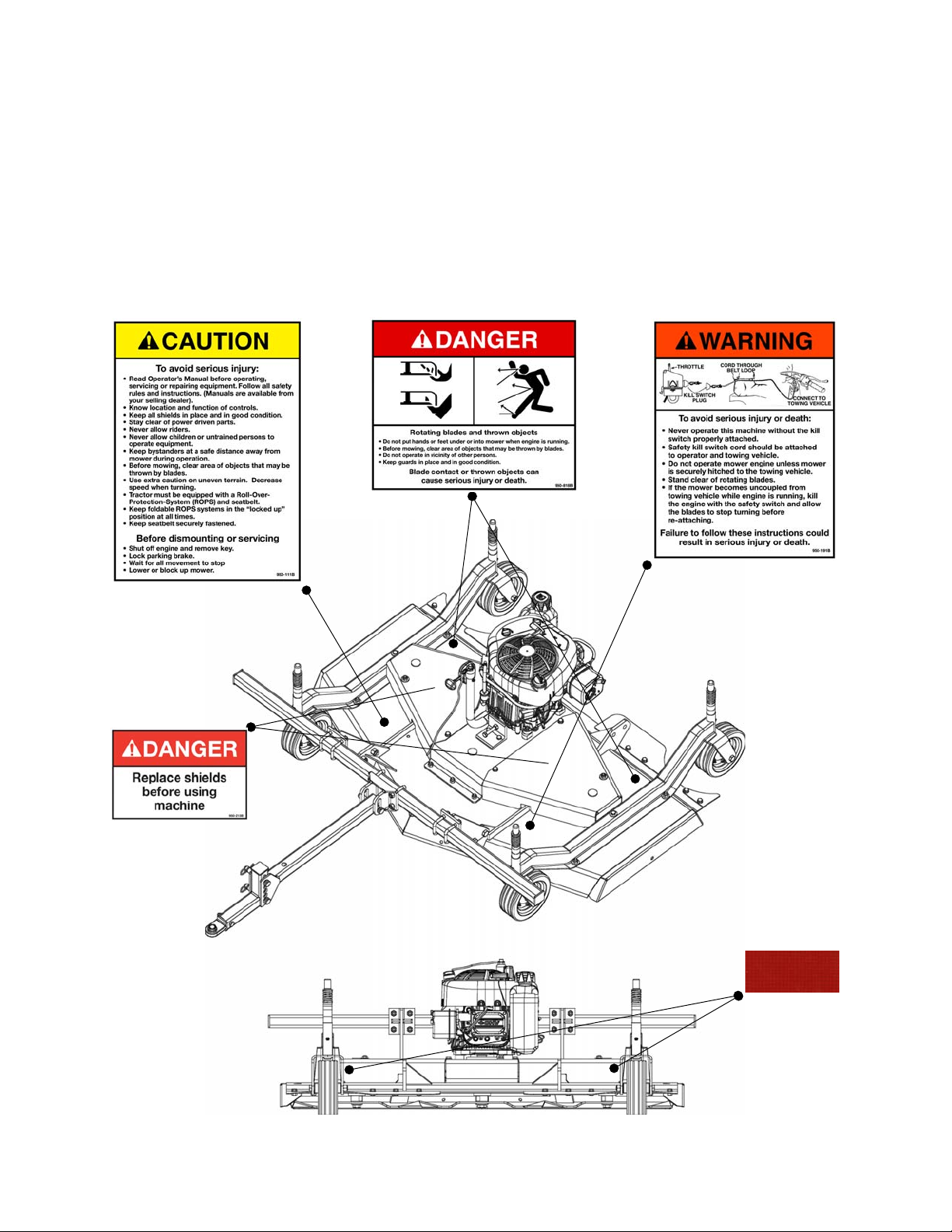
5. Test the safety kill switch on the mower to ensure that the mower will cut off when
key is removed.
6. Before operating, attach the kill switch rope to the operator’s belt strap and to the
towing vehicle on the front of operator’s seat.
7. Always stop the towing vehicle, set brake, shut off both the mower engine and the
towing vehicle engine, remove the ignition key and allow mower blades to come to a
complete stop before dismounting towing vehicle. Never leave equipment
unattended with the towing vehicle running.
8. Never place hands or feet under mower with engine running or before you are sure
all motion has stopped. Stay clear of all moving parts.
9. Do not allow riders on the mower or towing vehicle at any time. There is no safe
place for riders.
10.Do not operate unless all personnel, livestock and pets are at least 300 feet away to
prevent injury by thrown objects.
11.Before backing up, turn off mower engine and look behind carefully.
12.Install and secure all guards and shields before starting or operating.
13.Keep hands, feet, hair and clothing away from moving parts.
14.This rotary mower is designed for use with all terrain vehicles (ATVs) or garden
tractors.
15.Never operate towing vehicle and mower under trees with low hanging limbs.
Operators can be knocked off the towing vehicle and then run over by the rotating
blades.
16.The rotating parts of this machine have been designed and tested for rugged use.
However, they could fail upon impact with heavy, solid objects such as steel guard
rails and concrete abutments. Such impact could cause the broken objects to be
thrown outward at very high velocities. To reduce the possibility of property damage,
serious injury, or even death, never allow the cutting blades to contact such
obstacles.
17.Frequently check mower blades. They should be sharp, free of nicks and cracks and
securely fastened.
18.Stop mower immediately upon striking an obstruction. Turn mower engine off, turn
towing vehicle engine off, remove key, disconnect spark plug wire, set towing vehicle
brake and wait for all movement to stop. Inspect and repair any damage before
resuming operation.
19.Stay alert for holes, rocks and roots in the terrain and other hidden hazards. Keep
away from drop-offs.
20.Use extreme care and maintain minimum ground speed when transporting on
hillside, over rough ground and when operating close to ditches or fences. Be careful
when turning sharp corners.
21.Reduce speed on slopes and sharp turns to minimize tipping or loss of control. Be
careful when changing directions on slopes. Do not start or stop suddenly on slopes.
Avoid operation on steep slopes.
22.When making tight turns, do not allow pull hitch to ride up on towing vehicle tires.
OPERATION 10 BEFCO
CYCLONE OPERATOR’SMANUAL

23.Inspect the entire machine periodically2. Look for loose fasteners, worn or broken
parts, and leaky or loose fittings.
24.Pass diagonally through sharp dips and avoid sharp drops to prevent “hanging up”
towing vehicle and mower.
25.Avoid sudden starts and stops while traveling up or downhill.
26.Always cut down slopes; never across the face. Avoid operation on steep slopes.
Slow down on sharp turns and slopes to prevent tipping and/or loss of control.
3.02 - Set Up
Notice to dealer: Pre-delivery setup and service including lubrication is the
responsibility of the authorized dealer. It is up to him to assure that the machine is in
perfect condition and ready to be used. It is his responsibility to ensure that the
customer is aware of all safety aspects and operational procedures for the mower and
the engine. He must also fill out the Pre-Delivery Checklist3prior to delivering the
mower.
CAUTION: Stand clear of bands when cutting as they could be under sufficient
tension to cause them to fly loose. Take care in removing bands and wire, they
often have extremely sharp edges and cut very easily.
3.03 - Assembly Instructions
C30-CE5H mowers are shipped almost completely assembled. Follow the instructions
below to assemble remaining items on the mower (see fig. 3).
OPERATION 11 BEFCO
CYCLONE OPERATOR’SMANUAL
3See Chapter 7 - Pre-Delivery Checklist.
2See Chapter 4 - Maintenance.
Fig. 3 - Assembly.
drawbar
hitch bracket
ball joint
pins
hairpin cotter
drawbar attachment bracket

CAUTION: Engine is shipped without oil. Fill oil reservoir to the correct level
before starting the engine. See the engine manufacturer’s operator’s manual for
further information on engine.
To assemble the C30-CE5H mower proceed as follows:
1. Using a crow bar open the top of the crate then remove the sides of the crate.
2. Add oil to the engine. Use the dip stick to fill to the correct level.
3. Position the drawbar inside the drawbar attachment bracket and secure it in place
using the Ø19 pin and Ø4 cotter pin.
4. Secure the hitch bracket to the drawbar using two Ø19 pins and two Ø4 cotter pins.
Use the holes that will allow you to keep the drawbar as level as possible when
attached to the tractor. Ball joint will arrive already assembled to hitch bracket.
Note: All hardware needed for assembly will be found on the machine. Assembly will be
easier if all parts are loosely assembled before tightening the hardware.
3.04 - Cutting Height Adjustment
WARNING: Keep hands and feet away from moving blades.
Be sure both towing vehicle engine and mower engine are off, spark plug wire is
disconnected, parking brake is locked, and key is removed before making any
adjustments.
Before working under mower install blocks under the deck to prevent it from
falling.
OPERATION 12 BEFCO
CYCLONE OPERATOR’SMANUAL
Fig. 4
The cutting height is
adjusted by moving the
height adjustment spacers
on the wheel yokes above or
below the wheel arm.

The cutting height is the distance from the blades to the ground. The cutting height is
adjusted by moving the spacers on the wheel yokes.Placing spacers between the
wheel arm and the wheel yoke raises the cutting height by the size of the spacer.
Removing the spacers lowers it by the same height (see fig. 4).
The cutting height is adjustable from 1” to 4”. All mowers are supplied spacers of
1/4", 1/2", and 1" heights to allow operator to obtain the desired cutting height. When
there are no spacers between the bottom of the wheel arm and the top of the wheel
yoke the mower will cut at approximately 1". Be sure all wheel arms are adjusted
equally. This is the only way to ensure a completely uniform cut. Cutting lower than 2”
under most circumstances should be avoided.
IMPORTANT: Very low cutting heights should be avoided. Damaging shock loads
occur when the blades strike the ground repeatedly. This can cause damage to
the mower.
To adjust cutting height do the following:
1. Place mower on a level surface.
2. Turn off engine and set parking break of vehicle.
3. Turn off engine on mower.
4. Disconnect the drawbar from the mower and disconnect the hitch bracket from the
drawbar.
5. Secure the drawbar to the supplied height adjustment stand using a Ø19 pin and Ø4
cotter pin (see fig. 5) .
6. Place the height adjustment stand to the side of the mower and position the "U"
shaped tip of the stand to straddle the side of the deck (see fig. 6).
7. Using the weight of your body, push the drawbar down towards the ground. This will
cause the side of the deck to be raised off the ground.
8. Once raised off the ground, secure the mower with blocks underneath it to prevent it
from falling. Do not rely on mower lifting tool alone to keep the mower raised off the
ground.
9. Remove the plastic cap and the M12 nuts from the wheel yokes that are raised from
the ground.
10.Remove the spring and washer on top of the yoke, add spacers below the wheel
arm to increase cutting height, or on top of the wheel arm to reduce the cutting
height.
11.Reassemble yokes to wheel arm, replace spring and washer and secure them with
M12 nut. Replace plastic caps.
12.Remove blocks and slowly raise drawbar off the ground to lower down the mower
deck.
13.Repeat steps 6 through 12 on other side of the mower deck.
14.Verify that all wheels are set at the same height.
15.Disconnect drawbar from the height adjustment stand.
16.Reassemble hitch bracket to the drawbar using two Ø19 pins and two Ø4 cotter
pins.
17.Secure the drawbar to the mower using the remaining Ø19 pin and Ø4 cotter pin.
OPERATION 13 BEFCO
CYCLONE OPERATOR’SMANUAL

Each C30-CE5H is supplied standard with the necessary tools to raise the deck (see
fig. 5). The height adjustment stand connected to the drawbar will allow you to raise
one side of the deck at a time to adjust the wheels to the desired cutting height (see fig.
6).
3.05 - Pre-Operational Check
IMPORTANT: Check each of the following, carefully, prior to engaging the equipment:
1. The spindle bearings have been greased.
2. The belts for proper tension.
3. No wrappings or foreign objects are around the blades or belts.
4. The blades are properly installed and the blade bolts properly torqued4.
5. All hardware is tight.
6. All safety shields and guards are in place and tightly attached.
7. No people or animals are in the work area.
WARNING: Shut off mower engine and remove spark plug wire from spark plug
before making adjustments, servicing or cleaning the machine. Failure to do so
could result in accidental starting of engine causing possible injury or death.
3.06 - Attaching to the Vehicle
The hitch on the C30-CE5H allows the mower to be set up to be either towed behind the
vehicle or pushed in front of the vehicle.
OPERATION 14 BEFCO
CYCLONE OPERATOR’SMANUAL
4See Table 1, page 29.
Fig. 5 - Mower lifiting tool.
drawbar
height adjustment
stand
Fig. 6 - Raising the mower to adjust cutting height.

To attach the mower to be towed behind the tractor do the following:
1. Back the towing vehicle up to the mower.
2. Turn off engine and set parking break of vehicle.
3. Attach a category 1 hitch pin to towing vehicle drawbar.
4. Slide a rubber washer and mower swivel hitch on the hitch pin and secure with a
lynch pin. Make sure hitch pin goes completely through each piece and is secured to
prevent accidental separation.
5. Tighten the spring loaded nuts on the front wheels of the mower to help the unit
track behind the tractor correctly. Set for the back wheels to have some pivot to help
the mower turn with the tractor (see fig. 9).
To attach the mower to be pushed in front of the ATV/UTV do the following:
1. Secure the 2” receiver bracket to the front hitch of the ATV/UTV using the supplied
bolt. Tightening the bolt will remove any slack between the male and female part of
the receiver. This will allow for the mower to track better and remove any slack that
can be noticed when turning.
2. Turn off engine and set parking break of vehicle.
OPERATION 15 BEFCO
CYCLONE OPERATOR’SMANUAL
Fig. 7 - Unit when rear mounted.
tractor
ATV / UTV
Fig. 8 - Unit when front mounted.
tractor
ATV / UTV

3. With the hitch installed, drive the ATV/UTV behind the mower and secure the hitch
using the Ø19 pin and Ø4 cotter pin.
4. Loosen the spring loaded nuts to set all four wheels on the mower to have a little
room to pivot, this will allow the mower to turn in the direction that the ATV/UTV is
turning (see fig. 9). If you loosen the nuts excessively, the mower will have a
tendency to swing side to side. If on the other hand you tighten the spring loaded
nuts excessively, the wheels will not turn properly in the direction that the ATV/UTV
is turning.
CAUTION: Towing vehicle front end stability is necessary for safe operation when
pulling equipment.
CAUTION: Always ensure that the towing vehicle’s tire pressure is correct
according to the vehicle’s operator’s manual.
DANGER: Failure to ensure a secure hitching of the implement to the towing
vehicle can cause serious injury or death.
3.07 - Offsetting the Mower
The hitch on the C30-CE5H allows for the mower to be set up to be offset up to 75” to
the left or right side of the tractor. In certain cases, operators like to offset the mower
because it allows them to increase the mowing width of their belly mounted mower. In
other cases, offsetting the mower allows the operator to safely mow closer to obstacles
(for example, near the edge of a pond or under trees).
OPERATION 16 BEFCO
CYCLONE OPERATOR’SMANUAL
Fig. 9 - Adjusting wheel tension.
Turn counter-clockwise to loosen spring loaded
nuts to allow more wheel pivot
Turn clockwise to tighten spring loaded nuts
to reduce wheel pivot

To offset the mower do the following:
1. Loosen the nuts that secure the “U” bolts to the offset bar.
2. Position the mower and the offset bar in the desired position to the left or right of the
tractor.
3. Secure the nuts back on the “U” bolts.
3.08 - Start Up
Before starting to mow, never forget that the operator is responsible for the following:
1. Safe and correct driving of the towing vehicle and mower.
2. To learn precise safe operating procedures for both the towing vehicle and the
mower.
3. To ensure all maintenance and lubrication has been performed on the mower.
4. To have read and understood all safety aspects for the mower and the engine in the
respective operator’s manuals.
5. To have read and understood all safety decals on the mower.
6. Checking the condition of the blades. Worn or damaged blades should be changed
before starting5.
7. Checking to ensure that the cutting edge is the leading edge of the blade6.
8. Checking that there is no wire, weed, grass or other material wrapped around
blades.
9. Checking the towing vehicle tires for the proper pressure in accordance with the
tractor operator’s manual.
10.Making sure the proper attire is worn. Avoiding loose fitting clothing which can
become entangled. Wearing sturdy, tough-soled work shoes and protective
equipment for eyes, hands, ears and head. Never operate mower in bare feet,
sandals or sneakers.
OPERATION 17 BEFCO
CYCLONE OPERATOR’SMANUAL
6See Section 4.03 - Blade Maintenance.
5See Section 4.03 - Blade Maintenance.
Fig. 10 - Offsetting the mower.
up to 75"up to 75"

11.Checking area for stones, branches and other debris that might be thrown.
12.Ensuring proper lighting is available, sunlight or good artificial lighting.
13.Ensuring the kill switch safety is properly attached.
To start mower engine do the following:
1. Install the kill switch plug.
2. Open the fuel valve.
3. Push throttle in the “CHOKE” position. If the engine is warm, place the throttle in
“SLOW” position.
4. Place one foot on the mower deck and one foot firmly anchored on ground. Make
sure foot on ground does not get underneath mower. Pull starter cord briskly
returning slowly until engine starts.
5. When engine cranks, slow to idle and allow the engine to warm up for several
minutes. When engine is warm adjust throttle to desired speed.
NOTE: If engine is hard to crank consult the engine manufacturer’s operator’s manual.
DANGER: Keep hands and feet away from underneath the mower. When starting
the engine place one foot on the mower deck and one foot firmly anchored to the
ground safely away from underneath the mower deck.
To start cutting ensure that:
1. The kill switch tether cord is connected from the switch through the operator’s belt
loop to towing vehicle forward of operator’s seat.
2. Parking brake is released.
3. The lowest gear is selected in order to begin cutting at a slow speed. Adjust speed
gradually in relation to the condition of the ground.
DANGER: Ensure that the safety kill switch is working properly. Test to make
sure that the mower will cut off when the switch is removed. Never operate the
mower without the safety kill switch properly attached. Failure to do so could
cause serious injury or death.
To shut down mower engine do the following:
1. Idle the engine down.
2. Set parking brake.
3. Pull out kill switch plug.
4. Stop the engine of the towing vehicle.
5. Close fuel valve.
6. Allow the mower blades to come to a complete stop before dismounting.
OPERATION 18 BEFCO
CYCLONE OPERATOR’SMANUAL

3.09 - Working Speed
The mowing speed depends on ground conditions, mowing height, and grass thickness.
Only a test run will enable you to gauge the optimal working speed for your conditions.
Under most conditions a 3 to 5 mph ground speed is best. As a rule of thumb, and if the
conditions permit, grass dispersion is increased by higher ground speeds.
The mulching kit is an option available for our mowers. This kit, containing 3 multilevel
cutting edge blades and add-on containment baffling which bolts to the underside of the
mower deck, mulches and pulverizes grass and leaves.
Another benefit of the mulching kit is safety. In fact, the kit greatly reduces the possibility
of thrown objects. This is particularly important when mowing around schools, public
parks and golf courses.
If you are using a mulching kit, you need to reduce your ground speed to under 2 mph
(see fig. 11).
3.10 - Operating Techniques
All of the following factors are important in selecting the proper forward speed:
1. Height of grass.
2. Type of grass.
3. Density of grass.
4. Type of terrain.
5. Grass condition, wet or dry.
This mower has been designed to cut grass with heights from 4” to 8”. It is
recommended to avoid cutting grass taller than 10”. For the best results, try cutting the
OPERATION 19 BEFCO
CYCLONE OPERATOR’SMANUAL
Fig. 11
The mulching kit is an
available option,
consisting in 3
multilevel cutting edge
blades and add-on
containment baffling
which bolts to the
underside of the mower
deck, to mulch and
pulverize grass and
leaves.

grass at least once per week during growing season. Tall, dense grass should be cut at
low speed, while thin medium grass can be cut at a faster ground speed. For cleaner
cuts and efficient mowing, the blades must be kept sharp7.
Under certain conditions, towing vehicle tires may roll some grass down and prevent it
from being cut at the same height as the surrounding area. If this occurs reduce the
towing vehicle ground speed. The lower ground speed will permit the grass to at least
partially rebound. Under some conditions grass will not rebound enough to be cut
evenly, resulting in an uneven appearance. In general, lower cutting height gives a more
even cut with less tendency to leave tire tracks. If cut is still not satisfactory, cut the area
twice.
Mow extremely tall grass twice. On the first pass use a high cutting height. On the
second pass position the mower at the desired height and, when practical, mow at a
right angle in travel to the first pass.
It is better to cut grass more often, than too short. Short grass deteriorates rapidly in hot
weather and invites weed growth during growing season.
Plan your pattern to travel straight forward whenever possible. The rear tires of the
mower are locked in the running position to help stabilize the mower on inclines.
DANGER: The mower blades can throw objects hundreds of feet which could
result in personal or property damage.
Pick up all rocks and other debris before mowing.
Enter new areas carefully. Cut grass higher at first, allowing mower to clear
hidden objects.
CAUTION: For emergency reasons learn how to stop the towing vehicle and
mower quickly. Stop mower engine, stop towing vehicle engine, lock parking
brake and allow the mower blades to come to a complete stop before
dismounting the tractor.
3.11 - Uneven Terrain
DANGER: Be careful of rollover when operating towing vehicle and mower over
uneven ground.
The following precautions should always be observed when working on uneven terrain:
1. In extremely uneven terrain rear wheel weights, front tractor weights, and/or tire
ballast should be used to improve stability.
2. Observe the type of terrain and develop a safe working pattern.
OPERATION 20 BEFCO
CYCLONE OPERATOR’SMANUAL
7See Sharpening Blades in section 4.03 - Blade Maintenance.
This manual suits for next models
1
Table of contents
Other BEFCO Lawn Mower manuals
Popular Lawn Mower manuals by other brands

MTD
MTD 115-240A Owner's operating service instruction manual

Gardena
Gardena PowerMax 32/36V P4A Operator's manual

Craftsman
Craftsman 917.273400 owner's manual

Husqvarna
Husqvarna AUTOMOWER 520 quick guide

Fieldmann
Fieldmann FZR 70375-0 manual

Grizzly Tools
Grizzly Tools ARM 2033-22 Lion Set Translation of the original instructions for use