Behlen WRSJ Troubleshooting guide

DOUBLE ROW
STRIP JOINING PRESS
MODEL “WRSJ”
OPERATING INSTRUCTIONS & SERVICE INFORMATION
TECHNICAL
INFORMATION
61018
F-10929-7 Rev. 9-25-07 7-1-98
NOTE: If pink sheets are included in this manual, refer to them for latest revisions.

IMPORTANT CONCERNS
WHEN MOVING YOUR SPLICE DETECTION
HOLE PUNCH FROM ONE DIE TO ANOTHER
In late 1997 we made a design change to our basic strip joining dies. This change involved making both upper and
lower die shoes thicker by approximately 11/16” (17 ½ mm). This change also eliminated the mounting plates and made
the entire unit more rigid.
This change also created a serious problem when a splice detection hole punch assembly is removed from an old style
die and placed in a new style die. The result will be considerable damage to the entire die assembly.
Do not, under any circumstances, remove a hole punch assembly from an
old style die and place it in a new style die. Any damage resulting from this
is excluded from any and all warrantees.
To best determine whether you can interchange your hole punch assembly from one die to another, measure the thick-
ness of the die shoe in both dies. If there is a thickness difference of more than 0.125” (3mm), please consult Behlen
Mfg. Co. before proceeding.
F-19853 7-18-02

SAFETY
Watch for this symbol. It points out important safety
precautions. It means “Attention - Be Alert! Your
Safety Is Involved.”
Several decals are attached to the press at various loca-
tions to call attention to your personal safety. Read and
heed the message and be alert to possible injury or fatali-
ty.
It is your responsibility as a supervisor or operator to
know what hazards exist and to make these known to all
other personnel working the area so that they too may
take any necessary safety precautions that may be
required.
If the decal(s) become damaged or detached, contact
your Behlen representative or the Behlen Mfg. Co. for
replacements.
Guards and shields are for your protection. Keep
them in place and secure while machine is in opera-
tion.
Replace safety shields that may have been dam-
aged or removed for servicing purposes and fasten
securely before operating machinery.
Enforce the use of safety blocks whenever dies are
being adjusted, repaired or replaced in the press.
Before you perform any service on the press, make
certain that the main power disconnect switch is
locked in the off position.
The design and installation of any and all safety and
guarding equipment for the passage of the metal strip
through the Strip Joining Press that may be necessary to
conform with O.S.H.A. or any applicable safety regula-
tions to meet your particular line configuration are your
responsibility, not that of Behlen Mfg. Co. Make the elec-
trical connections according to the enclosed schematic.
In the event the press fails to operate the die (even
though the pumps are running), it is possible the pump
motor is running in reverse. Check the rotation. This sit-
uation can be corrected by interchanging any 2 of the 3
phase line leads.
Before each stitching operation, check the press to make
sure the die is free of all foreign material.
BEHLEN STRIP JOINING PRESS
SERVICE AND OPERATING INSTRUCTIONS
1. Oil level should be kept to near the top of the sight
gauge. This machine was filled to the proper level at
the factory with MOBIL DTE-26 hydraulic fluid unless
otherwise specified.
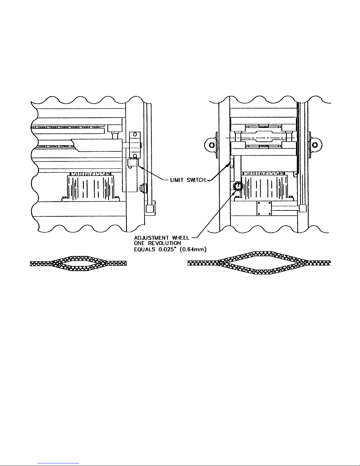
2. Adjust stitch height switch for various thicknesses of
material if necessary.
3. Lubricate the guide posts on the die as required.
Keep the die area free of all foreign material.
4. Adjust the limit switch on the ram to coast to a stop at
bottom of the cylinder stroke.
5.
To perform the stitching operation, stop the trailing end
of leading material, holding about 14” (35.5cm) in the
machine. Next, insert 14” (35.5cm) of the leading end
of the next coil, either above or below the trailing end.
Push the “UP” control switch on the machine. In one
cycle, the stitch is completed. During the cycle, the die
will move up, make the stitch, reverse and stop in the
original position. Check to be sure the limit switch
shuts the press off at the finish of each stitch.
6. The Strip Joining Press can be cycled two or more
times to form additional rows of stitches that may be
required to obtain a holding stitch on lighter gauge
material. This is accomplished by cycling the
machine once, advancing the joined sheets forward
out of the die area, and then cycling the machine
again. For each additional two rows of stitches to be
formed, overlap the coils approximately 14” (35.5cm)
longer than required for two rows of stitches. Each
cycle of the machine forms two rows of stitches. A
pre-cut strip (needle) can be inserted through one row
of stitches if necessary, after two or more rows of
stitches are formed, in order to obtain a holding stich
on lighter gauge material.
7. The relief valves are pre-set at the factory and should
not be field adjusted.
8.
THE STRIPPER PLATES AND/OR COMPLETE DIE
SHOULD BE REMOVED PERIODICALLY AND THOR-
OUGHLY CLEANED OF ALL CHIPS AND FOREIGN
MATERIAL. THIS SHOULD BE DONE POSSIBLY ONCE
A MONTH UNDER SEVERE CONDITIONS.
INSTRUCTIONS FOR ORDERING
REPLACEMENT PARTS
In order to insure that the correct parts will be provided,
all orders for replacement parts must include the serial
number and model of the strip joiner. These numbers
may be found on the name plates located on the die and
on the press frame near the controls.
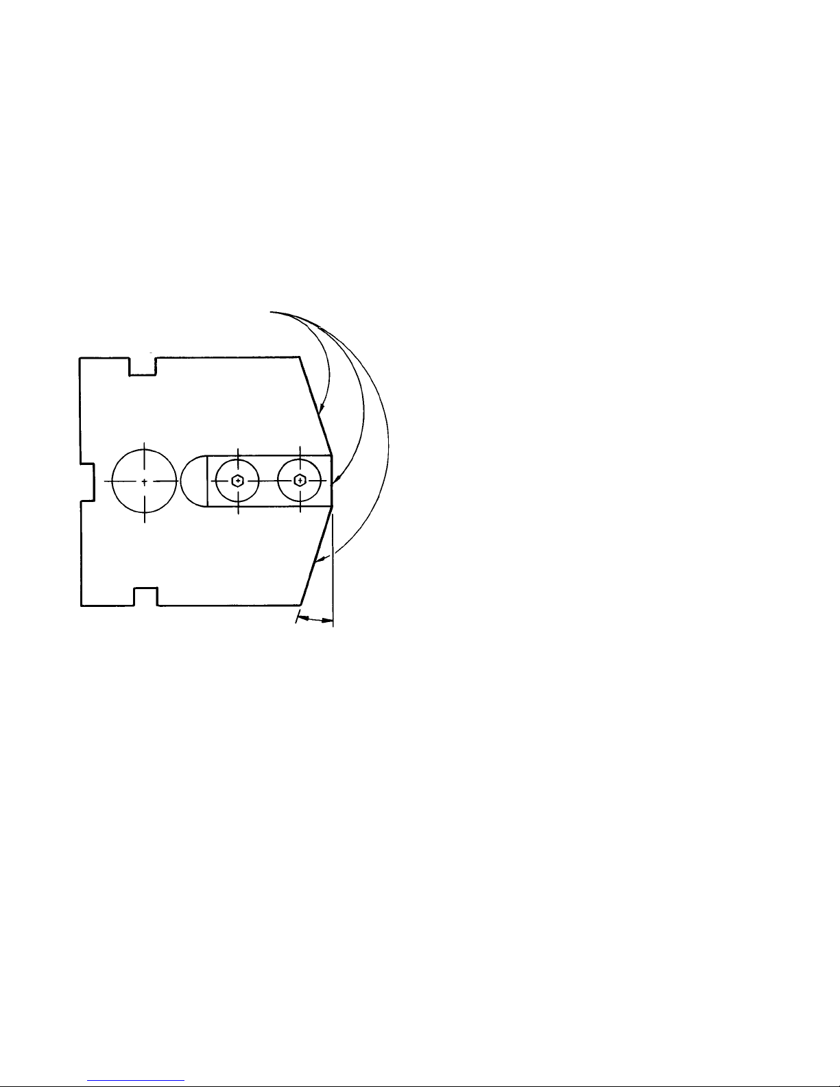
INSTRUCTIONS FOR SERVICING THE DIE
Reference to die teeth in the following procedure means
punch with insert assembled.
For 18° angle on punch - part no. 615 061, assembly
includes punch 616 116 with insert 616 117.
For 9° angle on punch - part no. 615 067, assembly
includes punch 616 131 with insert 616 117.
DIE REMOVAL INSTRUCTIONS
1. Lock out machine.
2. Place wooden block (2 places) into die opening.
NOTE: Blocks need to be 3-3/8” (86mm) to 3-1/2”
(89mm) in height.
3. Loosen bottom bolts and remove from die.
4. Using a bottle jack each end of die, jack bottom die
until wooden blocks contact upper die.
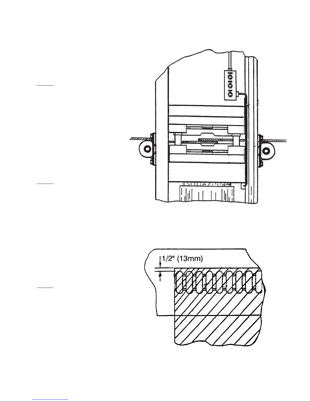
5.
Place 1/2” (13mm) dia. round rods under raised die.
6. Loosen and remove top bolts from die.
7. Lower die set onto rods and remove bottle jacks.
!!
!!
!!
!!
!!
PRE-OPERATIONAL PROCEDURE
F-19282-2 Rev. 7-5-05 7-1-98
1
!!

8. Push die out onto die cart.
9. Reverse procedure to install die.
INSTRUCTIONS FOR SHARPENING TEETH
Remove the entire die from the press as a unit and sepa-
rate it into a top and bottom die set. Keep all teeth
attached to the die plates, however, the die shoes may be
removed from the die plates for ease in grinding teeth.
The stripper plates and urethane stripper plugs must be
removed before the teeth are ground. Grind teeth of the
top and bottom as a unit. Teeth shall be ground on tops
and both adjoining angled sides. The sides are ground
at an angle of 9° or 18°, depending on machine model.
This angle is not critical, however, both sides should be
the same. The die may now be reassembled and placed
back into the machine. The die and press each have a
marking labeled “Front”. The die is symmetrical, but it
should be placed back in the press as originally assem-
bled. If grinding equipment is not available to sharpen
teeth as a unit, they may be ground individually. Read
the instructions for the procedure to remove and replace
teeth.
PROCEDURE FOR REPLACING TEETH
OR OTHER PARTS OF THE DIE
Remove the die from the press as a unit and separate it
into the top and bottom die sets. Next, remove the strip-
per plates and and urethane stripper plugs, tooth clamps
and rod. Teeth that need replacing may now be lifted off
the die plate. In replacing new teeth, it is very important
that all parts be cleaned thoroughly, making certain that
no lint from wiping rags or other foreign material gets
between the teeth. A spare tooth should be used for indi-
vidually checking clearance between all teeth. This clear-
ance should be .002” (0.05mm) minimum to .007”
(0.18mm) maximum around all parts of mating teeth.
After the clearance is determined to be correct, the teeth
in the bottom die set should be securely fastened by
means of the clamps and rod. The nuts on the rod
should be tightened with a torque wrench to 120 foot
pounds (163 N-M).
The two sets of set screws in each end keeper should
also be tightened at this time. These are locked in
placed with a second set of socket head set screws. The
teeth in the top die set should be tightened securely with
the rod, but only tight enough with the clamps to hold
them in place so they are allowed to move for adjustment
after the top and bottom die sections have been slipped
together. The top and bottom die sections should be
slipped together without the urethane stripper plugs and
stripper plates. At this time, clearance between top and
bottom mating teeth should be checked and adjusted if
necessary. This adjustment can be accomplished by
means of the set screws in the keepers on both ends of
the top die section. After it is determined that the die
meshes properly, the clamps of the top die should be
tightened and the urethane stripper plugs and stripper
plates replaced in the die. The entire die may now be
returned to the press.
PROCEDURE FOR REPLACING CYLINDER SEAL
1. Remove the urethane roller (615059) from one side of
the press.
2. Remove the top and bottom bolts holding the com-
plete die in place, and remove the complete die unit
from the press.
3. Remove the screws that secure the ram plate to the
pistons and then remove both ram plate skirts
(616113) and the ram plate (616112).
4.
Bolt a long bar or pipe to the piston (616002) - there is
one threaded hole in the top of each piston. Remove the
piston upward from the cylinder (616099).
5. Replace the defective seal (3308009) in the cylinder,
with the lips of the seal pointing downwards.
Lubricate the seal for easier assembly.
6. Also, check the “O”ring #331 (2748014), under the
cylinder, for leakage and replace as required.
7. Reverse steps 1, 2, 3 and 4 to assemble. When
replacing pistons, apply pressure downwards as
evenly as possible so that lips of the seals will not be
cut or damaged.
HOLE PUNCH FOR SPLICE DETECTION
For strip joining dies equipped with a hole punch assem-
bly, 1½” or 2” (38mm or 51mm) diameter on the exit side
of the die, you can sharpen the round punch portion and
the die plate one or more times until a total of 0.075” to
0.100” (1.9mm to 2.5mm) maximum has been removed,
depending upon the thickness of the material being
joined. The following spare parts can be ordered by
complete description and you must indicate the diameter
of the hole punch, press model number and serial num-
ber.
1. Spare hole punch and die plate. (You will need to
locate and drill dowel pin holes to properly match up
the new mating punch and die plate.)
2. Urethane stripper ring (616270) over the hole punch
for splice detection assembly.
Original Length 2.500” (63.5mm)
Sharpen these three surfaces.
Do not grind off more than .060” (1.5mm)
total during successive sharpenings.
F-13569-5 Rev. 7-5-05 5-15-80
2
9° or 18° depending on machine model.

OPERATION FOR BEHLEN STRIP JOINER PRESS
STEP 1
FEED INCOMING EDGE OF COIL
INTO DIE AREA AS SHOWN IN
ILL. 1.1 OVERLAP MAY VARY
DUE TO THE NEED FOR MORE
ROWS OF STITCHES. STRIP
EDGES SHOULD BE NO CLOSER
THAN 1/2” (13MM) TO
STRIPPER PLATE POCKETS AS
SHOWN IN ILL. 1.2.
STEP 2
AFTER ALL CLEAR HAS BEEN
ANNOUNCED FOR SAFETY
PURPOSES, PRESS THE CLOSE
BUTTON(S) FOR CYCLE
ACTIVATION. THE MACHINE
WILL RUN THROUGH COMPLETE
CYCLE AND TURN OFF
AUTOMATICALLY.
STEP 3
JOG THE JOINED MATERIAL COIL
FOR LOCKING THE STITCHES.
F-18221-1 37-1-98
ILLUS. 1.2
ILLUS. 1.1

F-19587 44-15-00
FAIL TENSION DIAGRAM FOR TYPICAL STEEL & ALUMINUM
Thickness of Each Coil End - In Inches (mm)
MILD STEEL 45,000 PSI (32 Kg/mm2)YIELD
ALUMINUM 5052 H-32 23,000 PSI (16 Kg/mm2) YIELD
Single Row Die - Read as pounds (Kg) per 1½” (38mm) of coil width.
Double Row Die - Multiply by 2 and read as pounds (Kg) per 1½” (38mm) of coil width.
Single Row Die with “W15T” as part of model number - Read as pounds (Kg) per 3” (76.2mm) of coil width.
Shift force is 25% of fail for steel and 60% for aluminum.

F-19180MA 57-1-98
Rev. 3-1-99
STITCH HEIGHT ADJUSTMENT
Adjust the depth switch as required to produce a good joint. The switch has been preset at the factory for
the maximum material thickness you will run and, in most cases, will work for you. If adjustment of stitch
height has been deemed necessary, each full turn will move the stitch height 0.025” (0.64mm). Adjust until
satisfactory results are met. For a deeper stitch, turn adjustment wheel counter-clockwise. For a shallower-
stitch, turn adjustment wheel clockwise.
In this case, the stitch is incomplete.
Turn the adjustment wheel counter-
clockwise to make a deeper stitch.
In this case, the stitch is too deep causing
the material to fracture. Turn the adjustment
wheel clockwise to make a shallower stitch.

NUMBERED PARTS
Ref. Part No. Description
1 1328-092 Bolt, Rd. Hd. Stove ¼” x ½”
2 1588-028 Connector, ¾” St. Liquid Tight
3 1588-029 Connector, ¾” x 90° Liquid Tight
5 1588-065 Connector, 1½” x 90° Liquid Tight
6 1508-003 Clamp, ½” Conduit
7 1508-013 Clamp, 1” Conduit
8 1749-150 Conduit, ¾” Liquid Tight
9 1749-110 Conduit, ½” Liquid Tight
10 1749-160 Conduit, 1½ Liquid Tight
11 2688-022 Nut, Hex 5/8” NC
12 3188-039 Screw, Hex Hd. Cap ½” NC x 3”
13 2688-010 Nut, Hex 5/16” NC
14 3188-004 Screw, Hex Hd. Cap ½” NC x 1”
15 3248-037 Screw, Socket Hd. Cap 7/16”
16 3188-042 Screw, Hex Hd. Cap 5/16” NC x ¾”
17 3188-066 Screw, Hex Hd. Cap ¼” NC x ¾”
18 3188-036 Screw, Hex Hd. Cap ½” NC x ½”
19 3188-037 Screw, Hex Hd. Cap 7/16” NC x 3”
20 1328-099 Bolt, Rd. Hd. Stove 3/16” NC x 1”
21 3208-055 Screw, Slot Rd. Hd. 3/16” NC x 2”
22 3248-002 Screw, Socket Hd. Cap 5/8” NC x 2”
23 3188-037 Screw, Socket Hd. Cap 7/16” NC x 3”
24 3248-012 Screw, Socket Hd. Cap 5/8” NC x 3”
25 1588-015 Connector, 1/2” x 90° Liquid Tight
27 3248-026 Screw, Socket Hd. Cap 1” NC x 2”
28 3248-009 Screw, Scoket Hd. Cap 1/2” NC x 1/2’
29 3948-001 Washer, Wrought 5/16”
30 3948-002 Washer, Wrought ½”
31 3948-016 Washer, Wrought 1/4”
32 1788-030 Elbow, 1/2” x 90° Pulling
33 3948-028 Washer, Lock ½”
34 3948-019 Washer, Lock 5/8”
F-8550-5 6Rev. 9-25-07 7-1-98

DOUBLE ROW
WRSJ STITCHING DIE
PARTS IDENTIFICATION
U.S. Patent No. 3,728,779
Foreign patents and Foreign patents pending.
F-10931-4 77-1-98
Rev. 7-5-05

HYDRAULIC SCHEMATIC
(1) RESERVOIR
(2) PUMPS
(4) RELIEF VALVE
(6) CYLINDER 2, 4, 6, or 8 of Each
(7) PISTON Used Depending On
(8) SEAL Machine Model
(9) MOTOR
F-13571-1 87-1-98

ELECTRICAL CIRCUIT
1 LS LIMIT SWITCH (DOWN)
2 LS LIMIT SWITCH (DEPTH SWITCH)
1 M, 2 M MOTOR STARTER (REVERSING)
M1 INTERLOCK ON 1 M (NO-UP)
M2 INTERLOCK ON 1 M (NC-UP)
M3 INTERLOCK ON 2 M (NC-DOWN)
M4 INTERLOCK ON 2 M (NO-DOWN)
1 MTR PRESS MOTOR
1 PB PUSHBUTTON STOP (NC)
2 PB-1 PUSHBUTTON UP (NO)
2 PB-2 PUSHBUTTON UP (NC)
3 PB-1 PUSHBUTTON DOWN (NO)
3 PB-2 PUSHBUTTON DOWN (NC)
1T TRANSFORMER CONTROL
1 TAS OVERLOAD SWITCH WOUND IN 1 MTR
NOTE: 1 LS HAS ADDITIONAL CONTACTS (2 NO &
1 NC) THAT MAY BE USED FOR INTERLOCKING.
F-7891-3 9Rev. 3-1-99 7-1-98

F-19181 10 7-1-98
SERVICE CONDITIONS
Table 1
Standard Eight hours per day, normal or light
Conditions loading, clean @ 40°C (100°F) max-
imum ambient.
Severe Twenty-four hour per day operation
Conditions or shock loading, vibration, or in dirt
or dust @ 40-50°C (100-120°F)
Extreme Heavy shock or vibration, or dust.
Conditions
LUBRICATION VOLUME
Table 3
NEMA (IEC) Volume in Cubic
Frame Size Inches (cm3)
182 Thru 215 (112 - 132) 0.5 (8)
254 Thru 286 (160 - 180) 1.0 (16)
324 Thru 365 (200 -225) 1.5 (24)
404 Thru 449 (250 - 280) 2.5 (40)
LUBRICATION FREQUENCY
Table 2
BALL BEARINGS
NEMA Standard Severe Extreme
Speed (IEC) Condi- Condi- Condi
Frame tions tions tions
182 (112) 6
Thru 3 Years 1 Year Months
215 (132)
1800 254 (160)
RPM & Thru 2 Years 6 to 12 3
Slower 365 (200) Months Months
404 (225)
Thru 1 Year 6 1 to 3
449 (280) Months Months
3600 3
RPM ALL 6 Months Months 1 Month
ROLLER BEARINGS
For Roller Bearings divide the time periods above by 2.
REPLACEMENT BEARINGS
Your maintenance program will not be complete without
including spare bearings. It must be remembered that
the bearing is a wearable component and therefore
must eventually be replaced. To insure that you are
able to maintain original operation, we recommend the
purchase of spares directly from Reliance Electric.
All bearings used in Reliance motors are subject to
exact specifications and tests necessary to satisfy per-
formance requirements. In this manner, it is possible to
duplicate your present bearing. Markings on the bear-
ings do not indicate complete specifications.

Motors covered by this Instruction Manual are
equipped with several types of bearings. This descrip-
tion covers regreasable anti-friction bearings only.
Non-regreasable ball bearings require no periodic main-
tenance. See I/M B-3654 for oil mist lubricated anti-
friction bearings procedures.
GREASE LUBRICATED BEARINGS
This motor has been properly lubricated at the time of
manufacture and it is not necessary to lubricate at
time of installation unless the motor has been in stor-
age for a period of six months or more.
Lubrication of anti-friction bearings should be done as
a part of a planned maintenance schedule. The
Recommended Lubrication interval should be used as a
guide to establish this schedule.
Cleanliness is important in lubrication. Any grease
used to lubricate anti-friction bearings should be fresh
and free from contamination. Similarly, care should be
taken to properly clean the grease inlet area of the
motor to prevent grease contamination.
RECOMMENDED LUBRICANT
For motors operating in ambient temperatures shown
below, use the following lubricant or its equal.
BALL BEARING MOTORS
OPERATING TEMP. -25°C (-15°F) to 50°C (120°)
CHEVRON OIL SRI NO.2
EXXON UNIREX N2
SHELL OIL CO. DOLIUM BRB
TEXACO, INC. PREMIUM RB
MINIMUM STARTING TEMPERATURE -60°C (-76°F)
SHELL OIL CO. AEROSHELL 7
ROLLER BEARING MOTORS
OPERATING TEMP. -25°C (-15°F) to 50°C (120°F)
CHEVRON OIL BLACK PEARL EP NO.
2
TEXACO, INC. PREMIUM RB
LUBRICATION PROCEDURE
Reliance regreasable anti-friction bearings may be lubri-
cated with the motor running or stationary. Stationary
with the motor warm is preferred.
1. Locate the grease inlet, clean the area and replace
the pipe plug with a grease fitting, if the motor is
not equipped with grease fittings.
2.If motor is equipped with grease drain plug, remove
plug and loosen any hardened grease that may
block drain.
3. Add the recommended volume of the appropriate
lubricant using a hand operated grease gun.
4. Run the motor for two hours.
5. Replace the pipe plug in grease drain.
6. Grease may not relieve from drain. Use only vol-
ume shown in Table 3.
LUBRICATION INSTRUCTIONS
1. Select Service Condition from Table 1.
2. Select Lubrication Frequency from Table 2.
3. Select Lubrication Volume from Table 3.
4. Lubricate the motor at the required frequency with
the required lubricant volume in accordance with
LUBRICATION PROCEDURE.
NOTE: Mixing lubricants is not recommended due to
possible incompatibility. If it is desired to change
lubricant, follow instructions for lubrication and repeat
lubrication a second time after 100 hours of service.
Care must be taken to look for signs of lubricant
incompatibility, such as extreme soupiness visible from
the grease relief drain area, or from the shaft opening.
LUBRICATION OF BEARINGS
F-19182-1 11 Rev. 7-5-05 7-1-98

F-19183 12 7-1-98
CROSS SECTIONAL AND PARTS IDENTIFICATION SECTION AND DRAWINGS.
REF. NO. PARTS DESCRIPTION
1 FRAME
2 STATOR
3 ROTOR/INTERNAL COOLING FAN
4 BACKEND BRACKET
5 FRONTEND BRACKET
6 SHAFT
7 BACKEND BALL BEARINGS
8 BACKEND INNER BERARINS
9 FRONTEND BALL BEARINGS
10 FRONTEND INNER CAP
11 WAVE WASHER, FRONTEND
12 FAN COVER
13 OUTER COOLING FAN
REF. NO. PARTS DESCRIPTION
14 FRONT END BRACKET BOLTS
15 FAN COVER BOLTS
16 EYEBOLT
17 TERMINAL BOX
18 FAN CLAMP
19 GREASE ENTRY
20 CONDENSATION DRAIN
21 KEY
22 SLINGER
23 BACKEND CAP BOLTS
24 GREASE DRAIN
Table of contents