LEMKEN VarioPack 80 WDP 70 User manual

Operating
instructions
Furrow press
VarioPack
- EN -
Safety is our prime concern
Item no. 175_1182
EN-5/11.2020
LEMKEN GmbH & Co. KG
Weseler Straße 5, D-46519 Alpen / Postbox 11 60, D-46515 Alpen
Telephone (0 28 02) 81-0, Telefax (0 28 02) 81-220


1
Dear Customer!
Thank you for the trust you have placed in us by purchasing this machine.
The machine can only be used to its full advantage when operated and used
properly.
When the machine was delivered, you will already have been instructed in opera-
tion, adjustment and maintenance by your dealer. However, this brief instruction
is not a substitute for thorough study of the operating instructions.
Therefore, carefully read the operating instructions before using the machine for
the first time. Please also observe the safety information in the operating instruc-
tions.
Please note that any modifications not expressly mentioned or permitted in these
operating instructions may only be carried out with the written consent of the
manufacturer.
Ordering spare parts
When ordering spare parts, state the type designation and serial number of the
machine. This information can be found on the type plate.
Enter this data in the fields below to ensure it is always to hand.
Type designation:
Serial no.:
Please remember to only use genuine LEMKEN spare parts. Reproduction parts
have a negative influence on the function of the machine, have a shorter service
life and increase maintenance costs in practically all cases.
Please understand that LEMKEN does not assume any warranty for the functional
disadvantages and damages caused by the use of reproduction parts!

2
INTENDED USE
•Before commissioning, please familiarise yourself with your
LEMKEN machine and its operation. These operating instructions
and the safety information will help you with this!
•The LEMKEN VarioPack is built only for standard use for agricultur-
al work (intended use). Any other form of deployment is regarded to
be not in conformance with the designated purpose!
•Intended use also includes adherence to the manufacturer's specified operat-
ing, maintenance and repair conditions!
•The LEMKEN VarioPack may only be used, maintained and repaired by people
who are familiar with it and who are aware of the hazards involved!
•The relevant accident prevention regulations as well as the other generally rec-
ognised safety-related, occupational health and road traffic regulations must be
observed at all times!

3
CONTENTS
INTENDED USE................................................................................................................2
CONTENTS.......................................................................................................................3
1SAFETY AND ACCIDENT PREVENTION REGULATIONS.......................................5
2WARNING STICKERS ................................................................................................8
2.1 General information.................................................................................................. 8
2.2 Meaning of the warning stickers............................................................................. 8
3HOOK LINKAGE.........................................................................................................9
3.1 Catch arm length ...................................................................................................... 9
3.2 Catch hook height .................................................................................................... 9
3.3 Transport position of the catch arms ..................................................................... 9
3.4 Distance of the furrow press to the plough.......................................................... 10
4DRAWBAR FOR SEMI-MOUNTED CONVENTIONAL PLOUGHS .........................10
5VARIOPACK WITH TRACTION DEVICE FOR SEMI-MOUNTED CONVENTIONAL
PLOUGHS.......................................................................................................................11
6HEADSTOCK ............................................................................................................12
7CLEANING TAPES ...................................................................................................12
8SUPPORT FOR SINGLE-ROW FURROW PRESSES .............................................12
9TRAILED MACHINES ...............................................................................................13
9.1 General information................................................................................................ 13
9.2 Pivot linkage with arm, tension lever and tension spring................................... 13
9.2.1 Switching from working to transport position...........................13
9.2.2 Switching from transport to working position...........................14
9.3 Pivot linkage with arm, stop lever and traction rope........................................... 15
9.3.1 Switching from working to transport position...........................15
9.3.2 Switching from transport to working position...........................15
10 ATTACHING AND DETACHING PACKER RINGS...............................................16
11 FRONT MOUNTING HEADSTOCK .......................................................................17
11.1 General information............................................................................................. 17
11.2 Working with front mounting headstock........................................................... 17

4
12 MOUNTING INSTRUCTIONS FOR VARIOPACK..................................................18
12.1 Mounting the hook linkage.................................................................................. 18
12.2 Mounting the headstock...................................................................................... 18
13 MAINTENANCE......................................................................................................18
13.1 Lubrication schedule........................................................................................... 19
13.2 Checking the fluid grease of the bearings.........................................................19
14 INFORMATION FOR DRIVING ON PUBLIC ROADS............................................21
14.1 In the dark or in bad weather ..............................................................................21
14.2 In daylight.............................................................................................................21
14.3 Field of view when used in front mounting .......................................................21
14.4 Transport width....................................................................................................21
15 WEIGHTS................................................................................................................22
16 NOISE, AIRBORNE SOUND..................................................................................22
17 NOTES....................................................................................................................22
EC DECLARATION OF CONFORMITY .........................................................................23

5
1 SAFETY AND ACCIDENT PREVENTION REGULATIONS
General safety information
•Before each commissioning, check the machine and the tractor for
roadworthiness and operational safety!
•In addition to the information in these operating instructions, ob-
serve the generally applicable safety and accident prevention regulations!
•The machine may be used, maintained and repaired only by people who are
familiar with it and are aware of the hazards involved!
•When driving on roads with the machine lifted, the operating lever must be
locked against lowering!
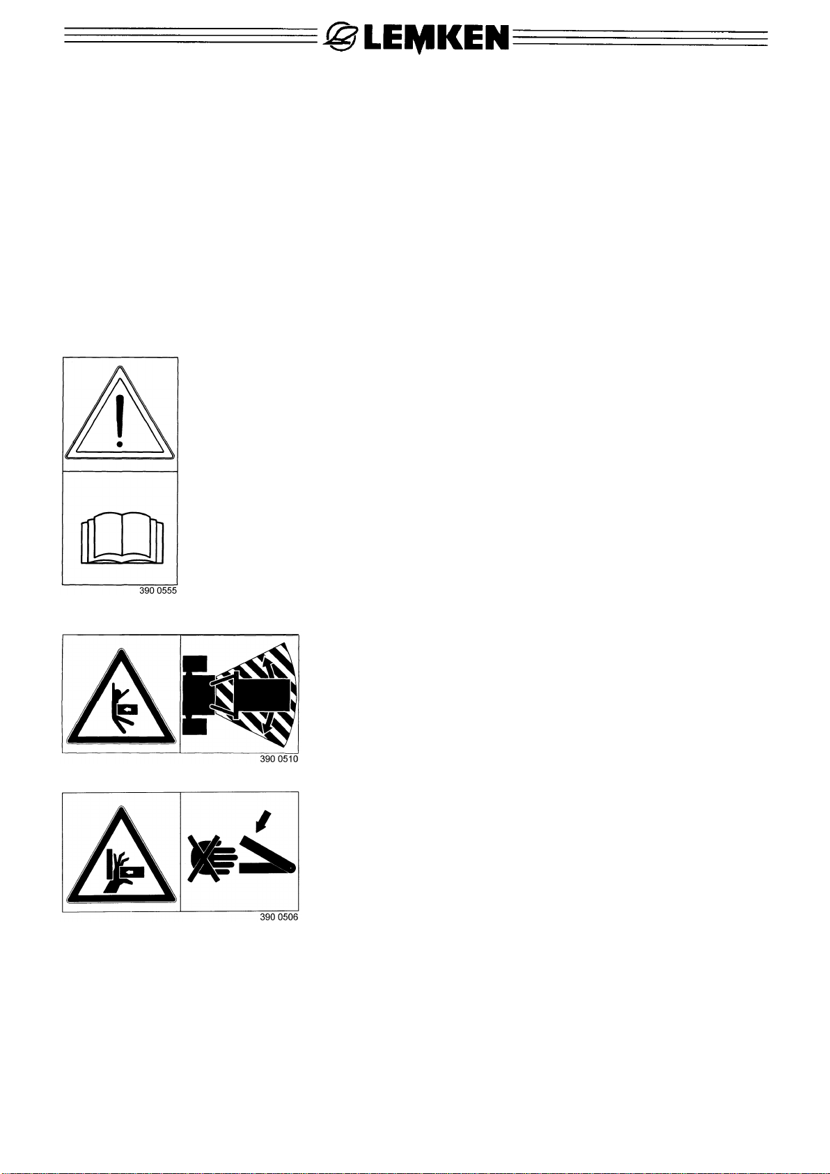
•The attached warning stickers and information signs provide important infor-
mation for safe operation; observance of the information helps to ensure your
safety!
•When driving on public roads, always observe the respective regulations!
•Before starting work, familiarise yourself with all the equipment and operating
elements and their functions. It is too late to do so when working in the field!
•The user's clothing should be tight fitted. Do not wear loose clothing!
•To avoid a fire hazard, keep the machine clean!
•Before commissioning and driving off, inspect the immediate vicinity around
the machine! (Children!) Ensure adequate visibility!
•Riding along on the machine when working in the field and when driving on
roads is strictly prohibited!
•Couple the machines in accordance with the regulations and only attach them
to the prescribed equipment!
•Special care must be taken when coupling and uncoupling machines to and
from the tractor!
•When attaching and detaching the machine, move the supports to the respec-
tive position! (Stability!)
•Always attach weights to the intended fixing points according to the regula-
tions!
•Observe the permitted axle loads, gross weights and transport dimensions!
•Check and fit transport equipment - e.g. lighting equipment, warning devices
and possible protecting devices!
•Release ropes for quick-release couplings must hang loosely and must not be
released automatically in the low position!
•Never leave the driver's cab while driving!
•Driving behaviour, steering and braking ability are influenced by mounted or
trailed machines and ballast weights. Therefore, ensure sufficient steering and
braking ability!
•When cornering, take into account the wide overhang and/or the flywheel
mass of the machine!
•Only put machines into operation when all safety guards are in place and in
the protective position!
•Standing in the working area is strictly prohibited!

6
•Do not remain in the rotating and swivel area of the machine!
•Hydraulic devices (such as folding frames) may only be operated when there
are no persons in the swivel area!
•There are crushing and shearing points at externally powered parts (e.g. hy-
draulic parts)!
•Before leaving the tractor, place the machine on the ground, turn off the engine
and remove the ignition key!
•Never stand between the tractor and the machine without the vehicle being
secured against rolling away by the parking brake and/or by the wheel chocks!
Mounted machines
•Before attaching and detaching machines to and from the three-point connec-
tion, move the operating device to the position that prevents unintentional lifting
or lowering!
•When a three-point connection is used, it is essential that the attachment cate-
gories of the tractor and the machine correspond or are coordinated!
•At the three-point linkage, there is a risk of injury at crushing and shearing
points!
•Never walk between the tractor and the machine when actuating the external
operation for the three-point connection!
•In the machine transport position, always ensure sufficient lateral locking of the
tractor's three-point linkage!
•When driving on roads with the machine lifted, the operating lever must be
locked against lowering!
Maintenance
•Before carrying out any repair, maintenance and cleaning work or before recti-
fying any malfunctions, ensure that the drive has been switched off and the
motor is at a standstill! - Remove ignition key!
•Regularly check whether nuts and screws are fitted correctly and re-tighten
them, if necessary!
•When carrying out maintenance work on the lifted machine, always secure it
with suitable support elements!
•Use suitable tools and gloves when changing working tools with cutting edges!
•Dispose of oil, grease and filters properly.
•Always disconnect the power supply before working on electrical components!
•When carrying out electrical welding work on the tractor and mounted ma-
chines, always disconnect cables at the generator and the battery!
•Spare parts must at least comply with the technical adjustments specified by
the machine manufacturer! This is guaranteed, e.g., when using genuine spare
parts!

7
Special safety information
•Never park the furrow press on an inclined surface or on slopes!
•Secure the furrow press to prevent it from rolling away!
•Do not work with the furrow press on extreme slopes, as it may roll away!

8
2 WARNING STICKERS
2.1 General information
The LEMKEN VarioPack features all the equipment that is necessary to ensure
safe operation. If hazardous areas could not be completely secured with respect
to operational safety of the machine, warning stickers are affixed which indicate
these residual risks. Damaged, lost or illegible warning stickers must be replaced
immediately. The numbers indicated serve as order numbers.
2.2 Meaning of the warning stickers
Please familiarise yourself with the meaning of the warning stickers. The following
explanations provide detailed information.
NOTICE: Please read and observe the operating instructions
and safety information before commissioning the
machine!
NOTICE: Do not remain in the working and
swivel area of the machine!
NOTICE: Crush risk!

9
3 HOOK LINKAGE
3.1 Catch arm length
The length (L) of a catch arm (1) with a catch
hook (3) can be altered by repositioning the
catch hook (3). The catch arms should al-
ways be approx. 20 - 30 cm longer than the
dimension of the plough working width (W).
At ploughs with swivelling attachment arms,
the length of the catch arm must be short-
ened by the dimension of the swivel area.
When ploughing with a variable working
width, the catch arm length must be carefully
adjusted. If the working width of the plough is
subsequently altered, the swivel area of the
attachment arm adjusts automatically, mean-
ing manual adjustment of the catch arm
length is no longer necessary.
3.2 Catch hook height
The height of the catch arms (1) is to be ad-
justed using the pin adjustment (2), ensuring
that the catch hook (3) is approximately in
the centre of the catch pocket (4) of the at-
tachment arm.
3.3 Transport position of the catch arms
For transportation, the catch arms (1) must
be folded up and secured using pins (5).

10
3.4 Distance of the furrow press to the plough
The lateral guide chains (6) should always be slightly taut. By shortening the
chains, sufficient distance between the furrow press and the plough can always
be ensured on slopes, i.e. separately for right-turning and left-turning ploughing
operations.
4 DRAWBAR FOR SEMI-MOUNTED CONVENTIONAL PLOUGHS
The VarioPack can also be used in combination with semi-mounted conventional
ploughs in conjunction with a drawbar (20).
The drawbar is connected to the attachment arm (23) using D-shackles (21) and
a chain (22).

11
5 VARIOPACK WITH TRACTION DEVICE FOR SEMI-MOUNTED
CONVENTIONAL PLOUGHS
The VarioPack is hitched to the plough us-
ing the traction device (79) as shown in the
sketch.
The tie-rod (80) is to be locked in the trac-
tion position using the tension chains (81).
The traction chain is connected at the front
to the eyelet (82) on the plough frame and
guided over the attachment arm (83). Se-
cure the mounting pins carefully!
•After attaching (catching) the
furrow press, the hook linkage
swings around. Ensure that
there is adequate safety
clearance!
•Never use the furrow press (e.g. on ex-
treme slopes) where it can roll away un-
controllably!

12
6 HEADSTOCK
In order to be able to transport the furrow
press mounted to the tractor, the furrow
press must be equipped with a headstock
(7). The headstock is bolted to the side
where the pivot (8) is arranged symmetri-
cally to the frame tube (9). After attach-
ment, tighten all the screws carefully.
•Read and observe the gen-
eral safety information and the safety information for 'Mounted ma-
chines'!
7 CLEANING TAPES
Rubber cleaning tapes (10) with fabric in-
sert are available as accessories. They
prevent clogging of the furrow press during
operation.
They are bolted to the end of the frame
tube (9) with their carriers (11).
8 SUPPORT FOR SINGLE-ROW
FURROW PRESSES
At single-row furrow presses, the supports
(13) attached to the catch arms (1) are ad-
justed to ensure the catch hooks are rough-
ly 20 cm from the ground.

13
9 TRAILED MACHINES
9.1 General information
Crosskill rollers or Nockenring rollers are available as trailed machines for the
VarioPack.
The pivot linkage with arm (8) of the trailed machines is equipped with a point of
traction regulating pair of links (50) which regulate the crumbling and packing ef-
fect of the respective trailed machine and, for example, relieve the latter during
the turning process, thus preventing the otherwise usual churning of the soil.
Until October 2000, the pivot linkage with arm (8) with a tension lever and spring
were used. Since October 2000, the pivot linkage with arm with a stop lever and
traction rope has been used.
9.2 Pivot linkage with arm, tension lever and tension spring
9.2.1 Switching from working to transport position
This is achieved with the furrow press mounted to the tractor as follows:
−Swivel the suspension clips (51) forwards and secure them with pins (52).
−Unlock and remove the pin (53).
−Swivel the tension lever (54) to the rear against the tension of the tension
spring (55).
−Lift the furrow press slightly and move it back until the parallel linkage (56) is
completely swivelled around and the suspension clips (51) are above the frame
cross member (57).
−Secure the parallel linkage using the pin (53). The pin is inserted through the
free holes of the parallel linkage (56) and the arm (58).
−Lift the furrow press with the trailed machine fully for transport.

14
9.2.2 Switching from transport to working position
This is achieved with the furrow press mounted to the tractor as follows:
−Lower the furrow press.
−Unlock and remove the pin (53).
−Unlock the suspension clips (51) and swivel them to the rear.
−Lift the furrow press slightly and drive forwards for a short distance before low-
ering the furrow press again.
−Lock the parallel linkage using the pin (53).
−Swivel the tension lever (54) forwards to release the tension spring (55).

15
9.3 Pivot linkage with arm, stop lever and traction rope
9.3.1 Switching from working to transport position
This is achieved with the furrow press mounted to the tractor and lowered as fol-
lows:
−Dismantle the pin (B).
−Pull the traction rope (24) to disengage the stop lever (25).
−Lift the furrow press slightly and move it back until the parallel linkage (56) is
completely swivelled around and the stop lever (25) has engaged at the rear.
−Insert the pin (B) directly above the stop lever (25) into the hole (L) and secure
it.
−Swivel the suspension clips (51) forwards and secure them with pins (52).
−Lift the furrow press with the trailed machine fully for transport.
9.3.2 Switching from transport to working position
This is achieved with the furrow press mounted to the tractor and lowered as fol-
lows:
−Unlock the suspension clips (51) and
swivel them to the rear.
−Dismantle the pin (B).
−Pull the traction rope (24) to disengage
the stop lever (25).
−Unlock and remove the pin (53).
−Lift the furrow press slightly and move it
forwards for a short distance until the
stop lever (25) at the front engages.
−Insert the pin (B) into the hole (L) and secure it.

16
•The tension lever (54) is subjected to spring tension!
•There are crushing and shearing points in the area of the pivot link-
age with arm and the parallel linkage. Ensure that there is adequate
safety clearance!
•After attaching (catching) the furrow press, both the hook linkage
and the trailed machine swing around. Ensure that there is adequate safety
clearance!
10ATTACHING AND DETACHING PACKER RINGS
If possible, the same number of packer rings should be bolted to the left and right
of the frame.
If the front mounted VarioPack is used with a front mounting headstock, the same
number of packer rings must be mounted to the left and right of the centre of the
headstock to ensure optimum steerability of the 'front furrow press'.
The maximum permissible working width is:
VarioPack 80/70 1.8 m VarioPack 110 DP 90 4.0 m
VarioPack 110/70 3.2 m VarioPack 110 FEP 4.0 m
VarioPack S 110 4.4 m VarioPack 110 EP 90 4.0 m
•Always tighten the screws and nuts of the packer rings (14) careful-
ly!
•Ensure the screws are fitted correctly. If necessary, tighten the
screws carefully!

17
11FRONT MOUNTING HEADSTOCK
11.1 General information
Using the front mounting headstock (30),
trailed furrow presses with a category II
headstock can also be front mounted. The
front mounting headstock is equipped as
standard for tractor front headstocks with
category II hook-type couplers. On request,
the front mounting headstock can be sup-
plied with a cross shaft (31) suitable for
quick-release couplings with push-on balls.
When working, the top link (32) and the
lower link (33) should be as parallel as possible or the top link should slope slight-
ly towards the tractor. After attachment, secure the top link and the lower link.
11.2 Working with front mounting headstock
The front mounting headstock automatically adjusts to the change in driving direc-
tion of the tractor. The tractor control unit for the front headstock must generally
be switched to the float position. For turning on the headland, the front mounting
headstock with mounted furrow press must be lifted fully. Turning on the headland
should be done at moderate speed to avoid damage to the tractor and the ma-
chine.

18
12MOUNTING INSTRUCTIONS FOR VARIOPACK
12.1 Mounting the hook linkage
The hook linkage must be mounted on the
frame (12) of the VarioPack furrow press
in such a way that the connecting rod (60)
is always on the same side of the furrow
press as the dividers (61).
12.2 Mounting the headstock
The headstock (7) is bolted to the side of
the furrow press where the pivot (8) is
welded on symmetrically to the frame tube
(9).
13MAINTENANCE
The lubricating points of the front furrow press must be lubricated with an envi-
ronmentally compatible grease according to the lubrication schedule. The top link
pin (A1) and the lower link pins (A2) must be regularly adjusted slightly to prevent
them from seizing up with rust.
If the front furrow press is not used for a longer period of time, grease the piston
rods of the hydraulic rams (K1) with an acid-free grease.
It is also advisable to park the front furrow press folded in, as the hydraulic rams
(K1) are then fully retracted and thus well protected.
Important:Do not use a steam jet cleaner to clean the machine during the first 6
weeks; after this period, only steam clean it from a distance of 60 cm
and at max. 100 bar and 50° C.
•Read and observe the general safety information and the safety in-
formation for 'Maintenance'!
This manual suits for next models
5
Table of contents
Other LEMKEN Power Tools manuals