Belair F1K0 User manual

PLEASE READ THIS MANUAL BEFORE USE AND FOLLOW ITS GUIDANCE

INTRODUCTION 3
SAFETY 4
General Safety Instructions 4
Earthing 4
CARING FOR YOUR EQUIPMENT 6
IN THE BOX 6
INSTALLATION 7
USING THE EQUIPMENT 8
Turning on 8
Audio inputs and link 9
Speaker outputs 9
CONFIGURING THE DSP 10
Connecting to the DSP 10
Saving & Loading configurations 11
Recommended workflow 12
Inputs & Routing Tab 13
Outputs Tab 15
Parametric EQ 16
Crossovers 17
Compressor / Limiter 18
LED CHANNEL MONITORS 19
Warnings and Faults 22
TECHNICAL SPECIFICATION 23
TROUBLESHOOTING 25
SUPPORT 27
INTRODUCTION 29
CONNECTING SOLAR PANELS 29
User Manual R1.0
2 / 30
INTRODUCTION
Large soundsystems have always been challenging and expensive to power using batteries,
until now. AMPLIFIER modules have been developed to be fully optimised for using
batteries as the power source, finally giving event organisers an easy-to-use and affordable
method to reduce their reliance on diesel generators.
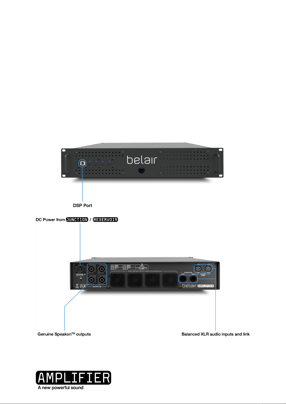
The belair AMPLIFIER module is a battery powered audio amplifier available in two
versions:
●F1K0 - Four 1000W outputs
●T2K0 - Two 2000W outputs
User Manual R1.0
3 / 30

SAFETY
General Safety Instructions
DO NOT place the equipment near heat sources. It is prohibited to place or operate the
equipment in an environment with flammable, explosive gas, or smoke.
DO NOT attempt to replace the internal battery or any other component of the
equipment by anyone other than authorised personnel. There are no end-user serviceable
components.
DO NOT operate in wet conditions. If the equipment becomes wet, please let the unit dry
completely before using.
ENSURE proper ventilation while in use and do not obstruct fan openings. Inadequate
ventilation may cause permanent damage to the equipment.
DO NOT move the unit while operating.
KEEP AWAY from children and pets.
DO NOT insert foreign objects into any ports or openings of the equipment.
If necessary, only dry powder fire extinguishers are suitable for the product.
USE ONLY the original cables designed for the equipment. Belair Technology SA are not
liable for damage caused by third party equipment that may render your warranty invalid.
Replacement cables are available by contacting sales@belairtechnology.com
REDUCE volume of the input source when changing configurations or loading a new
configuration.
Earthing
The AMPLIFIER chassis is electrically bonded to the chassis of the JUNCTION or
RESERVOIR powerstation used to power the module.
User Manual R1.0
4 / 30

When audio equipment is connected using the XLR inputs, the ground of the audio
equipment is bonded to the chassis of all belair products in use.
If the site installation requires grounding of the system to earth with a rod, the grounding
point for the belair TOWER should be the JUNCTION where an earthing stud is available on
the back panel.
User Manual R1.0
5 / 30

CARING FOR YOUR EQUIPMENT
Regularly clean the air intake filters at the rear of the module - the covers can be popped
off with a small flat screwdriver.
The front filters can be removed and cleaned by removing the top cover.
IN THE BOX
1
AMPLIFIER powerstation
2
DC Power Cable
3
USB-A to USB-B cable (for DSP)
4
Rack mounting screws
5
Rear support rails
6
User Manual
7
QC certificate
User Manual R1.0
6 / 30

INSTALLATION
It is recommended to install all belair equipment in suitable 19-inch enclosures. The rear
mounting kit should be used at all times to avoid stressing the front panel flanges.
User Manual R1.0
7 / 30

USING THE EQUIPMENT
Turning on
Connect the DC power cable between the JUNCTION and the AMPLIFIER with the
JUNCTION turned off. Fully turn the collar locking mechanism (clockwise) to ensure proper
contact.
Turn on the JUNCTION and any connected RESERVOIRS by pressing the central power
button.
Turn on the AMPLIFIER by pressing the central power button.
The channel monitor LEDs (on the left side of the front panel) will be lit immediately.
The power switch LED will be lit blue once the amplifier is ready - this takes around one
minute after connecting the power source.
If the amplifier is turned off and on again, it will again take around one minute for the
outputs to be active.
User Manual R1.0
8 / 30

Audio inputs and link
The XLR audio inputs are balanced +4dBu level and the source must be capable of
providing this level to guarantee the full rated power of the amplifier. If using a source with
RCA or jack output, we recommend using an Active Line Driver between the source and the
amplifier to boost the signal and convert the single-ended signal to a differential signal.
The audio link is passive with a 100Ω resistance between input and output so that even if
power is lost to one amplifier, downstream amplifiers will continue to receive the signal.
Note that daisy-chaining the audio between multiple amplifiers is only possible if using the
XLR inputs and not the USB source.
Speaker outputs
The speaker outputs are Speakon™ 4-pole connectors. Do not attempt to bridge the loads.
Connector
Wiring and associated
miniDSP channel
A
1+ / 1- : Output1
2+ / 2- : Not connected
B
1+ / 1- : Output2
2+ / 2- : Output1
C
1+ / 1- : Output3
2+ / 2- : Not connected
D
1+ / 1- : Output4
2+ / 2- : Output3
TAKE CARE WHEN USING 4 POLE SPEAKER CABLE -
SOME OUTPUTS HAVE TWO CHANNEL WIRED ON
ONE CONNECTOR!
User Manual R1.0
9 / 30

CONFIGURING THE DSP
The AMPLIFIER contains a digital signal processor (DSP) that is used to control the audio
signal from the source (e.g mixer) to the loudspeakers.
The DSP performs the following principal functions:
●Volume control
●Signal routing
●EQ
●Crossover
●Compression/Limiting
The DSP is configured using the miniDSP 2x4 HD app. This can be downloaded from
minidsp.com for MacOS and Windows at the following address:
https://www.minidsp.com/products/plugins/2x4-hd-plugins/2x4hd1-detail
This manual gives an overview of the most important functions of the DSP; a full
description can be found at the following address:
https://www.minidsp.com/products/minidsp-in-a-box/minidsp-2x4-hd
Connecting to the DSP
Install and open the miniDSP 2x4-HD app on your computer.
With the AMPLIFIER on, connect your computer to the front panel USB connector using the
supplied cable USB-A to USB-B cable.
Click ‘Connect’, located in the top right corner.
A dialog box will open to confirm successful connection.
If the below dialog box appears, ensure that all audio inputs are muted or very low before
selecting ‘Synchronize Config’ or ‘Restore Config’.
User Manual R1.0
10 / 30
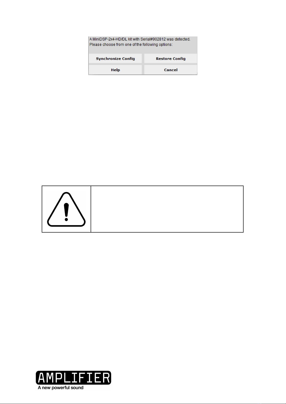
Synchronize Config: Download the currently selected configuration into the corresponding
configuration preset of the processor. After downloading the configuration data, the plugin
is in online mode and any changes to processing parameters will be downloaded
immediately in real time. That is, the user interface is now “live.”
Restore Config: Restore the data in the currently selected configuration to the factory
defaults. When using this option, any connected equipment should be muted or powered
off until you have set the configuration to a working state. Note that the configuration data
will be lost, so if needed, ensure that you have saved the configuration to a file prior to
using this option.
ALL SETTINGS COULD BE CHANGED WHICH COULD,
WITH AN AUDIO SIGNAL PRESENT, DAMAGE
HEARING AND EQUIPMENT!
Saving & Loading configurations
Configuration files can be saved and loaded using the top menu. Note that configurations
can not currently be downloaded from the DSP to a computer.
User Manual R1.0
11 / 30

Recommended workflow
Set limiters, then crossovers according to the speaker manufacturers’ recommendation.
Set inputs to 0dB and outputs to -72dB.
Send audio signal from source, confirm the signal is present on the input bar monitors.
Slowly turn up the output gain until the signal is audible and repeat for each channel. If
there is no audible signal even with an input signal, check all speaker cabling and DSP
routing.
User Manual R1.0
12 / 30

Inputs & Routing Tab
Set the ‘Inputs’ box to either ANALOG (to activate the AMPLIFIER XLR input connectors), or
USB to stream music digitally from your computer. Note that the USB input is intended for
initial setting of the DSP - long term stability is only guaranteed when using the ANALOG
input.
User Manual R1.0
13 / 30

The names of the input can be changed (for example to Left In and Right In). The outputs
can only be renamed from the Outputs Tab.
The ‘Routing’ section allows you to map any of the two input channels to any of the four
output channels to create various mono and stereo 2, 3 or 4 way systems.
User Manual R1.0
14 / 30

Outputs Tab
For each of the four channels there is the following functions:
●Volume fader
○Volume can also be changed by typing the desired value directly into the
dark grey box
●Parametric Equaliser (PEQ)
●Crossover
●Finite Impulse Response filter
Note that for the T2K0 AMPLIFIER; only Output1 and Output2 are used.
The names of the channels can be changed by double clicking on the name.
User Manual R1.0
15 / 30

Parametric EQ
This function can be used to fine tune the speaker within the audio environment.
User Manual R1.0
16 / 30
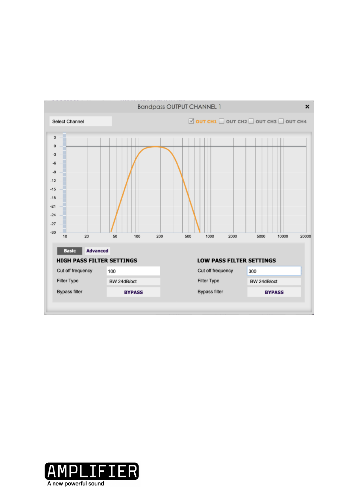
Crossovers
When using the AMPLIFIER, it is normal to use crossovers to send only suitable frequencies
to each speaker (e.g bass to subwoofer). Refer to your loudspeaker manufacturer or
supplier to correctly set crossovers and / or EQ.
User Manual R1.0
17 / 30
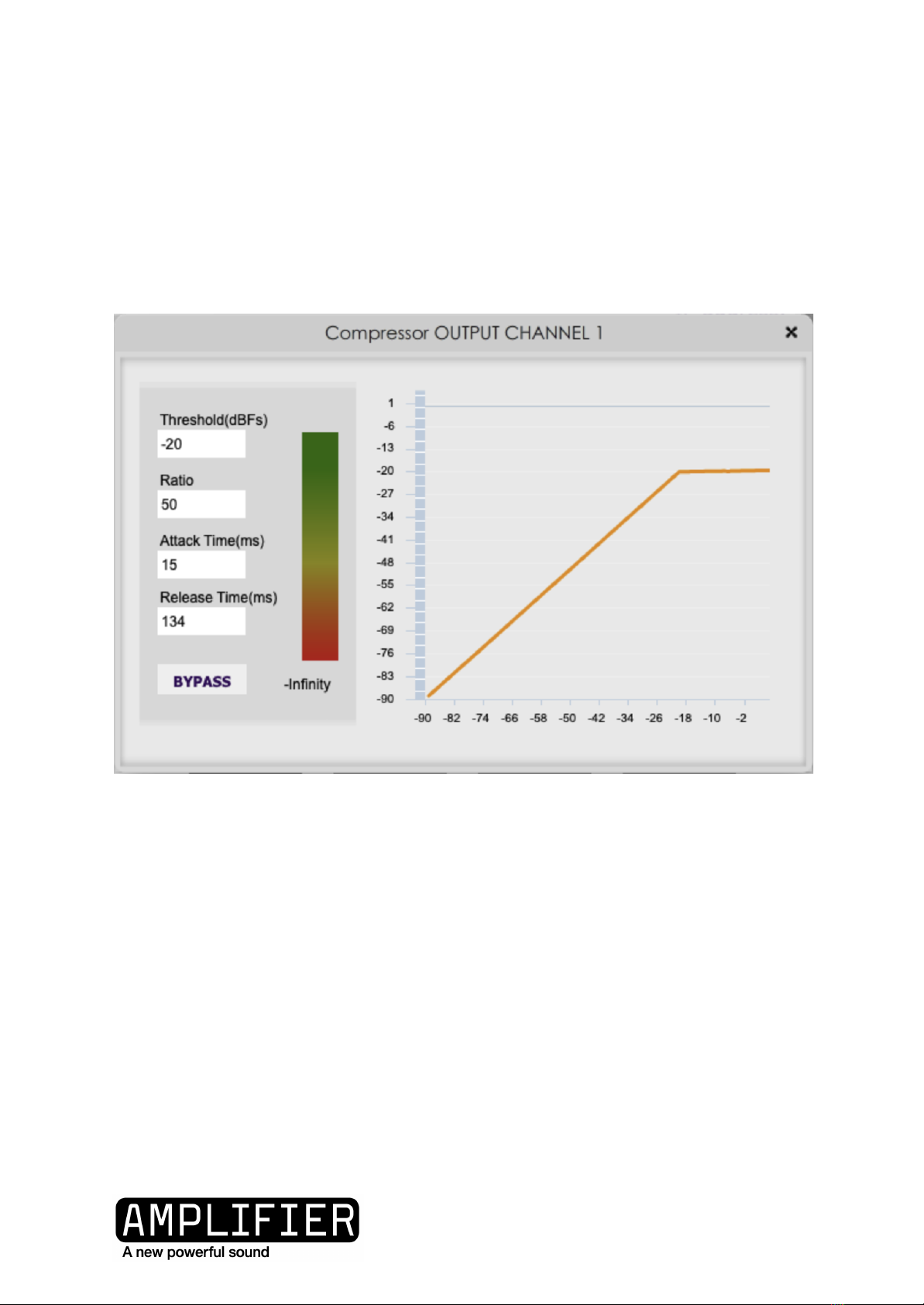
Compressor / Limiter
The compressor should always be activated and configured as a limited (Ratio=50, Attack
Time a minimum of 15ms) to protect your loudspeakers from being driven too hard which
will damage the driver.
An online calculator is available at www.belairtechnology.com/
I
User Manual R1.0
18 / 30

ALWAYS START WITH THE SOURCE VOLUME AT
ZERO AND SLOWLY INCREASE TO AVOID DAMAGING
HEARING AND LOUDSPEAKERS)
WHEN SWITCHING BETWEEN CONFIGURATIONS OR
LOADING NEW CONFIGURATIONS IT IS STRONGLY
ADVISED TO REDUCE THE VOLUME OF THE INPUT
SOURCE (EG REDUCE THE MIXER OUTPUT VOLUME)
TO AVOID DAMAGING HEARING AND
LOUDSPEAKERS)
LED CHANNEL MONITORS
The button below each LED mutes that channel.
Charge
Front Panel
100%
50%-75%
25%-50%
User Manual R1.0
19 / 30

0%-25%
User Manual R1.0
20 / 30
This manual suits for next models
1
Table of contents


