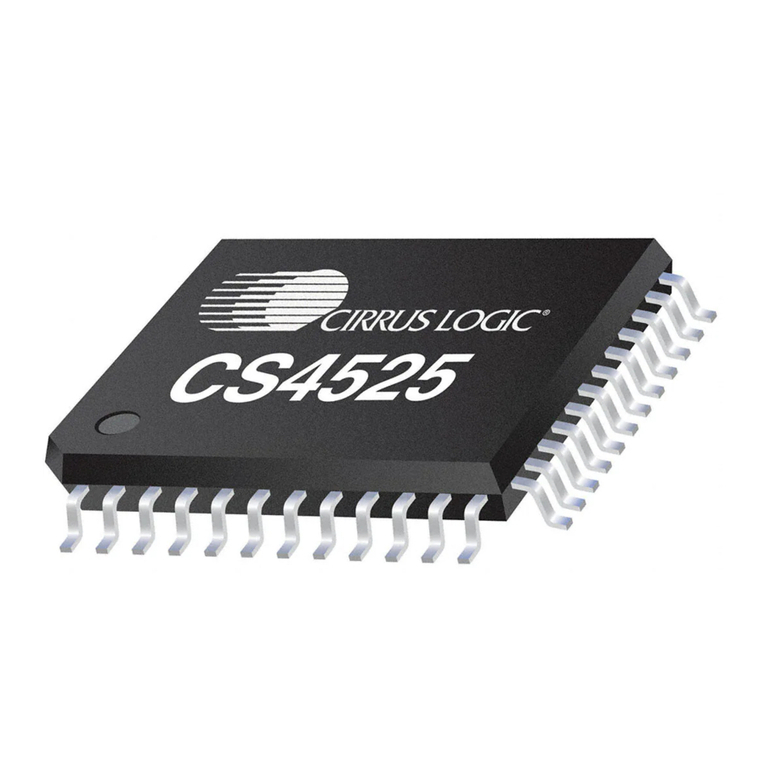
Cirrus Logic CS4525 User manual

Copyright ©Cirrus Logic, Inc. 2007
(All Rights Reserved)
http://www.cirrus.com
Preliminary Product Information This document contains information for a new product.
Cirrus Logic reserves the right to modify this product without notice.
30 W Digital Audio Amplifier with Integrated ADC
Digital Amplifier Features
Fully Integrated Power MOSFETs
No Heatsink Required
– Programmable Power Foldback on
Thermal Warning
– High Efficiency
> 100 dB Dynamic Range
< 0.1% THD+N @ 1 W
Configurable Outputs (10% THD+N)
– 1 x 30 W into 4 Ω, Parallel Full-Bridge
– 2 x 15 W into 8 Ω, Full-Bridge
– 2 x 7 W into 4 Ω, Half-Bridge + 1 x 15 W
into 8 Ω, Full-Bridge
Built-In Protection with Error Reporting
– Overcurrent/Undervoltage/Thermal
Overload Shutdown
– Thermal Warning Reporting
PWM Popguard®for Half-Bridge Mode
Click-Free Start-Up
Programmable Channel Delay for System
Noise & Radiated Emissions Management
ADC Features
Stereo, 24-bit, 48 kHz Conversion
Multi-bit Architecture
95 dB Dynamic Range (A-wtd)
-86 dB THD+N
Supports 2 Vrms Input with Passive
Components
System Features
Asynchronous 2-Channel Digital Serial Port
32 kHz to 96 kHz Input Sample Rates
Operation with On-Chip Oscillator Driver or
Applied SYS_CLK at 18.432, 24.576 or
27.000 MHz
Integrated Sample Rate Converter (SRC)
– Eliminates Clock-Jitter Effects
– Input Sample Rate Independent Operation
– Simplifies System Integration
Spread Spectrum PWM Modulation
– Reduces EMI Radiated Energy
Low Quiescent Current
(Features continued on page 2)
VP Amplifier
Out 1
Amplifier
Out 2
PGND
Amplifier
Out 3
Amplifier
Out 4
Stereo
Analog In
PWM Modulator
Output 2
PWM Modulator
Output 1
Gate
Drive
Gate
Drive
Gate
Drive
Gate
Drive
Multi-bit ΔΣ
Modulator
with
Integrated
Sample Rate
Converter
Audio
Processing
Parametric EQ
High-Pass
Bass/Treble
Adaptive
2-Ch Mixer
2.1 Bass Mgr
Linkwitz-Riley
Crossover
De-Emphasis
Serial Audio
Clocks & Data
Serial Audio
Data I/O
Serial Audio
Clocks & Data
Serial Audio Input Port
Multi-bit ΔΣ ADC
Volume
Crystal Driver
I/O
System Clock
Crystal Oscillator Driver
Register /Hardware
Configuration
I²C or Hardware
Configuration
Reset
Interrupt
Error Protection
Thermal Warning Over Current
Thermal Feedback Under Voltage
HP Detect/Mute
PWM
2.5 V to 5 V 8 V to 18 V
Auxiliary Serial Port
Serial Audio
Delay Interface
Loudness
Compensation
NOVEMBER '07
DS726PP2
CS4525

2DS726PP2
CS4525
Software Mode System Features
Digital Audio Processing
– 5 Programmable Parametric EQ Filters
– Selectable High-Pass Filter
– Bass/Treble Tone Control
– Adaptive Loudness Compensation
– 2-Channel Mixer
– 2.1 Bass Management
– 24 dB/octave Linkwitz-Riley Crossover
Filters
– De-emphasis Filter
Selectable Serial Audio Interface Formats
– Left-Justified up to 24-bit
– I²S up to 24-bit
– Right-Justified 16-, 18-, 20-, 24-bits
Digital Serial Connection to Additional CS4525
or DACs for Subwoofer
Digital Interface to External Lip-Sync Delay
PWM Switch Rate Shifting Eliminates AM
Frequency Interference
Digital Volume Control with Soft ramp
– +24 to -103 dB in 0.5 dB steps
Programmable Peak Detect and Limiter
2-Channel Logic-Level PWM Output
– Programmable Channel Mapping
– Can Drive an External PWM Amplifier,
Headphone Amplifier, or Line-Out Amplifier
– Integrated Headphone Detection
Flexible Power Output Configurations
Thermal Foldback for Interruption-Free
Power-Stage Protection
– Supports Internal and External Power
Stages
Operation from On-Chip Oscillator Driver or
Applied Systems Clock
Supports I²C®Host Control Interface
Hardware Mode System Features
2-Channel Stereo Full-Bridge Power Outputs
Analog and Digital Inputs
I²S and Left-Justified Serial Input Formats
Thermal Foldback for Interruption-Free
Protection of Internal Power Stage
Operation from Applied Systems Clock
External Mute Input
Common Applications
Integrated Digital TV’s
Flat Panel TV Monitors
Computer/TV Monitors
Mini/Micro Shelf Systems
Digital Powered Speakers
Portable Docking Stations
Computer Desktop Audio
General Description
The CS4525 is a stereo analog or digital input PWM
high efficiency Class D amplifier audio system with an
integrated stereo analog-to-digital (A/D) converter. The
stereo power amplifiers can deliver up to 15 W per
channel into 8 Ω speakers from a small space-saving
48-pin QFN package. The PWM amplifier can achieve
greater than 85% efficiency. The package is thermally
enhanced for optimal heat dissipation which eliminates
the need for a heatsink.
The power stage outputs can be configured as two full-
bridge channels for 2 x 15 W operation, two half-bridge
channels and one full-bridge channel for
2 x 7 W + 1 x 15 W operation, or one parallel full-bridge
channel for 1 x 30 W operation. The CS4525 integrates
on-chip over-current, under-voltage, and over-tempera-
ture protection and error reporting as well as a thermal
warning indicator and programmable foldback of the
output power to allow cooling.
The main digital serial port on the CS4525 can support
asynchronous operation with the integrated on-chip
sample rate converter (SRC) which eases system inte-
gration. The SRC allows for a fixed PWM switching
frequency regardless of incoming sample rate as well
as optimal clocking for the A/D modulators.
An on-chip oscillator driver eliminates the need for an
external crystal oscillator circuit, reducing overall design
cost and conserving circuit board space. The CS4525
automatically uses the on-chip oscillator driver in the
absence of an applied master clock.
The CS4525 is available in a 48-pin QFN package in
Commercial grade (-10° to +70° C). The CRD4525-Q1
4-layer, 1 oz. copper and CRD4525-D1 2-layer, 1 oz.
copper customer reference designs are also available.
Please refer to “Ordering Information” on page 97 for
complete ordering information.

DS726PP2 3
CS4525
TABLE OF CONTENTS
1. PIN DESCRIPTIONS - SOFTWARE MODE .......................................................................................... 8
2. PIN DESCRIPTIONS - HARDWARE MODE ....................................................................................... 10
2.1 Digital I/O Pin Characteristics ........................................................................................................ 12
3. TYPICAL CONNECTION DIAGRAMS .................................................................................................13
4. TYPICAL SYSTEM CONFIGURATION DIAGRAMS ........................................................................... 15
5. CHARACTERISTICS AND SPECIFICATIONS .................................................................................... 18
6. APPLICATIONS ................................................................................................................................... 26
6.1 Software Mode ............................................................................................................................... 26
6.1.1 System Clocking ................................................................................................................... 26
6.1.1.1 SYS_CLK Input Clock Mode .................................................................................... 26
6.1.1.2 Crystal Oscillator Mode ............................................................................................ 27
6.1.2 Power-Up and Power-Down ................................................................................................. 28
6.1.2.1 Recommended Power-Up Sequence ....................................................................... 28
6.1.2.2 Recommended Power-Down Sequence .................................................................. 28
6.1.3 Input Source Selection .......................................................................................................... 29
6.1.4 Digital Sound Processing ...................................................................................................... 29
6.1.4.1 Pre-Scaler ................................................................................................................. 30
6.1.4.2 Digital Signal Processing High-Pass Filter ............................................................... 30
6.1.4.3 Channel Mixer ..........................................................................................................30
6.1.4.4 De-Emphasis ............................................................................................................31
6.1.4.5 Tone Control ............................................................................................................. 31
6.1.4.6 Parametric EQ ..........................................................................................................33
6.1.4.7 Adaptive Loudness Compensation ........................................................................... 34
6.1.4.8 Bass Management .................................................................................................... 35
6.1.4.9 Volume and Muting Control ...................................................................................... 36
6.1.4.10 Peak Signal Limiter ................................................................................................. 37
6.1.4.11 Thermal Limiter .......................................................................................................39
6.1.4.12 Thermal Foldback ................................................................................................... 40
6.1.4.13 2-Way Crossover & Sensitivity Control ................................................................... 41
6.1.5 Auxiliary Serial Output .......................................................................................................... 43
6.1.6 Serial Audio Delay & Warning Input Port .............................................................................. 44
6.1.6.1 Serial Audio Delay Interface ..................................................................................... 44
6.1.6.2 External Warning Input Port ..................................................................................... 44
6.1.7 Powered PWM Outputs ........................................................................................................ 45
6.1.7.1 Output Channel Configurations ................................................................................ 45
6.1.7.2 PWM Popguard Transient Control ............................................................................ 45
6.1.8 Logic-Level PWM Outputs .................................................................................................... 46
6.1.8.1 Recommended PWM_SIG Power-Up Sequence for an External PWM Amplifier .... 47
6.1.8.2 Recommended PWM_SIG Power-Down Sequence for an External PWM Amplifier 47
6.1.8.3 Recommended PWM_SIG Power-Up Sequence for Headphone & Line-Out .......... 48
6.1.8.4 Recommended PWM_SIG Power-Down Sequence for Headphone & Line-Out ..... 48
6.1.8.5 PWM_SIG Logic-Level Output Configurations ......................................................... 49
6.1.9 PWM Modulator Configuration ..............................................................................................50
6.1.9.1 PWM Channel Delay ................................................................................................ 50
6.1.9.2 PWM AM Frequency Shift ........................................................................................ 51
6.1.10 Headphone Detection & Hardware Mute Input ................................................................... 51
6.1.11 Interrupt Reporting .............................................................................................................. 53
6.1.12 Automatic Power Stage Shut-Down ................................................................................... 53
6.2 Hardware Mode ............................................................................................................................. 54
6.2.1 System Clocking ................................................................................................................... 54
6.2.2 Power-Up and Power-Down ................................................................................................. 54
6.2.2.1 Recommended Power-Up Sequence ....................................................................... 54

4DS726PP2
CS4525
6.2.2.2 Recommended Power-Down Sequence .................................................................. 55
6.2.3 Input Source Selection .......................................................................................................... 55
6.2.4 PWM Channel Delay ............................................................................................................ 55
6.2.5 Digital Signal Flow ................................................................................................................ 56
6.2.5.1 High-Pass Filter ........................................................................................................ 56
6.2.5.2 Mute Control ............................................................................................................. 56
6.2.5.3 Warning and Error Reporting .................................................................................... 56
6.2.6 Thermal Foldback ................................................................................................................. 57
6.2.7 Automatic Power Stage Shut-Down ..................................................................................... 58
6.3 PWM Modulators and Sample Rate Converters ............................................................................ 58
6.4 Output Filters ................................................................................................................................. 59
6.4.1 Half-Bridge Output Filter ....................................................................................................... 59
6.4.2 Full-Bridge Output Filter (Stereo or Parallel) ........................................................................ 60
6.5 Analog Inputs ................................................................................................................................. 61
6.6 Serial Audio Interfaces ................................................................................................................... 62
6.6.1 I²S Data Format .................................................................................................................... 62
6.6.2 Left-Justified Data Format .................................................................................................... 62
6.6.3 Right-Justified Data Format .................................................................................................. 63
6.7 Integrated VD Regulator ................................................................................................................ 63
6.8 I²C Control Port Description and Timing ........................................................................................ 64
7. PCB LAYOUT CONSIDERATIONS ..................................................................................................... 65
7.1 Power Supply, Grounding .............................................................................................................. 65
7.2 QFN Thermal Pad .......................................................................................................................... 65
8. REGISTER QUICK REFERENCE ........................................................................................................ 66
9. REGISTER DESCRIPTIONS ................................................................................................................ 69
9.1 Clock Configuration (Address 01h) ................................................................................................ 69
9.1.1 SYS_CLK Output Enable (EnSysClk) ................................................................................... 69
9.1.2 SYS_CLK Output Divider (DivSysClk) .................................................................................. 69
9.1.3 Clock Frequency (ClkFreq[1:0]) ............................................................................................ 69
9.1.4 HP_Detect/Mute Pin Active Logic Level (HP/MutePol) ......................................................... 70
9.1.5 HP_Detect/Mute Pin Mode (HP/Mute) .................................................................................. 70
9.1.6 Modulator Phase Shifting (PhaseShift) ................................................................................. 70
9.1.7 AM Frequency Shifting (FreqShift) ....................................................................................... 70
9.2 Input Configuration (Address 02h) ................................................................................................. 71
9.2.1 Input Source Selection (ADC/SP) .........................................................................................71
9.2.2 ADC High-Pass Filter Enable (EnAnHPF) ............................................................................ 71
9.2.3 Serial Port Sample Rate (SPRate[1:0]) - Read Only ............................................................ 71
9.2.4 Input Serial Port Digital Interface Format (DIF [2:0]) ............................................................ 71
9.3 AUX Port Configuration (Address 03h) .......................................................................................... 72
9.3.1 Enable Aux Serial Port (EnAuxPort) ..................................................................................... 72
9.3.2 Delay & Warning Port Configuration (DlyPortCfg[1:0]) ......................................................... 72
9.3.3 Aux/Delay Serial Port Digital Interface Format (AuxI²S/LJ) .................................................. 72
9.3.4 Aux Serial Port Right Channel Data Select (RChDSel[1:0]) ................................................. 72
9.3.5 Aux Serial Port Left Channel Data Select (LChDSel[1:0]) .................................................... 73
9.4 Output Configuration (Address 04h) ............................................................................................. 73
9.4.1 Output Configuration (OutputCfg[1:0]) .................................................................................. 73
9.4.2 PWM Signals Output Data Select (PWMDSel[1:0]) .............................................................. 73
9.4.3 Channel Delay Settings (OutputDly[3:0]) .............................................................................. 73
9.5 Foldback and Ramp Configuration (Address 05h) ......................................................................... 74
9.5.1 Select VP Level (SelectVP) .................................................................................................. 74
9.5.2 Enable Thermal Foldback (EnTherm) ................................................................................... 74
9.5.3 Lock Foldback Adjust (LockAdj) ...........................................................................................74
9.5.4 Foldback Attack Delay (AttackDly[1:0]) ................................................................................ 75
9.5.5 Enable Foldback Floor (EnFloor) ..........................................................................................75

DS726PP2 5
CS4525
9.5.6 Ramp Speed (RmpSpd[1:0]) ................................................................................................75
9.6 Mixer / Pre-Scale Configuration (Address 06h) .............................................................................75
9.6.1 Pre-Scale Attenuation (PreScale[2:0]) .................................................................................. 75
9.6.2 Right Channel Mixer (RChMix[1:0]) ...................................................................................... 76
9.6.3 Left Channel Mixer (LChMix[1:0]) .........................................................................................76
9.7 Tone Configuration (Address 07h) ................................................................................................. 76
9.7.1 De-Emphasis Control (DeEmph) .......................................................................................... 76
9.7.2 Adaptive Loudness Compensation Control (Loudness) ....................................................... 76
9.7.3 Digital Signal Processing High-Pass Filter (EnDigHPF) ....................................................... 77
9.7.4 Treble Corner Frequency (TrebFc[1:0]) ................................................................................ 77
9.7.5 Bass Corner Frequency (BassFc[1:0]) ................................................................................. 77
9.7.6 Tone Control Enable (EnToneCtrl) ....................................................................................... 77
9.8 Tone Control (Address 08h) ........................................................................................................... 78
9.8.1 Treble Gain Level (Treb[3:0]) ................................................................................................ 78
9.8.2 Bass Gain Level (Bass[3:0]) ................................................................................................. 78
9.9 2.1 Bass Manager/Parametric EQ Control (Address 09h) ............................................................. 78
9.9.1 Freeze Controls (Freeze) ...................................................................................................... 78
9.9.2 Hi-Z PWM_SIG Outputs (HiZPSig) ....................................................................................... 79
9.9.3 Bass Cross-Over Frequency (BassMgr[2:0]) ........................................................................ 79
9.9.4 Enable Channel B Parametric EQ (EnChBPEq) ................................................................... 79
9.9.5 Enable Channel A Parametric EQ (EnChAPEq) ................................................................... 79
9.10 Volume and 2-Way Cross-Over Configuration (Address 55h) ..................................................... 80
9.10.1 Soft Ramp and Zero Cross Control (SZCMode[1:0]) .......................................................... 80
9.10.2 Enable 50% Duty Cycle for Mute Condition (Mute50/50) ................................................... 80
9.10.3 Auto-Mute (AutoMute) ........................................................................................................ 80
9.10.4 Enable 2-Way Crossover (En2Way) ................................................................................... 81
9.10.5 2-Way Cross-Over Frequency (2WayFreq[2:0]) ................................................................. 81
9.11 Channel A & B: 2-Way Sensitivity Control (Address 56h) ............................................................ 81
9.11.1 Channel A and Channel B Low-Pass Sensitivity Adjust (LowPass[3:0]) ............................ 81
9.11.2 Channel A and Channel B High-Pass Sensitivity Adjust (HighPass[3:0]) ........................... 82
9.12 Master Volume Control (Address 57h) ........................................................................................ 82
9.12.1 Master Volume Control (MVol[7:0]) .................................................................................... 82
9.13 Channel A and B Volume Control (Address 58h & 59h) .............................................................. 83
9.13.1 Channel X Volume Control (ChXVol[7:0]) ........................................................................... 83
9.14 Sub Channel Volume Control (Address 5Ah) .............................................................................. 83
9.14.1 Sub Channel Volume Control (SubVol[7:0]) ....................................................................... 83
9.15 Mute/Invert Control (Address 5Bh) .............................................................................................. 84
9.15.1 ADC Invert Signal Polarity (InvADC) .................................................................................. 84
9.15.2 Invert Channel PWM Signal Polarity (InvChX) ................................................................... 84
9.15.3 Invert Sub PWM Signal Polarity (InvSub) ........................................................................... 84
9.15.4 ADC Channel Mute (MuteADC) .......................................................................................... 84
9.15.5 Independent Channel A & B Mute (MuteChX) .................................................................... 84
9.15.6 Sub Channel Mute (MuteSub) ............................................................................................ 85
9.16 Limiter Configuration 1 (Address 5Ch) ......................................................................................... 85
9.16.1 Maximum Threshold (Max[2:0]) .......................................................................................... 85
9.16.2 Minimum Threshold (Min[2:0]) ............................................................................................85
9.16.3 Peak Signal Limit All Channels (LimitAll) ............................................................................ 86
9.16.4 Peak Detect and Limiter Enable (EnLimiter) ....................................................................... 86
9.17 Limiter Configuration 2 (Address 5Dh) ......................................................................................... 87
9.17.1 Limiter Release Rate (RRate[5:0]) ...................................................................................... 87
9.18 Limiter Configuration 3 (Address 5Eh) ......................................................................................... 87
9.18.1 Enable Thermal Limiter (EnThLim) ..................................................................................... 87
9.18.2 Limiter Attack Rate (ARate[5:0]) ......................................................................................... 87
9.19 Power Control (Address 5Fh) ...................................................................................................... 88

6DS726PP2
CS4525
9.19.1 Automatic Power Stage Retry (AutoRetry) ......................................................................... 88
9.19.2 Enable Over-Current Protection (EnOCProt) ...................................................................... 88
9.19.3 Select VD Level (SelectVD) ................................................................................................ 88
9.19.4 Power Down ADC (PDnADC) ............................................................................................. 88
9.19.5 Power Down PWM Power Output X (PDnOutX) ................................................................. 88
9.19.6 Power Down (PDnAll) ......................................................................................................... 89
9.20 Interrupt (Address 60h) ............................................................................................................... 89
9.20.1 SRC Lock State Transition Interrupt (SRCLock) ................................................................ 89
9.20.2 ADC Overflow Interrupt (ADCOvfl) ..................................................................................... 90
9.20.3 Channel Overflow Interrupt (ChOvfl) .................................................................................. 90
9.20.4 Amplifier Error Interrupt Bit (AmpErr) ..................................................................................90
9.20.5 Mask for SRC State (SRCLockM) ...................................................................................... 91
9.20.6 Mask for ADC Overflow (ADCOvflM) .................................................................................. 91
9.20.7 Mask for Channel X and Sub Overflow (ChOvflM) ............................................................. 91
9.20.8 Mask for Amplifier Error (AmpErrM) ................................................................................... 92
9.21 Interrupt Status (Address 61h) - Read Only ................................................................................. 92
9.21.1 SRC State Transition (SRCLockSt) .................................................................................... 92
9.21.2 ADC Overflow (ADCOvflSt) ................................................................................................92
9.21.3 Sub Overflow (SubOvflSt) ................................................................................................... 92
9.21.4 Channel X Overflow (ChXOvflSt) ........................................................................................ 93
9.21.5 Ramp-Up Cycle Complete (RampDone) ............................................................................ 93
9.22 Amplifier Error Status (Address 62h) - Read Only ....................................................................... 93
9.22.1 Over-Current Detected On Channel X (OverCurrX) ........................................................... 93
9.22.2 External Amplifier State (ExtAmpSt) ................................................................................... 93
9.22.3 Under Voltage / Thermal Error State (UVTE[1:0]) .............................................................. 94
9.23 Device I.D. and Revision (Address 63h) - Read Only .................................................................. 94
9.23.1 Device Identification (DeviceID[4:0]) ...................................................................................94
9.23.2 Device Revision (RevID[2:0]) .............................................................................................. 94
10. PARAMETER DEFINITIONS .............................................................................................................. 95
11. REFERENCES .................................................................................................................................... 95
12. PACKAGE DIMENSIONS .................................................................................................................. 96
13. THERMAL CHARACTERISTICS ....................................................................................................... 97
13.1 Thermal Flag ................................................................................................................................ 97
14. ORDERING INFORMATION .............................................................................................................. 97
15. REVISION HISTORY .......................................................................................................................... 98
LIST OF FIGURES
Figure 1.Typical Connection Diagram - Software Mode ........................................................................... 13
Figure 2.Typical Connection Diagram - Hardware Mode .......................................................................... 14
Figure 3.Typical System Configuration 1 .................................................................................................. 15
Figure 4.Typical System Configuration 2 .................................................................................................. 15
Figure 5.Typical System Configuration 3 .................................................................................................. 16
Figure 6.Typical System Configuration 4 .................................................................................................. 17
Figure 7.Serial Audio Input Port Timing .................................................................................................... 21
Figure 8.AUX Serial Port Interface Master Mode Timing ..........................................................................22
Figure 9.SYS_CLK Timing from Reset ..................................................................................................... 23
Figure 10.PWM_SIGX Timing ................................................................................................................... 23
Figure 11.Control Port Timing - I²C ........................................................................................................... 24
Figure 12.Typical SYS_CLK Input Clocking Configuration ....................................................................... 26
Figure 13.Typical Crystal Oscillator Clocking Configuration ..................................................................... 27
Figure 14.Digital Signal Flow .................................................................................................................... 29
Figure 15.De-Emphasis Filter ................................................................................................................... 31
Figure 16.Bi-Quad Filter Architecture ........................................................................................................ 33

DS726PP2 7
CS4525
Figure 17.Peak Signal Detection & Limiting .............................................................................................. 37
Figure 18.Foldback Process ..................................................................................................................... 40
Figure 19.Popguard Connection Diagram ................................................................................................. 46
Figure 20.2-Channel Full-Bridge PWM Output Delay ...............................................................................50
Figure 21.3-Channel PWM Output Delay .................................................................................................. 50
Figure 22.Typical SYS_CLK Input Clocking Configuration ....................................................................... 54
Figure 23.Hardware Mode PWM Output Delay ......................................................................................... 55
Figure 24.Hardware Mode Digital Signal Flow .......................................................................................... 56
Figure 25.Foldback Process ..................................................................................................................... 57
Figure 26.Output Filter - Half-Bridge ......................................................................................................... 59
Figure 27.Output Filter - Full-Bridge .......................................................................................................... 60
Figure 28.Recommended Unity Gain Input Filter ...................................................................................... 61
Figure 29.Recommended 2 VRMS Input Filter ........................................................................................... 61
Figure 30.I²S Serial Audio Formats ........................................................................................................... 62
Figure 31.Left-Justified Serial Audio Formats ........................................................................................... 62
Figure 32.Right-Justified Serial Audio Formats ......................................................................................... 63
Figure 33.Control Port Timing, I²C Write ................................................................................................... 64
Figure 34.Control Port Timing, I²C Read ................................................................................................... 64
LIST OF TABLES
Table 1. I/O Power Rails ........................................................................................................................... 12
Table 2. Bass Shelving Filter Corner Frequencies .................................................................................... 31
Table 3. Treble Shelving Filter Corner Frequencies ................................................................................. 32
Table 4. Bass Management Cross-Over Frequencies .............................................................................. 35
Table 5. 2-Way Cross-Over Frequencies .................................................................................................. 41
Table 6. Auxiliary Serial Port Data Output ................................................................................................ 43
Table 7. Nominal Switching Frequencies of the Auxiliary Serial Output ................................................... 43
Table 8. PWM Power Output Configurations ............................................................................................ 45
Table 9. Typical Ramp Times for Various VP Voltages ............................................................................46
Table 10. PWM Logic-Level Output Configurations .................................................................................. 49
Table 11. PWM Output Switching Rates and Quantization Levels ........................................................... 51
Table 12. Output of PWM_SIG Outputs .................................................................................................... 52
Table 13. SYS_CLOCK Frequency Selection ........................................................................................... 54
Table 14. Input Source Selection .............................................................................................................. 55
Table 15. Serial Audio Interface Format Selection .................................................................................... 55
Table 16. Thermal Foldback Enable Selection ......................................................................................... 57
Table 17. PWM Output Switching Rates and Quantization Levels ........................................................... 58
Table 18. Low-Pass Filter Components - Half-Bridge ............................................................................... 59
Table 19. DC-Blocking Capacitors Values - Half-Bridge ........................................................................... 59
Table 20. Low-Pass Filter Components - Full-Bridge ............................................................................... 60
Table 21. Power Supply Configuration and Settings ................................................................................. 63

8DS726PP2
CS4525
1. PIN DESCRIPTIONS - SOFTWARE MODE
Pin Name Pin # Pin Description
INT 1Interrupt (Output) - Indicates an interrupt condition has occurred.
SCL 2 Serial Control Port Clock (Input) - Serial clock for the I²C control port.
SDA 3 Serial Control Data (Input/Output) - Bi-directional data I/O for the I²C control port.
LRCK 4 Left Right Clock (Input) - Determines which channel, Left or Right, is currently active on the serial
audio data line.
SCLK 5 Serial Clock (Input)- Serial bit clock for the serial audio interface.
SDIN 6 Serial Audio Data Input (Input) - Input for two’s complement serial audio data.
HP_DETECT/
MUTE 7Headphone Detect / Mute (Input) - Headphone detection or mute input signal as configured via the
I²C control port.
RST 8
Reset (Input) - The device enters a low power mode and all internal registers are reset to their
default settings when this pin is driven low.
Top-Down (Through Package) View
48-Pin QFN Package
12
7
6
5
4
3
2
1
11
10
9
8
25
30
31
32
33
34
35
36
26
27
28
29
1413 15 16 17 18 19 20 21 22 23 24
4748 46 45 44 43 42 41 40 39 38 37
INT
SCL
SDA
LRCK
SCLK
SDIN
HP_DETECT/MUTE
RST
LVD
DGND
VD_REG
VD
VP
OUT1
PGND
PGND
OUT2
VP
VP
OUT3
PGND
PGND
OUT4
VP
VA_REG
AGND
FILT+
VQ
AFILTL
AFILTR
AINL
AINR
OCREF
PGND
PGND
RAMP_CAP
XTI
XTO
SYS_CLK
AUX_LRCK/AD0
AUX_SCLK
AUX_SDOUT
DLY_SDIN/EX_TWR
DLY_SDOUT
PWM_SIG1
PWM_SIG2
PGND
PGND
Thermal Pad

DS726PP2 9
CS4525
LVD 9 VD Voltage Level Indicator (Input) - Identifies the voltage level attached to VD. When applying
5.0 V to VD, LVD must be connected to VD. When applying 2.5 V or 3.3 V to VD, LVD must be
DGND.
DGND 10 Digital Ground (Input) - Ground for the internal logic and digital I/O.
VD_REG 11 Core Logic Power (Output) - Internally generated low voltage power supply for digital logic.
VD 12 Power (Input) - Positive power supply for the internal regulators and digital I/O.
VA_REG 13 Analog Power (Output) - Internally generated positive power for the analog section and I/O.
AGND 14 Analog Ground (Input) - Ground reference for the internal analog section and I/O.
FILT+ 15 Positive Voltage Reference (Output) - Positive reference voltage for the internal ADC sampling
circuits.
VQ 16 Common Mode Voltage (Output)-Filter connection for internal common mode voltage.
AFILTL
AFILTR 17
18 Antialias Filter Connection (Output) - Antialias filter connection for ADC inputs.
AINL
AINR 19
20 Analog Input (Input)-The full-scale input level is specified in the ADC Analog Characteristics
specification table.
OCREF 21 Over Current Reference Setting (Input) - Sets the reference for over current detection.
PGND
22,23
27,28
33,34
37,38
Power Ground (Input) - Ground for the individual output power half-bridge devices.
RAMP_CAP 24 Output Ramp Capacitor (Input) - Used by the PWM Popguard Transient Control to suppress the
initial pop in half-bridge-configured outputs.
VP 25,30,
31,36 High Voltage Power (Input) - High voltage power supply for the individual half-bridge devices.
OUT4
OUT3
OUT2
OUT1
26
29
32
35
PWM Output (Output) - Amplified PWM power outputs.
PWM_SIG2
PWM_SIG1 39
40 Logic Level PWM Output (Output) - Logic Level PWM switching signals.
DLY_SDOUT 41 Delay Serial Audio Data Out (Output) - Output for two’s complement serial audio data.
DLY_SDIN/
EX_TWR 42 Delay Serial Audio Data Input (Input) - Input for two’s complement serial audio data.
External Thermal Warning (Input) - Input for an external thermal warning signal. Configurable via
the I²C control port.
AUX_SDOUT 43 Auxiliary Port Serial Audio Data Out (Output) - Output for two’s complement auxiliary port serial
data.
AUX_SCLK 44 Auxiliary Port Serial Clock (Output) - Serial clock for the auxiliary port serial interface.
AUX_LRCK/
AD0 45 Auxiliary Port Left Right Clock (Output) - Determines which channel, Left or Right, is currently
active on the serial audio data line.
AD0 (Input) - Sets the LSB of the I²C device address. Sensed on the release of RST.
SYS_CLK 46 System Clock (Input/Output) -Clock source for the internal logic, processing, and modulators. This
pin should be connected to through a 10kΩto ground when unused.
XTO 47 Crystal Oscillator Output (Output) - Crystal oscillator driver output.
XTI 48 Crystal Oscillator Input (Input) - Crystal oscillator driver input.
Thermal Pad - Thermal Pad - Thermal relief pad for optimized heat dissipation. See “QFN Thermal Pad” on
page 65 for more information.

10 DS726PP2
CS4525
2. PIN DESCRIPTIONS - HARDWARE MODE
Pin Name Pin # Pin Description
CLK_FREQ0
CLK_FREQ1 1
2Clock Frequency (Input) - Determines the frequency of the clock expected to be driven into the
SYS_CLK pin.
ADC/SP 3ADC/Serial Port (Input) - Selects between the Analog to Digital Converter and the Serial Port for
audio input. Selects the ADC when high or the serial port when low.
LRCK 4 Left Right Clock (Input) - Determines which channel, Left or Right, is currently active on the serial
audio data line.
SCLK 5 Serial Clock (Input)-Serial bit clock for the serial audio interface.
SDIN 6 Serial Audio Data Input (Input) - Input for two’s complement serial audio data.
MUTE 7
Mute (Input) - The PWM outputs will output silence as a 50% duty cycle signal when this pin is
driven low.
RST 8
Reset (Input) - The device enters a low power mode and all internal registers are reset to their
default settings when this pin is driven low.
Top-Down (Through Package) View
48-Pin QFN Package
12
7
6
5
4
3
2
1
11
10
9
8
25
30
31
32
33
34
35
36
26
27
28
29
1413 15 16 17 18 19 20 21 22 23 24
4748 46 45 44 43 42 41 40 39 38 37
CLK_FREQ0
CLK_FREQ1
ADC/SP
LRCK
SCLK
SDIN
MUTE
RST
LVD
DGND
VD_REG
VD
VP
OUT1
PGND
PGND
OUT2
VP
VP
OUT3
PGND
PGND
OUT4
VP
VA_REG
AGND
FILT+
VQ
AFILTL
AFILTR
AINL
AINR
OCREF
PGND
PGND
RAMP_CAP
TSTI
TSTO
SYS_CLK
I2S/LJ
EN_TFB
ERROC
ERRUVTE
TWR
TSTO
TSTO
PGND
PGND
Thermal Pad

DS726PP2 11
CS4525
LVD 9 VD Voltage Level Indicator (Input) - Identifies the voltage level attached to VD. When applying
5.0 V to VD, LVD must be connected to VD. When applying 2.5 V or 3.3 V to VD, LVD must be con-
nected to DGND.
DGND 10 Digital Ground (Input) - Ground for the internal logic and I/O.
VD_REG 11 Core Logic Power (Output) - Internally generated low voltage power supply for digital logic.
VD 12 Digital Power (Input) - Positive power supply for the internal regulators and digital I/O.
VA_REG 13 Analog Power (Output) - Internally generated positive power for the analog section and I/O.
AGND 14 Analog Ground (Input) - Ground reference for the internal analog section and I/O.
FILT+ 15 Positive Voltage Reference (Output) - Positive reference voltage for the internal ADC sampling
circuits.
VQ 16 Common Mode Voltage (Output)-Filter connection for internal common mode voltage.
AFILTL
AFILTR 17
18 Antialias Filter Connection (Output) - Antialias filter connection for ADC inputs.
AINL
AINR 19
20 Analog Input (Input)-The full-scale input level is specified in the ADC Analog Characteristics
specification table.
OCREF 21 Over Current Reference Setting (Input) - Sets the reference for over current detection.
PGND
22,23
27,28
33,34
37,38
Power Ground (Input) - Ground for the individual output power half-bridge devices.
RAMP_CAP 24 Output Ramp Capacitor (Input) - This pin should be connected directly to VP in hardware mode.
VP 25,30,
31,36 High Voltage Power (Input) - High voltage power supply for the individual half-bridge devices.
OUT4
OUT3
OUT2
OUT1
26
29
32
35
PWM Output (Output) - Amplified PWM power outputs.
TSTO 39
40 Test Output (Output) - These pins are outputs used for the Logic Level PWM switching signals
available only in software mode. They must be left unconnected for hardware mode operation.
TWR 41 Thermal Warning Output (Output) - Thermal warning output.
ERRUVTE 42 Thermal and Undervoltage Error Output (Output) - Error flag for thermal shutdown and under-
voltage.
ERROC 43 Overcurrent Error Output (Output) - Overcurrent error flag.
EN_TFB 44 Enable Thermal Feedback (Input) - Enables the thermal foldback feature when high.
I2S/LJ 45 I²S/Left Justified (Input) - Selects between I²S and Left-Justified data format for the serial input
port. Selects I²S when high and LJ when low.
SYS_CLK 46 System Clock (Input/Output) -Clock source for the delta-sigma modulators.
TSTO 47 Test Output (Output) - This pin is an output used for the crystal oscillator driver available only in
software mode. It must be left unconnected for normal hardware mode operation.
TSTI 48 Test Input (Input) - This pin is an input used for the crystal oscillator driver available only in soft-
ware mode. It must be tied to digital ground for normal hardware mode operation.
Thermal Pad - Thermal Pad - Thermal relief pad for optimized heat dissipation. See “QFN Thermal Pad” on
page 65 for more information.

12 DS726PP2
CS4525
2.1 Digital I/O Pin Characteristics
The logic level for each input is set by its corresponding power supply and should not exceed the maximum ratings.
Power
Supply Pin
Number Pin Name I/O Driver Receiver
Software Mode
VD 1 INT Output 2.5 V-5.0 V, Open Drain
2 SCL Input - 2.5 V-5.0 V, with Hysteresis
3 SDA Input/Output 2.5 V-5.0 V, Open Drain 2.5 V-5.0 V, with Hysteresis
7HP_DETECT
MUTE Input
Input -
-2.5 V-5.0 V
2.5 V-5.0 V
41 DLY_SDOUT Output 2.5 V-5.0 V, CMOS -
42 DLY_SDIN
EX_TWR Input
Input -
-2.5 V-5.0 V
2.5 V-5.0 V
43 AUX_SDOUT Output 2.5 V-5.0 V, CMOS -
44 AUX_SCLK Output 2.5 V-5.0 V, CMOS -
45 AUX_LRCK Output 2.5 V-5.0 V, CMOS -
VD_REG 39 PWM_SIG2 Output 2.5 V, CMOS -
40 PWM_SIG1 Output 2.5 V, CMOS -
Hardware Mode
VD 1 SEL_OSC0 Input - 2.5 V-5.0 V
2 SEL_OSC1 Input - 2.5 V-5.0 V
3 ADC/SP Input - 2.5 V-5.0 V
7 MUTE Input - 2.5 V-5.0 V
41 TWR Output 2.5 V-5.0 V, Open Drain -
42 ERRUVTE Output 2.5 V-5.0 V, Open Drain -
43 ERROC Output 2.5 V-5.0 V, Open Drain -
44 EN_TFB Input - 2.5 V-5.0 V
45 I²S/LJ Input - 2.5 V-5.0 V
All Modes
VD 4 LRCK Input - 2.5 V-5.0 V
5 SCLK Input - 2.5 V-5.0 V
6 SDIN Input - 2.5 V-5.0 V
8 RST Input - 2.5 V-5.0 V
9 LVD Input - 2.5 V-5.0 V
46 SYS_CLK Input/Output 2.5 V-5.0 V, CMOS 2.5 V-5.0 V
VP 26 OUT4 Output 8.0 V-18.0 V Power MOSFET -
29 OUT3 Output 8.0 V-18.0 V Power MOSFET -
32 OUT2 Output 8.0 V-18.0 V Power MOSFET -
35 OUT1 Output 8.0 V-18.0 V Power MOSFET -
Table 1. I/O Power Rails

DS726PP2 13
CS4525
3. TYPICAL CONNECTION DIAGRAMS
+8 V to +18 V
313025
VP
36
VP
VP
VP
12
VD
470 µF 0.1 µF 0.1 µF 0.1 µF 0.1 µF 470 µF
35
RAMP_CAP
0.1 µF10 µF
+3.3 or +5 V
Analog
Audio
Inputs
43 AUX_SDOUT
Analog
Audio
Switch AINR
20
AINL
19
10 2322 28 33 34 37 3827
PGND
PGND
PGND
PGND
PGND
PGND
PGND
PGND
DGND
*Note: Resistors are required for I²C control port
operation.
OUT1
OUT2
Output
Filter
35
32
OUT3
OUT4
Output
Filter
29
26
PWM_SIG2 39
40
PWM_SIG1 Line
Output
- or -
Headphone
Output
Analog
Monitor
Output
Crystal
24.576 MHz
XTI
XTO
48
47
MPEG
Audio
Processor
- or -
HDMI
Receiver
SDIN
6
LRCK
4
SCLK5
46 SYS_CLK
7HP_DETECT/MUTE
Lip-Synch
Delay
NJU26902
+2.5V VD_REG
11
0.1 µF
10 µF
AUX_SCLK
44
DLY_SDOUT
41
DLY_SDIN
42
AUX_LRCK/AD0
45
Micro-
Controller
RST
8
INT
1
SDA
3
SCL
2
2 kΩ
22 kΩ
2 kΩ
VD
*
*
AGND 14
VA_REG 13
AFILTA 17
AFILTB 18
FILT+ 15
VQ 16
0.1 µF 10 µF
150 pF 150 pF
10 µF
1 µF
LVD 9VD or GND
OCREF 21 16.2 kΩ
Note: On release of RST, AD0 is read as input on the
AUX_LRCK line.
22 kΩ
†
†
22 kΩ
Figure 1. Typical Connection Diagram - Software Mode
CS4525

14 DS726PP2
CS4525
+8 V to +18 V
313025
VP
36
VP
VP
VP
12
VD
470 µF 0.1 µF 0.1 µF 0.1 µF 0.1 µF 470 µF
35
RAMP_CAP
0.1 µF
10 µF
+3.3 or +5 V
Analog
Audio
Inputs Analog
Audio
Switch AINR
20
AINL
19
10 2322 28 33 34 37 3827
PGND
PGND
PGND
PGND
PGND
PGND
PGND
PGND
DGND
OUT1
OUT2
Output
Filter
35
32
OUT3
OUT4
Output
Filter
29
26
Analog
Monitor
Output
Audio
Processor SDIN
6
LRCK
4
SCLK5
AGND 14
VA_REG 13
AFILTA 17
AFILTB 18
FILT+ 15
VQ 16
0.1 µF 10 µF
150 pF 150 pF
10 µF
1 µF
LVD 9VD or GND
OCREF 21 16.2 kΩ
TSTO
TSTI
47
48
46 SYS_CLK
Clock
24.576 MHz
CLK_FREQ0
1
CLK_FREQ1
2
7MUTE
EN_TFB
44
TWR
41
ERRUVTE
42
I²S/LJ
45
Micro-
Controller
RST
8
22 kΩ
VD
43 ERROC
ADC/SP
3
VD_REG
11
0.1 µF10 µF
22 kΩ
22 kΩ
TSTO 39
40
TSTO
Figure 2. Typical Connection Diagram - Hardware Mode
CS4525

DS726PP2 15
CS4525
4. TYPICAL SYSTEM CONFIGURATION DIAGRAMS
Main Tuner
A/V Switch
PIP Tuner
A/V In 1
A/V In 2
A/V In X
Audio
Delay
27 MHz Crystal In
Crystal Out
2 x 7 W Stereo + 1 x 15 W Subwoofer
Clock
Out
Control Port
MPEG
Decoder
CS4525
PWM_SIG1
PWM_SIG2
Power
Foldback
Aux
Out
Analog In
Digital In
Delay
Port
Gate
Drive
Gate
Drive
Gate
Drive
Gate
Drive
SYS_CLK
Control
Port
Digital Out
Monitor Out
HP/
Line
Out
Left
Speaker
Right
Speaker
Subwoofer
Figure 3. Typical System Configuration 1
Main Tuner
A/V Switch
PIP Tuner
A/V In 1
A/V In 2
A/V In X
Monitor Out
Audio
Delay
Analog
Out
Analog
In
Analog
Out
27 MHz Crystal In
Crystal Out
CS4525
PWM_SIG1
PWM_SIG2
Gate
Drive
Gate
Drive
Gate
Drive
Gate
Drive
CS4412A
PWM In
Status
Out
Subwoofer
2 x 15 W Stereo + 1 x 30 W Subwoofer
Power
Foldback
Aux
Out
Analog In
Digital In
Delay
Port
Gate
Drive
Gate
Drive
Gate
Drive
Gate
Drive
Clock
Out SYS_CLK
Control
Port Control
Port
Sound
Processor
Var/Fixed Out
Left
Speaker
Right
Speaker
22 kΩ
Figure 4. Typical System Configuration 2

16 DS726PP2
CS4525
Main Tuner
A/V Switch
PIP Tuner
A/V In 1
A/V In 2
A/V In X
Monitor Out
Audio
Delay
Analog
Out
Analog
In
Analog
Out
18.432 MHz Crystal In
Crystal Out
CS4525
PWM_SIG1
PWM_SIG2
Gate
Drive
Gate
Drive
Gate
Drive
Gate
Drive
CS4412A
PWM In
Status
Out
Gate
Drive
Gate
Drive
Gate
Drive
Gate
Drive
CS4412A
PWM In
Status
Out
Left
Speaker
Right
Speaker
Subwoofer
2 x 30 W Stereo + 1 x 30 W Subwoofer
Power
Foldback
Aux
Out
Analog In
Digital In
Delay
Port
Gate
Drive
Gate
Drive
Gate
Drive
Gate
Drive
Clock
Out SYS_CLK
Control
Port Control
Port
Sound
Processor
Var/Fixed Out
22 kΩ
22 kΩ
Figure 5. Typical System Configuration 3

DS726PP2 17
CS4525
Main Tuner
A/V Switch
PIP Tuner
A/V In 1
A/V In 2
A/V In X
Audio
Delay
Analog
In
Analog
Out
18.432 MHz Crystal In
Crystal Out
2 x 15 W Bi-Amp Stereo with Subwoofer Output
Clock
Out
Control
Port
Sound
Processor CS4525
PWM_SIG1
PWM_SIG2
Power
Foldback
Aux
Out
Analog In
Digital In
Delay
Port
Gate
Drive
Gate
Drive
Gate
Drive
Gate
Drive
SYS_CLK
Control
Port
CS4525
PWM_SIG1
PWM_SIG2
Power
Foldback
Aux
Out
Analog In
Digital In
Delay
Port
Gate
Drive
Gate
Drive
Gate
Drive
Gate
Drive
SYS_CLK
Control
Port
Analog
Out
Digital
Out
Monitor Out
Var/Fixed Out
Left
Woofer
Left
Tweeter
Right
Woofer
Right
Tweeter
Sub
Out
Figure 6. Typical System Configuration 4

18 DS726PP2
CS4525
5. CHARACTERISTICS AND SPECIFICATIONS
RECOMMENDED OPERATING CONDITIONS
AGND = DGND = PGND = 0 V; all voltages with respect to ground.
Notes: 1. For VD = 2.5 V, VA_REG and VD_REG must be connected to VD. See section 6.7 on page 63 for
details.
ABSOLUTE MAXIMUM RATINGS
AGND = DGND = PGND = 0 V; all voltages with respect to ground.
WARNING:Operation beyond these limits may result in permanent damage to the device. Normal operation is not
guaranteed at these extremes.
Notes: 2. Any pin except supplies. Transient currents of up to ±100 mA on the analog input pins will not cause
SCR latch-up.
3. The maximum over/under voltage is limited by the input current.
Parameters Symbol Min Nom Max Units
DC Power Supply
Digital and Analog Core (Note 1) VD 2.375 2.5 2.625 V
VD 3.135 3.3 3.465 V
VD 4.75 5.0 5.25 V
Amplifier Outputs VP 8.0 - 18.0 V
Temperature
Ambient Temperature Commercial TA-10 - +70 °C
Junction Temperature TJ-10 - +125 °C
Parameters Symbol Min Max Units
DC Power Supply
Power Stage Outputs Switching and Under Load
Power Stage No Output Switching
Digital and Analog Core
VP
VP
VD
-0.3
-0.3
-0.3
19.8
23.0
6.0
V
V
V
Inputs
Input Current (Note 2) Iin -±10mA
Analog Input Voltage (Note 3) VINA AGND - 0.7 VA_REG + 0.7 V
Digital Input Voltage (Note 3) VIND -0.3 VD + 0.4 V
Temperature
Ambient Operating Temperature - Power Applied Commercial TA-20 +85 °C
Storage Temperature Tstg -65 +150 °C

DS726PP2 19
CS4525
ANALOG INPUT CHARACTERISTICS
Test Conditions (unless otherwise specified): AGND = DGND = PGND = 0 V; All voltages with respect to ground;
TA= 25°C; VD = 3.3 V; Input Signal: 1 kHz sine wave through the recommended passive input filter shown in Fig-
ure 28 on page 61; Capacitor values connected to AFILTA, AFILTB, FILT+, VQ, VD_REG, and VA_REG as shown
in Figure 1 on page 13; Sample Frequency = 48 kHz; 10 Hz to 20 kHz Measurement Bandwidth; Power outputs in
power-down state (PDnOut1 = 1, PDnOut2 = 1, PDnOut3/4 = 1).
Notes: 4. Referred to the typical full-scale voltage
5. For VD = 2.5 V, VA_REG and VD_REG must be connected to VD. See section 6.7 on page 63 for
details.
6. Measured between AINx and AGND.
ADC DIGITAL FILTER CHARACTERISTICS
Notes: 7. Filter response is clock dependent and scales with the ADC sampling frequency (Fs). With a
27.000 MHz or 24.576 MHz XTAL/SYS_CLK, Fs is equal to the applied clock divided by 512. With an
18.432 MHz XTAL/SYS_CLK, Fs is equal to the applied clock divided by 384.
Parameter Min Typ Max Unit
Dynamic Range (Note 4) A-weighted
unweighted 90
87 95
92 -
-dB
dB
Total Harmonic Distortion + Noise -1 dB
-20 dB
-60 dB
-
-
-
-86
-72
-32
-77
-
-
dB
dB
dB
DC Accuracy
Interchannel Gain Mismatch - 0.05 - dB
Gain Drift - ±100 - ppm/°C
Interchannel Isolation - 90 - dB
Full-scale Input Voltage VD = 2.5V (Note 5)
VD = 3.3V
VD = 5.0V
0.786*VD
0.590*VD
0.398*VD
0.827*VD
0.621*VD
0.419*VD
0.868*VD
0.652*VD
0.440*VD
Vpp
Vpp
Vpp
Input Impedance (Note 6) 40 - - kΩ
Parameter Min Typ Max Unit
Passband (Frequency Response) (Note 7) to -0.1 dB corner 0 - 0.4948 Fs
Passband Ripple -0.09 - 0 dB
Stopband (Note 7) 0.6677 - - Fs
Stopband Attenuation 48.4 - - dB
Total Group Delay - 2.7/Fs - s
High-Pass Filter Characteristics
Frequency Response -3.0 dB
-0.13 dB -
-3.7
24.2 -
-Hz
Hz
Phase Deviation 20 Hz - 10 - Deg
Passband Ripple - - 0.17 dB
Filter Settling Time -10
5/Fs - s

20 DS726PP2
CS4525
PWM POWER OUTPUT CHARACTERISTICS
Test Conditions (unless otherwise specified): AGND = DGND = PGND = 0 V; All voltages with respect to ground;
TA= 25°C; VD = 3.3 V; VP = 18 V; RL= 8 Ω for full-bridge, RL= 4 Ω for half-bridge and parallel full-bridge;
OutputDly[3:0] = 1111; PhaseShift = 1 for half-bridge, PhaseShift = 0 for full-bridge and parallel full-bridge;
Input Signal: full-scale 997 Hz sine wave through serial audio input port, 48 kHz sample rate; Capacitor values
connected to AFILTA, AFILTB, FILT+, VQ, VD_REG, and VA_REG as shown in Figure 1 on page 13; PWM Switch
Rate = 384 kHz; 10 Hz to 20 kHz Measurement Bandwidth; Performance measurements taken through AES17 fil-
ter.
Parameters Symbol Conditions Min Typ Max Units
Power Output per Channel Stereo Full-Bridge
Half-Bridge
Parallel Full-Bridge
PO
THD+N < 10%
THD+N < 1%
THD+N < 10%
THD+N < 1%
THD+N < 10%
THD+N < 1%
-
-
-
-
-
-
15
12
7
5.5
30
23.5
-
-
-
-
-
-
W
W
W
W
W
W
Total Harmonic Distortion + Noise
Stereo Full-Bridge
Half-Bridge
Parallel Full-Bridge
THD+N
PO= 1 W
PO= 0 dBFS = 11.3 W
PO= 1 W
PO= 0 dBFS = 5.0 W
PO= 1 W
PO= 0 dBFS = 22.6 W
-
-
-
-
-
-
0.05
0.10
0.12
0.28
0.1
0.3
-
-
-
-
-
-
%
%
%
%
%
%
Dynamic Range Stereo Full-Bridge
Half-Bridge
Parallel Full-Bridge
DYR
PO= -60 dBFS, A-Weighted
PO= -60 dBFS, Unweighted
PO= -60 dBFS, A-Weighted
PO= -60 dBFS, Unweighted
PO= -60 dBFS, A-Weighted
PO= -60 dBFS, Unweighted
-
-
-
-
-
-
102
99
99
96
102
99
-
-
-
-
-
-
dB
dB
dB
dB
dB
dB
MOSFET On Resistance RDS(ON) Id= 0.5 A, TJ=50°C-280-mΩ
Efficiency h PO= 2 x 15 W, RL= 8 Ω-85-%
Minimum Output Pulse Width PWmin No Load - 50 - ns
Rise Time of OUTx trResistive Load - 20 - ns
Fall Time of OUTx tfResistive Load - 20 - ns
PWM Output Over-Current Error Trigger Point ICE
TA= 25°C, OCREF = 16.2 kΩ
TA= 25°C, OCREF = 18 kΩ
TA= 25°C, OCREF = 22 kΩ
-
-
-
2.5
2.1
1.7
-
-
-
A
A
A
Junction Thermal Warning Trigger Point TTW -105-°C
Junction Thermal Error Trigger Point TTE -125-°C
VP Under-Voltage Error Falling Trigger Point VUVFALL TA= 25°C-4.74.9V
VP Under-Voltage Error Rising Trigger Point VUVRISE TA= 25°C - 4.95 5.4 V
Other manuals for CS4525
1
Table of contents
Other Cirrus Logic Amplifier manuals
Popular Amplifier manuals by other brands
TRU Audio
TRU Audio AMP-3512 Instruction guide and owner's manual
IMG STAGE LINE
IMG STAGE LINE STA-1603 CLUB instruction manual

IMG STAGE LINE
IMG STAGE LINE STA-3000 instruction manual
One Forall
One Forall SV-9522 instruction manual

BASSFACE
BASSFACE SQ 4.1 instruction manual
D.W. Fearn
D.W. Fearn VNE operating instructions
