8
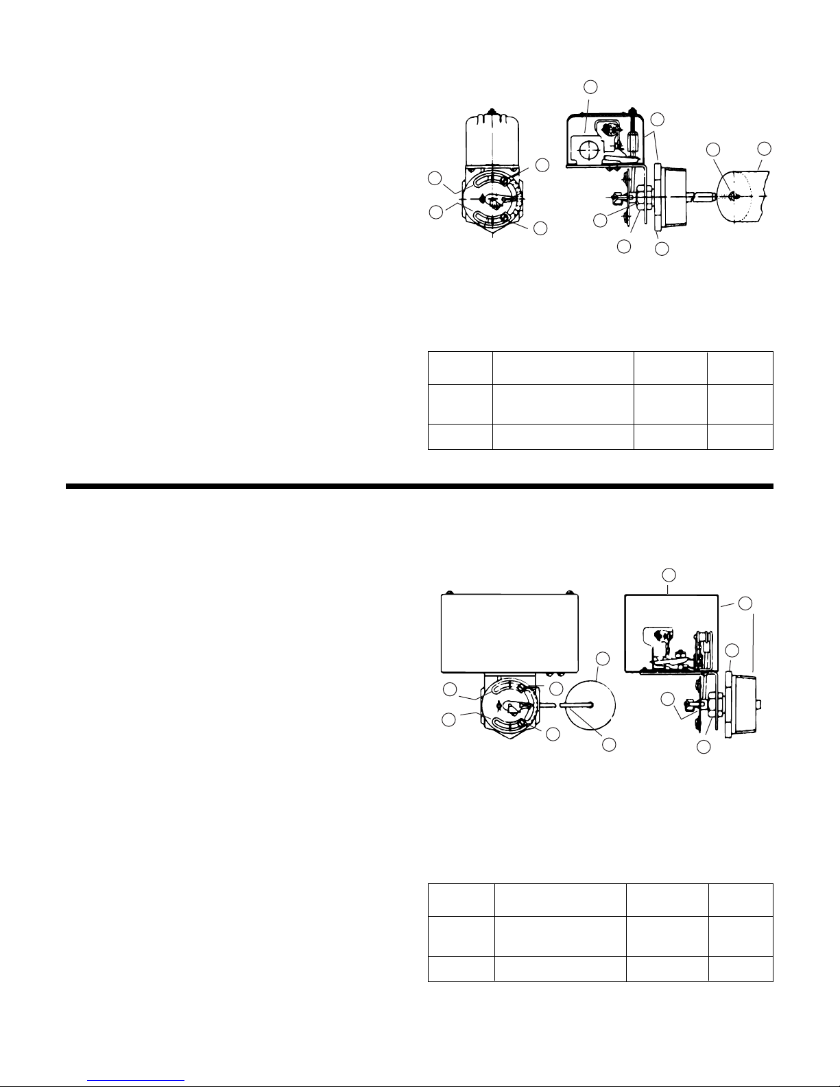
These close coupled vertical centrifugal pumps are equipped
with mechanical seals. If system has not been properly cleaned
prior to installation of pump, foreign matter such as dirt, pipe
scale, core sand, etc. may clog the impeller and damage the
seal. A strainer is recommended in return line to pump. Pump
must not be operated dry. Seals may be damaged if operated
without water present.
1. Close inlet line gate valve and operate pump momentarily
to remove as much liquid as possible from pump. Close
discharge line gate valve.
2. Shut-off and lock out power.
3. Disconnect wiring to motor.
4. Make sure unit is cool enough that pump can be handled
safely. Open receiver drain to remove remaining liquid.
5. Loosen the motor to pump volute fasteners. Assure that
pressure is relieved per caution note.
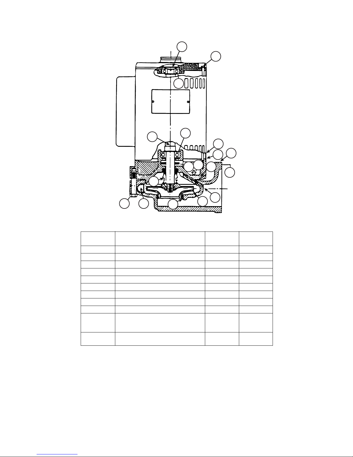
6. Remove three capscrews holding pump head to pump
case and lift motor, pump head and impeller out of pump
case.
7. Hold top end of motor shaft with large screwdriver
or screwdriver socket and back off impeller (counter-
clockwise) with a rectangular bar or other flat tool inserted
between vanes of the impeller.
8. Remove the rotating part of the mechanical seal from the
end of the shaft.
9. Remove the four thru-bolts holding motor end bell and
stator to pump head, and mark end bell, stator, and pump
head for proper orientation later.
10. Remove pump head and rotor assembly from stator being
careful to keep all belleville washers or finger springs
properly oriented in space above top motor bearing. (On A.
O. Smith motor, rotor will stay with stator and washers are
in lower end of bell.)
11. Remove rotor and lower bearing from pump head. Remove
water slinger from slot in pump head.
12. Remove stationary ceramic part of mechanical seal and
cup rubber from recess in pump head.
13. To install new seal proceed as follows: Clean recess in
pump head thoroughly. Coat recess and outer edge of new
cup rubber with grease. Place new ceramic part of seal in
the cup rubber and press firmly into recess by hand,
making certain both parts bottom evenly. If assembly can-
not be bottomed with fingers place cardboard disc on
ceramic and force into place with flat tool.
14. Regrease upper motor bearing with Chevron BRB greases
or equal.
15. Reassemble rotor into pump head and being careful not to
chip or damage ceramic part of seal. Water slinger must
be slipped into recess in head before assembling. A thin
coating of oil or grease on inside edge of hole in slinger will
cause the slinger to slip easily over end of rotor shaft.
16. With the motor vertical, top end bell down, and with
belleville washers or finger springs properly oriented in the
top end bell recess, lower the rotor and head assembly as
a unit, holding it by rotor shaft.
17. Orient the pump head properly and install the thru-bolts.
18. Place motor vertically with pump end up. Do not attempt
assembly of the head and impeller with shaft horizontal.
19. The carbon (rotating) part of the seal should not be loose.
If it is, hold it in place with small amount of grease. Using
a clean, lint-free cloth, wipe the mating surfaces perfectly
clean. Grease rubber lightly and push seal onto shaft so
that the carbon will contact the ceramic seat.
20. Replace the impeller on the shaft (clockwise rotation),
making sure it is tight.
21. Reassemble the unit in reverse order (step 3 thru 1) when
assembling the pump. Use care to insure tight gasket to
prevent water leakage. A new gasket should be ordered
with replacement seal.
22. Close drain and slowly open inlet valves. See warning.
23. Be sure there is adequate water in receiver before operat-
ing pump. Allow short period of operation to clear up occa-
sional slight leakage as seal surfaces adjust themselves.
24. Jog to check motor rotation. See caution.
25. Observe operation thru several cycles.
INSTRUCTIONS FOR THE REPLACEMENT OF MECHANICAL SEALS ON
“WATCHMAN”UNIT WITH “A”DESIGN PUMP & MOTOR ASSEMBLIES
CAUTION: HOT SURFACES
Surfaces are hot when system is in operation. Do not
touch hot receiver, let unit cool before servicing. Failure to
follow these instructions could result in injury or property
damage.
WARNING: HIGH VOLTAGE
Disconnect and lock out power before connecting or
servicing unit. Failure to follow these instructions could
result in serious injury or death.
CAUTION: PRESSURIZED SYSTEM
Operating system may contain very hot water under
pressure. Close inlet and open drains before servicing.
When servicing, loosen screws and move components to
assure pressure is relieved before removing screws. Keep
drains open during servicing. Failure to follow these instruc-
tions could result in injury or property damage.
CAUTION: DO NOT RUN DRY.
SEAL DAMAGE MAY OCCUR.
Inspect pump seal regularly for leaks. Replace as required.
Failure to follow these instructions could result in injury or
property damage.
WARNING: EXPLOSIBLE
Do not pressurize receiver. Isolate receiver during leak
test. Do not plug overflow. Do not restrict vent opening to
atmosphere. Open valves slowly. Failure to follow these
instructions could result in serious injury or death.
CAUTION: DO NOT REVERSE
Reverse operation can cause extensive damage to
pumps. Jog the motor to test for direction of rotation. Failure
to follow these instructions could result in injury or property
damage.