Bell and Gossett ecocirc XL User manual

Installation, Operation, and
Maintenance manual
ecocirc XL


Table of Contents
1 Introduction and Safety............................................................................................................................................................. 3
1.1 Introduction.................................................................................................................................................................................. 3
1.2 Safety terminology and symbols................................................................................................................................................3
1.3 Environmental safety................................................................................................................................................................... 3
1.4 Product warranty..........................................................................................................................................................................3
1.5 Spare parts....................................................................................................................................................................................4
2 Transportation and Storage.......................................................................................................................................................4
2.1 Inspect the delivery..................................................................................................................................................................... 4
2.2 Transportation guidelines...........................................................................................................................................................4
2.3 Storage guidelines.......................................................................................................................................................................4
2.3.1 Storage location...................................................................................................................................................................4
3 Product Description...................................................................................................................................................................4
3.1 Pump design................................................................................................................................................................................ 4
3.2 Product nomenclature.................................................................................................................................................................4
3.3 Technical data.............................................................................................................................................................................. 5
3.4 Scope of delivery......................................................................................................................................................................... 5
3.5 Accessories...................................................................................................................................................................................5
4 Installation................................................................................................................................................................................. 5
4.1 Pump handling.............................................................................................................................................................................5
4.2 Tools required for pump installation.........................................................................................................................................5
4.3 Facility requirements...................................................................................................................................................................5
4.3.1 Pump location...................................................................................................................................................................... 5
4.3.2 Minimum inlet pressure at the suction port..................................................................................................................... 6
4.3.3 De-rating table..................................................................................................................................................................... 6
4.3.4 Piping requirements............................................................................................................................................................6
4.4 Electrical requirements............................................................................................................................................................... 6
4.5 Pump installation......................................................................................................................................................................... 6
4.6 Change the position of the motor housing.............................................................................................................................. 7
4.7 Electrical installation....................................................................................................................................................................7
4.7.1 Power supply connection................................................................................................................................................... 7
4.7.2 I/O connections....................................................................................................................................................................8
4.7.3 Connection assignment......................................................................................................................................................8
5 System Description................................................................................................................................................................... 8
5.1 User interface............................................................................................................................................................................... 8
5.1.1 User interface locking/unlocking.......................................................................................................................................8
5.2 Functions.......................................................................................................................................................................................8
5.2.1 Control mode.......................................................................................................................................................................8
5.2.2 Night set back mode...........................................................................................................................................................9
5.2.3 ∆p-T control .........................................................................................................................................................................9
5.2.4 T-Constant temperature control........................................................................................................................................ 9
5.2.5 ∆p-∆T control ...................................................................................................................................................................... 9
5.2.6 ∆T constant ..........................................................................................................................................................................9
5.2.7 External start/stop................................................................................................................................................................9
5.2.8 Analog Input.........................................................................................................................................................................9
5.2.9 Signal relay........................................................................................................................................................................... 9
5.2.10 External sensors (optional)............................................................................................................................................... 9
5.2.11 Communication bus .......................................................................................................................................................10
5.2.12 Automatic two-pump operation ...................................................................................................................................10
6 System Setup and Operation.................................................................................................................................................. 10
6.1 Configure the pump settings...................................................................................................................................................10
6.1.1 Change the communication parameters........................................................................................................................10
6.1.2 Change the control mode................................................................................................................................................ 10
6.1.3 Change the set point.........................................................................................................................................................10
6.1.4 Change the displayed unit of measurement..................................................................................................................10
6.2 Start or stop the pump..............................................................................................................................................................11
6.2.1 Automatic air venting procedure.................................................................................................................................... 11
6.2.2 Activate automatic two-pump operation .......................................................................................................................11
7 Maintenance............................................................................................................................................................................11
8 Troubleshooting.......................................................................................................................................................................11
8.1 Periodic inspection....................................................................................................................................................................11
8.2 Display messages...................................................................................................................................................................... 11
8.3 Fault and error codes................................................................................................................................................................12
Table of Contents
ecocirc XL Installation, Operation, and Maintenance manual 1

8.4 Alarm codes............................................................................................................................................................................... 12
8.5 Faults, causes, and remedies................................................................................................................................................... 12
9 Other Relevant Documentation or Manuals............................................................................................................................ 13
9.1 Embedded Software and Driver Software License Agreement.......................................................................................... 13
Table of Contents
2 ecocirc XL Installation, Operation, and Maintenance manual

1 Introduction and Safety
1.1 Introduction
Purpose of this manual
The purpose of this manual is to provide necessary information for:
• Installation
• Operation
• Maintenance
CAUTION:
Read this manual carefully before installing and using the
product. Improper use of the product can cause personal in-
jury and damage to property, and may void the warranty.
NOTICE:
Save this manual for future reference, and keep it readily available at
the location of the unit.
1.2 Safety terminology and symbols
Hazard levels
Hazard level Indication
DANGER:
A hazardous situation which, if not
avoided, will result in death or se-
rious injury
WARNING:
A hazardous situation which, if not
avoided, could result in death or
serious injury
CAUTION:
A hazardous situation which, if not
avoided, could result in minor or
moderate injury
NOTICE:
• A potential situation which, if
not avoided, could result in
undesirable conditions
• A practice not related to per-
sonal injury
Hazard categories
Hazard categories can either fall under hazard levels or let specific sym-
bols replace the ordinary hazard level symbols.
Electrical hazards are indicated by the following specific symbol:
Electrical Hazard:
Hot surface hazard
Hot surface hazards are indicated by a specific symbol that replaces the
typical hazard level symbols:
CAUTION:
Qualified personnel
WARNING:
This product is intended to be operated by qualified person-
nel only.
1.3 Environmental safety
The work area
Always keep the station clean.
Waste and emissions regulations
Observe these safety regulations regarding waste and emissions:
• Appropriately dispose of all waste.
• Handle and dispose of the processed liquid in compliance with
applicable environmental regulations.
• Clean up all spills in accordance with safety and environmental
procedures.
• Report all environmental emissions to the appropriate authorities.
CAUTION: Radiation Hazard
Do NOT send the product to Xylem if it has been exposed to
nuclear radiation, unless Xylem has been informed and ap-
propriate actions have been agreed upon.
Electrical installation
For electrical installation recycling requirements, consult your local
electric utility.
Recycling guidelines
Always follow local laws and regulations regarding recycling.
FCC Statement — USA only (Federal Communications Commission)
This device complies with Part 15 of the FCC Rules. Operation is sub-
ject to the following two conditions:
1. this device may not cause harmful interference and
2. this device must accept any interference received, including inter-
ference that may cause undesirable operation.
This equipment has been tested and found to comply with the limits for
a Class B digital device, pursuant to Part 15 of the FCC Rules. These
limits are designed to provide reasonable protection against harmful
interference in a residential installation. This equipment generates,
uses and can radiate radio frequency energy and, if not installed and
used in accordance with the instructions, may cause harmful interfer-
ence to radio communications. However, there is no guarantee that in-
terference will not occur in a particular installation. If this equipment
does cause harmful interference to radio or television reception, which
can be determined by turning the equipment off and on, the user is en-
couraged to try to correct the interference by one or more of the fol-
lowing measures:
• Reorient or relocate the receiving antenna.
• Increase the separation between the equipment and receiver.
• Consult the dealer or an experienced radio/TV technician for help.
Changes or modifications not expressly approved by the manufacturer
responsible for compliance could void the user’s authority to operate
the equipment.
1.4 Product warranty
Coverage
Xylem undertakes to remedy defects in products from Xylem under
these conditions:
• The faults are due to defects in design, materials, or workmanship.
• The faults are reported to a local sales and service representative
within the warranty period.
• The product is used only under the conditions that are described
in this manual.
• The monitoring equipment that is incorporated in the product is
correctly connected and in use.
• All service and repair work that is done by Xylem authorized per-
sonnel.
• Genuine Xylem parts are used.
• Only Ex-approved spare parts and accessories that are authorized
by an Ex-approved Xylem representative are used in Ex-approved
products.
Limitations
The warranty does not cover defects that are caused by these situa-
tions:
•Deficient maintenance
• Improper installation
•Modifications or changes to the product and installation that are
made without consulting a Xylem authorized representative
• Incorrectly executed repair work
• Normal wear and tear
Xylem assumes no liability for these situations:
1 Introduction and Safety
ecocirc XL Installation, Operation, and Maintenance manual 3
• Bodily injuries
• Material damages
• Economic losses
Warranty claim
Xylem products are high-quality products with expected reliable oper-
ation and long life. However, should the need for a warranty claim
arise, contact your local sales and service representative.
1.5 Spare parts
WARNING:
Only use original spare parts to replace any worn or faulty
components. The use of imitation spare parts may cause mal-
functions, damage, and injuries as well as void the warranty
and the UL listing.
2 Transportation and Storage
2.1 Inspect the delivery
1. Inspect the package for damage or missing items upon delivery.
2. If applicable, unfasten the product by removing any screws, bolts,
or straps. For your personal safety, be careful when you handle
nails and straps.
3. Remove packing material from the product.
4. Dispose of all packing material in accordance with local regula-
tions.
5. Inspect the product to determine if any parts have been damaged
or are missing.
Contact your local sales representative if there are any issues.
2.2 Transportation guidelines
Precautions
WARNING:
• Observe accident prevention regulations in force.
• Crush hazard. The unit and the components can be
heavy. Use proper lifting methods and wear steel-toed
shoes at all times.
Check the gross weight that is indicated on the package in order to se-
lect proper lifting equipment.
Position and fastening
The unit should be transported in an upright position as indicated on
the package. Make sure that the unit is securely fastened during trans-
portation and cannot roll or fall over. The product can be safely trans-
ported at ambient temperature from -40°F to +158°F (-40°C to +70°C)
with humidity <95% (non-condensing) and protected against dirt, heat
source, and mechanical damage.
2.3 Storage guidelines
2.3.1 Storage location
NOTICE:
• Protect the product against humidity, dirt, heat sources, and me-
chanical damage.
• The product must be stored at an ambient temperature from
-13°F to +131°F (-25°C to +55°C) and humidity < 95% (non-con-
densing).
3 Product Description
3.1 Pump design
• The ecocirc XL is a large wet rotor pump with energy efficient,
electronically commutated permanent magnet motor.
• The pump is designed for systems with variable flow rates to opti-
mize pump operation thus reducing energy consumption. The
pump can be set to any one of the multiple operating modes
available, with each designed for a specific application to achieve
high performance and maximum energy savings.
• A single pump can handle heating, cooling, and plumbing appli-
cations with a choice for cast iron or bronze lead-free body pumps
to handle HVAC and potable water applications. The pumps are
also suitable for a 50/50 percent water/glycol circulating fluid. The
built-in electrical overload and dry run protection provide safety
and protection to pump from damage.
Intended use
WARNING:
California Proposition 65 warning! This product contains
chemicals known to the state of California to cause cancer
and birth defects or other reproductive harm.
The pump is suitable for:
• Potable hot water (only with bronze pump body models)
• Hot water heating systems
• Cooling and cold water systems
The pump can also be used for:
• Solar systems
• Geothermal applications
Improper use
DANGER:
Do not use this pump to handle flammable and/or explosive
liquids.
WARNING:
Unintended use of the pump may create dangerous condi-
tions and cause personal injury and damage to property.
WARNING:
Do NOT install this pump in swimming pools or marine areas.
Failure to follow these instructions could result in serious per-
sonal injury, death and/or property damage.
THIS IS A NON-SUBMERSIBLE PUMP
WARNING:
Do NOT exceed the maximum working pressure of the
pump. This information is listed on the nameplate of the
pump.
NOTICE:
Do not use this pump to handle liquids containing abrasive, solid, or
fibrous substances, toxic or corrosive liquids, potable liquids other than
water, or liquids not compatible with the pump construction material.
Water pH must be maintained between 7-9 and water hardness must
not exceed 14 grains/ gallon.
An improper use of the product leads to the loss of the warranty.
3.2 Product nomenclature
Example: ecocirc XL B 15–75
ecocirc XL high efficiency pump series
B Pump type:
Blank = Cast iron
B = bronze pump body for pota-
ble hot water pumping
2 Transportation and Storage
4 ecocirc XL Installation, Operation, and Maintenance manual
Example: ecocirc XL B 15–75
-15 Maximum pump head (FT)
-75 Maximum pump flow rate (GPM)
3.3 Technical data
Feature Description
Motor model Electronically commutated motor with perma-
nent magnet rotor
Series ecocirc XL
Rated voltage 1 x 115 V ±10%
1 x 208–230 V ±10%
Frequency 50/60 Hz
Power consumption 100–1700 W
IP protection IP 44
Insulation class Class 155 (F)
Maximum working
pressure The maximum pressure is indicated on pump
nameplate
175 PSI (12 bars)
Liquid temperature
range 14°F (-10°C) to 230°F (110°C)
Ambient temperature
range 32°F (0°C) to 104°F (40°C)
Ambient humidity 95% non-condensing
Pumping media Water and water/glycol mixtures1up to 50%.
Sound pressure ≤ 43 dB (A)
EMC (electromagnetic
compatibility) EN 55014-1:2006 + A1:2009 + A2:2011, EN
55014-2:1997 + A1:2001 + A2:2008, EN
61000-3-2:2006 + A1:2009 + A2:2009, EN
61000-3-3:2008, 61800-3:2004+A1:2012.
Leakage current < 3.5 mA
I/O auxiliary +15 VDC
power supply Imax < 40 mA
Fault signal relay Vmax < 250 VAC
Imax < 2 A
CSA certification NSF/ANSI-372 compliant (bronze body parts)
3.4 Scope of delivery
Inside the package you will find:
• Pump unit
• Insulating shells for pump body — for heating applications
• O-ring to be used as replacement between motor housing and
pump body
• Two (2) gaskets for flanged connection
• 20 mm x ½” NPT electrical fitting
• IOM and Quick Start guide
3.5 Accessories
• Companion flanges
• Fastener Packs consisting of 4 bolts and 4 nuts (for 2–bolt models)
• Fastener Packs consisting of 8 bolts and 8 nuts (for 4–bolt models)
• Pressure sensor (for details see section 5.2.10 of this manual)
• Temperature sensor (for details see section 5.2.10 of this manual)
• Wireless module
• RS–485 module
4 Installation
Precautions
WARNING:
• Observe accident prevention regulations in force.
• Use suitable equipment and protection.
• Always refer to the local and/or national regulations,
legislation, and codes in force regarding the selection of
the installation site, plumbing, and power connections.
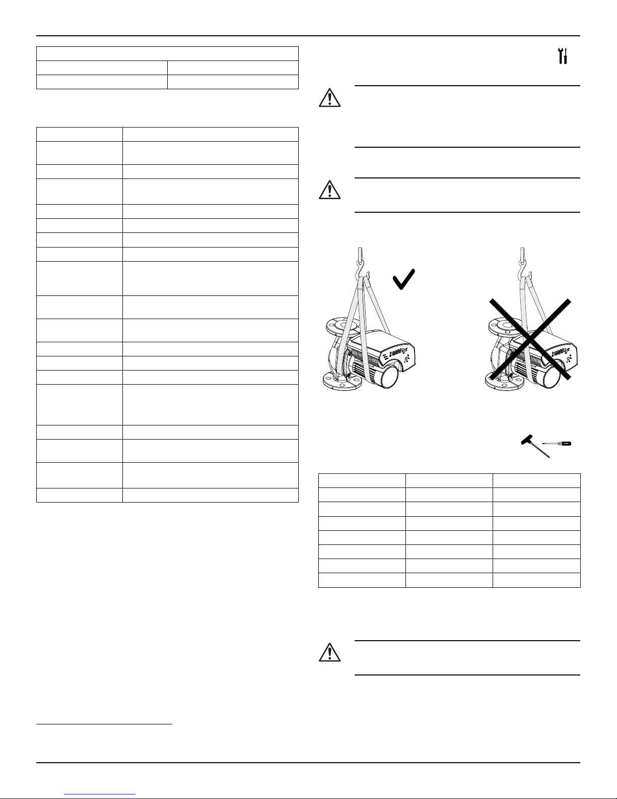
4.1 Pump handling
WARNING:
Observe local codes and regulations setting the limits for
manual lifting or handling.
Always lift the pump by the motor housing or pump body. If the pump
weight exceeds the manual handling limits, use lifting equipment with
lifting straps.
4.2 Tools required for pump installation
• T-Handle with allen screw
• Control screw driver – with 2 mm blade size
Model number Allen screw size (mm) T-handle length (in)
20–35 5 8
36–45 5 8
15–75 5 8
55–45 6 10
20–140 6 10
65–130 8 12
40–200 8 12
4.3 Facility requirements
4.3.1 Pump location
DANGER:
Do not use this unit in environments that may contain flam-
mable/explosive or chemically aggressive gases or powders.
Guidelines
Observe the following guidelines regarding the location of the prod-
uct:
1The pump can be used with water/propylene glycol mixtures up to 50% with a maximum viscosity of 50cST at 14°F (-10°C). The pump has built-in overload and
thermal protection to protect the pump from overload due to increased fluid viscosity. Pump performance is based on 77°F (25°C). Therefore pumping of glycol
mixtures will affect max performance, depending on mixture concentration and temperature.
4 Installation
ecocirc XL Installation, Operation, and Maintenance manual 5
• Make sure that the installation area is protected from any fluid
leaks, or flooding.
• If possible, place the pump slightly higher than the floor level.
• Provide shut-off valves on the suction and discharge sides of the
pump.
• The relative humidity of the ambient air must be less than 95%
non-condensing.
• This pump is suitable for indoor use only.
CAUTION:
CAUTION: PROPERTY DAMAGE HAZARD. It is not advisable
to install circulators in an attic or upper floor over finished liv-
ing space. If the circulator must be installed over head, or
over expensive equipment, provide adequate drainage in
the event of leakage. Failure to follow these instructions
could result in property damage.
4.3.2 Minimum inlet pressure at the suction port
The values in the table below are the inlet pressures above the atmos-
pheric pressure.
Nominal Suction
Diameter Fluid tempera-
ture 77°F (25°C) Fluid tempera-
ture 203°F
(95°C)
Fluid tempera-
ture 230°F
(110°C)
1½” 4.5 PSI 16 PSI 25 PSI
2” 4.5 PSI 16 PSI 25 PSI
3” 7.5 PSI 19 PSI 28 PSI
NOTICE:
• Ensure that the suction pressure is never below the values speci-
fied above, as this could cause cavitation and damage the pump.
• The inlet pressure plus the pump pressure against a closed valve
must be lower than maximum admissible system pressure.
4.3.3 De-rating table
The following table indicates percent decrease in input power draw,
with the increase in temperature of circulating water and the ambient.
Ambient
temperature
Fluid Temperature (°C)
-10 60 95 110
32°F–77°F
(0°C–25°C) 100% 100% 100% 100%
86°F (30°C) 100% 100% 80% 70%
104°F (40°C) 100% 100% 70% 55%
4.3.4 Piping requirements
Precautions
CAUTION:
• Use pipes suited to the maximum working pressure of
the pump. Failure to do so can cause the system to rup-
ture, with the risk of injury.
• Make sure that all connections are performed by quali-
fied installation technicians and in compliance with the
regulations in force.
• Do not use a shut-off valve on the discharge side in the
closed position for more than a few seconds. If the
pump must operate with the discharge side closed for
more than a few seconds, a bypass circuit must be instal-
led to prevent overheating of the water inside the
pump.
Piping checklist
• Pipes and valves must be correctly sized.
• Pipe work must not transmit any load or torque to pump flanges.
• Be sure to minimize any pipe-strain on the pump:
• Support suction and discharge piping by the use of pipe
hangers near the pump.
• Line up the vertical and horizontal piping so that the bolt-
holes in the pump flanges match the bolt-holes in the pipe
flanges.
• Do not attempt to spring the suction or discharge lines in po-
sition. This may result in unwanted stress in the pump body,
flange connections and piping.
• The code for pressure piping (ANSI B31.1) lists many types of
supports available for various applications.
4.4 Electrical requirements
• The NEC and local codes must be followed at all times. If a branch
circuit is fitted with ground fault circuit breaker, ensure that the cir-
cuit breaker is suitable for use with inverter-driven appliances.
Electrical connection checklist
Check that the following requirements are met:
• The electrical wires are protected from high temperature and vi-
brations.
• The current type and power supply voltage connection must cor-
respond to the specifications on the name plate on the pump.
• Use wires at least 14 AWG to supply power to the pump. Follow
all local and NEC wiring codes and practices.
The electrical control panel checklist
NOTICE:
The electrical supply must match the electrical rating of the pump. Im-
proper combination could fail to guarantee protection of the unit.
Check that the following requirements are met:
• The control panel circuit breaker be sized properly to protect the
pump against short-circuit.
• The pump has built in overload and thermal protection, no addi-
tional overload protection is required.
The motor checklist
Electrical supply and grounding wires must be suitable for at least
194°F (90°C).
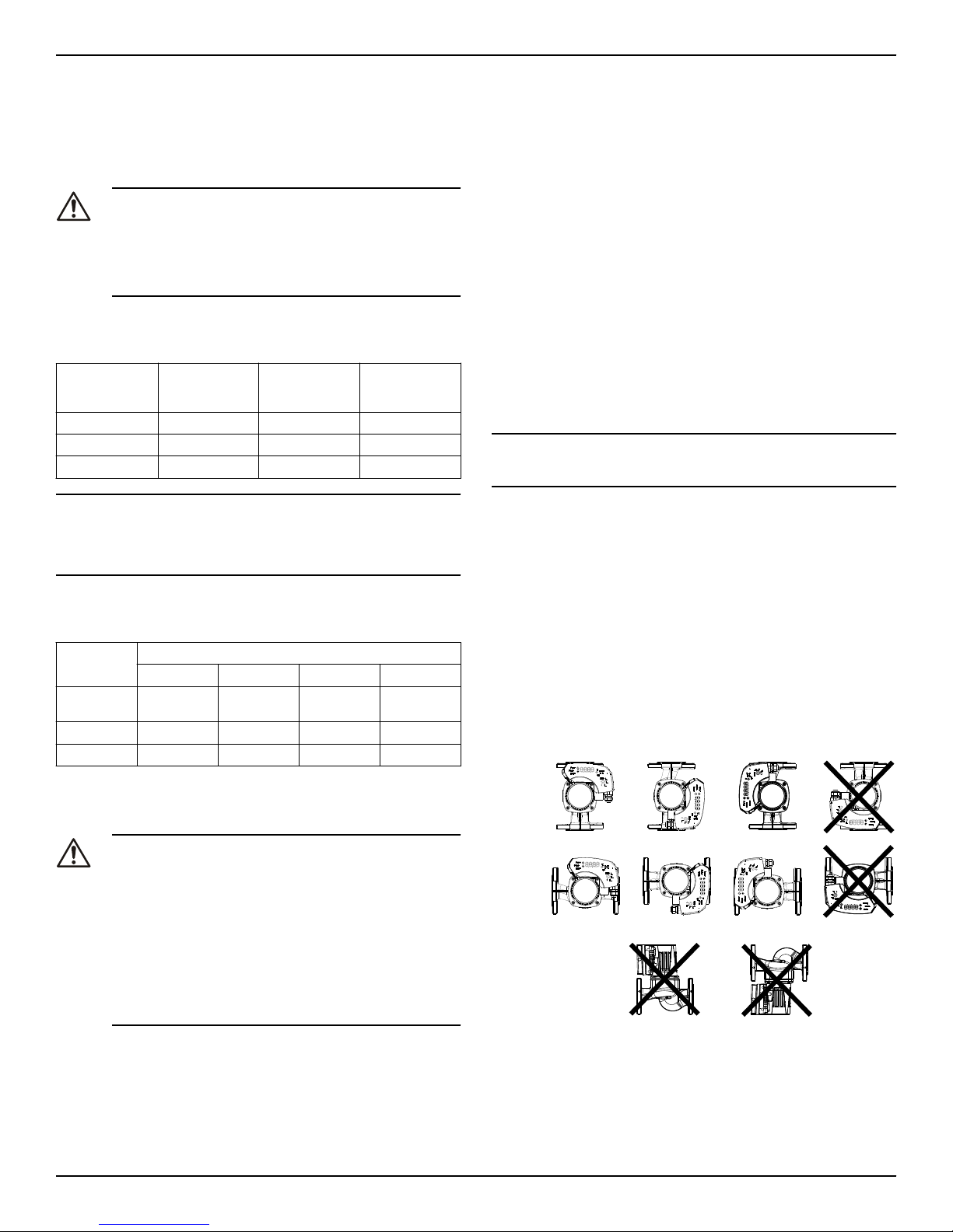
4.5 Pump installation
1. Install the pump according to the liquid flow direction.
• The arrow on the pump housing shows the flow direction
through the pump body.
• The pump must be installed with the motor in a horizontal
position. For more information about allowed positions, refer
to the following image:
Figure 1: Allowed pump installation
2. If necessary, rotate the position of the motor for better visibility of
the user interface.
Section 4.6 below describes the procedure of changing of motor
orientation.
3. If applicable, install the thermal insulation shells.
4 Installation
6 ecocirc XL Installation, Operation, and Maintenance manual
• Only use the pump thermal shells that are included in the de-
livery. Do not insulate the motor housing, the electronics can
overheat and cause the pump to thermally overload.
• The thermal shells that are included with the pump must only
be used in hot water circulation applications with fluid tem-
perature above 68°F (20°C). The thermal shells are permea-
ble to water vapor.
• If the customer installs the vapor barrier insulation shells for
cold water application, then the pump housing must not be
insulated above the motor flange. The drain opening must
be kept unobstructed in order that the accumulated conden-
sation can run out.
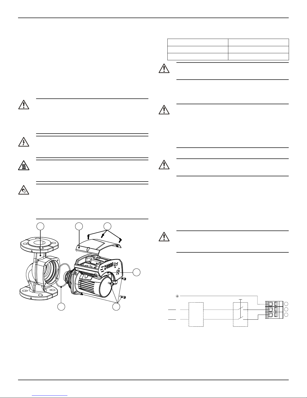
4.6 Change the position of the motor
housing
WARNING:
• Drain the system if possible or close the service valves
on both sides of the pump before disassembling the
pump. The pumped fluid can be pressurized and may
be scalding hot.
• There is the risk of escaping vapor when the motor is
separated from the pump housing.
Electrical Hazard:
Before starting work on the unit, make sure that the unit and
the control panel are isolated from the power supply and
cannot be energized.
CAUTION:
Burn hazard. During operation various surfaces on the unit
will become hot. To avoid burn injury, use heat protective
gloves.
WARNING:
• A strong magnetic field is created when the rotor is re-
moved from or inserted into the motor housing. This
magnetic field can be harmful to pacemaker wearers
and others with medical implants. In addition, the mag-
netic field may attract metal parts to the rotor which can
cause injuries and/or damage the bearing of the pump.
32
465
1
Figure 2: Change the position of the pump head
1. Loosen the four hex-head screws (2) that fix the motor to the
pump housing (4) using the T-handle allen wrench described.
2. Rotate the motor (1) in 90° steps to the desired position.
3. In case of separation of the motor housing from the pump body
(4):
a) avoid removing the rotating assembly from motor housing;
b) pay attention to the magnetic hazard listed before.
A defective O-ring must be replaced. An O-ring is already availa-
ble inside the package as spare part.
4. Properly align and tighten the four hex-head screws (2) that affix
the motor to the pump body (4) according to the torque table giv-
en below in a criss cross pattern.
M6 90 in-lb
M8 170 in-lb
M10 340 in-lb
CAUTION:
Check for the presence of leaks after reassembling the
pump.
4.7 Electrical installation
Precautions
WARNING:
• Make sure that all connections are performed by a quali-
fied electrician in accordance with all applicable codes,
ordinances and good practices. Failure to follow these
instructions could result in serious injury, death and/or
property damage.
• Before starting work on the unit, make sure that the unit
and the control panel are isolated from the power sup-
ply and cannot be energized.
Grounding (earthing)
WARNING:
Reduced risk of electric shock during operation of this pump
requires the provision of acceptable grounding.
Be sure the following are adhered to. Failure to follow these instruc-
tions could result in serious personal injury, death, and/or property
damage.
• If means of connection to the supply connection box (wiring com-
partment) is other than grounded metal conduit, ground the
pump back to service using a copper conductor at least the size of
the circuit conductors supplying the pump.
• Connect the ground wire to the green grounding terminal in the
wiring compartment.
4.7.1 Power supply connection
WARNING:
Do not make any connection in the pump control box unless
the power supply has been switched off for at least 2 mi-
nutes.
For models with standard terminal block connection:
1. Open the terminal box cover removing the screws (5).
2. Thread the ½” NPT electrical fitting into the conduit connection of
the pump.
3. Connect the cable according to the wiring diagram.
a. Connect the ground wire, if used.
b. Connect the wires.
4. Close the terminal box cover.
1
2
3
L
N
115V
L1
L2
208-230V CB
Figure 3: Wiring diagram
4 Installation
ecocirc XL Installation, Operation, and Maintenance manual 7
Start / Stop
20
1918
17
1615
14
1312
11
10987654321
CNL NO 15V S+S- P+ P- T+ T- AB GND AB GND
Figure 4: Connection diagram
For cable terminations, see above connection diagram.
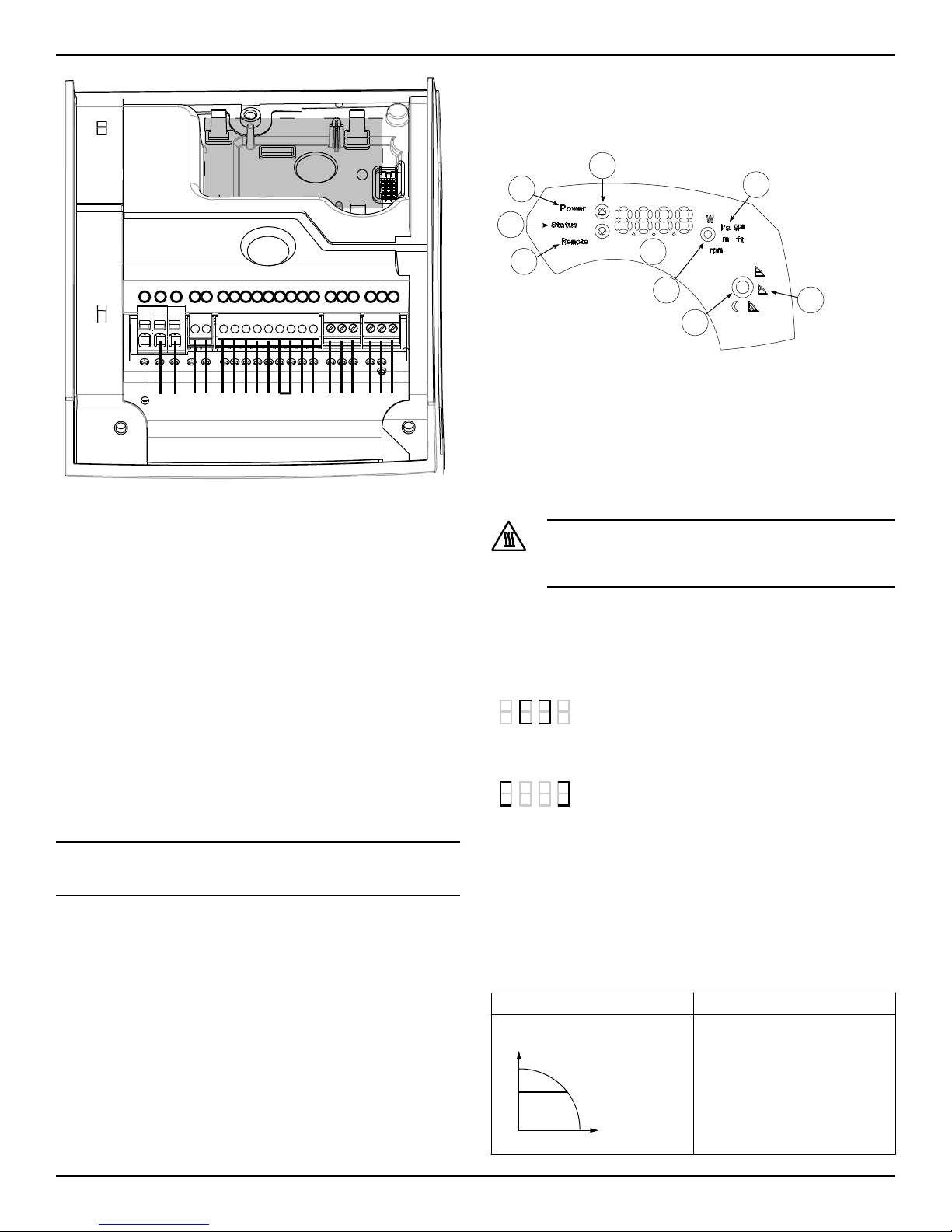
4.7.2 I/O connections
1. Open the terminal box cover removing the screws (5). Refer to fig-
ure 2 on page 7. Use control screwdriver described under section
4.2 to access terminal blocks.
2. Connect the appropriate wires according to the terminal block di-
agram and the requirements of section Connection assignment
(page 8) given below in section 4.7.3.
3. Close the terminal box cover.
• For a two-pump connection, wire them through a communication
cable connecting the 2 RS-485 ports at the pumps to terminals 15,
16 & 17.
4.7.3 Connection assignment
• For all electrical connections use heat resistant wires or cable rat-
ed for at least 194°F (90°C). The cables should not touch the mo-
tor housing, the pump or the piping.
• Power and control wires must be run in separate channels.
• Metal conduit for power wiring must only be attached to 1/2” NPT
conduit fitting.
NOTICE:
Cable glands are only available for low voltage wiring to protect
against cable slippage and vapor ingress into the terminal box.
5 System Description
5.1 User interface
9
8
7
6
5
4
2
1
3
Figure 5: User interface diagram
1. Control mode button
2. Control mode indicators
3. Parameter button
4. Parameter indicators
5. Setting buttons
6. Numeric display
7. Power indicator
8. Status / Fault indicator
9. Remote control indicator
Hot Surface:
Burn hazard. During the normal operation, the pump surfa-
ces may be so hot that only the buttons should be touched to
avoid burns.
5.1.1 User interface locking/unlocking
The user interface will automatically lock if no button is pressed for ten
minutes, or if the upper setting button (5) and the parameter button (3)
are pressed for two seconds. See User interface (page 8).
If a button is pressed when the user interface is locked, the display (6)
shows:
To unlock the user interface, press the upper setting button (5) and the
parameter button (3) for two seconds. The display (6) will show:
Now it is possible to change the pump setting as preferred.
5.2 Functions
The main functions of the pump and control modes are selectable
through the pump user interface and the embedded I/O. Advanced
functions or communication features, can only be set via bus protocol
or the optional Wireless module. See the advanced functions manual at
www.bellgossett.com.
5.2.1 Control mode
Mode Description
Constant pressure
Hset
The pump maintains a constant
pressure at any flow demand. The
desired head of the pump can be
set via user interface. See section
6.1.2 Change set point.
5 System Description
8 ecocirc XL Installation, Operation, and Maintenance manual
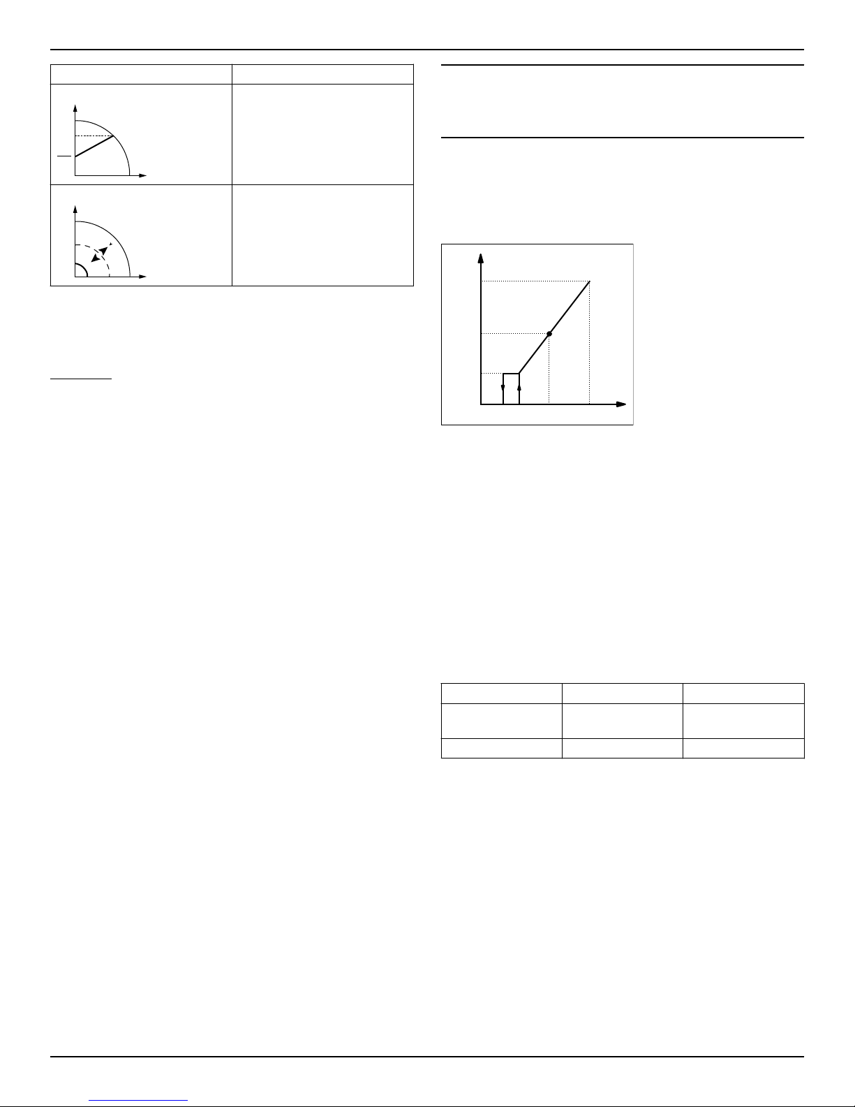
Mode Description
Proportional pressure
2
Hset
Hset
The pump pressure is continuous-
ly increased/decreased depend-
ing on the increased/decreased
flow demand. The maximum head
of the pump can be set via user in-
terface. See section 6.1.2 Change
set point.
Fixed speed control
Max
min
Speed
setpoint
The pump maintains a fixed speed
at any flow demand. The speed of
the pump can be set via user inter-
face. See section 6.1.2 Change set
point.
All the above control modes can be combined with the night mode
function.
5.2.2 Night set back mode
The night set back mode cannot be used in cooling systems.
Prerequisite
• The pump is installed between boiler outlet and system supply.
• The night set back feature is initiated when the pump recognizes a
water temperature change brought about by the boiler or high
level control system.
The night set back mode is active only in combination with:
• Proportional pressure
• Constant pressure
• Constant speed
This function reduces power consumption of the pump to the minimum
when heating system is not running. An algorithm detects the water
temperature change and automatically adjusts the speed of the pump.
The pump returns to the original set point as soon as the system re-
starts.
5.2.3 ∆p-T control
This function adjusts the nominal differential pressure set point accord-
ing to the temperature of the pumped media.
For details refer to advanced functions manual on www.bellgos-
sett.com
5.2.4 T-Constant temperature control
This functional mode changes the speed of the pump in order to main-
tain a constant temperature of the pumped media. It is suitable for
heating systems with fixed system characteristics, for example Domes-
tic Hot Water Systems.
For details, refer to the advanced functions manual on www.bellgos-
sett.com
5.2.5 ∆p-∆T control
This function requires the external temperature probe type KTY83 (see
section 5.2.10 of this manual).
This function adjusts the nominal differential pressure set point de-
pending on the differential temperature of the pumped media. An ex-
ternal temperature sensor Type: KTY83 is required for this functionality
(see section 5.2.10 of this manual for details).
For details, refer to the advanced functions manual on www.bellgos-
sett.com
5.2.6 ∆T constant
This function alters the speed of the pump in order to maintain a con-
stant differential temperature of the pumped media.
For details, refer to the advanced functions manual on www.bellgos-
sett.com
5.2.7 External start/stop
The pump can be started or stopped via an external dry contact or a
relay that is connected to terminals 11 and 12. The pump unit is provid-
ed by default, with the terminals 11 and 12 jumpered. See Figure 4 on
page 8.
NOTICE:
• The pump provides 5 VDC through the start / stop terminals.
• No external voltage must be provided to start / stop terminals.
• The cables connected to terminals 11 and 12 shall not exceed 65
feet in length.
5.2.8 Analog Input
The pump integrates a 0-10 V analog input at terminals 7 and 8. See
terminal diagram figures for changing the setpoint. See Figure 4 on
page 8.
When a voltage input is detected, the pump switches to fixed speed
control mode automatically and starts to run according to the following
diagram:
Vin[V]
Speed
[rpm]
Vset 101.51.2
min
Max
Setpoint
Figure 6: Voltage input detected
Pump stops at 1.2 V
Pump restarts at 1.5 V
5.2.9 Signal relay
A dry contact relay is provided at terminals 4 and 5. See connection di-
agram, figure 4 on page 8, for location. If there is a fault, the relay con-
tact closes to display a red status light and the error code on the user
interface display. See User interface (page 8). The relay contact closure
can also be used to energize a remote fault display.
Ratings
• Voltage: 115/208 – 230/1
• Imax < 2 A
5.2.10 External sensors (optional)
The pump can be equipped with a differential pressure sensor and a
temperature sensor according to the following table:
Sensor description Type Terminals
Differential pressure
sensor 4-20mA 15 PSI
30 PSI
9 - 10
Temperature sensor KTY83/121 13 - 14
Pressure sensor setup
1. Install pressure sensor on the pipe
2. Connect wires at terminals 9 and 10. See Figure 4 on page 8.
3. Power the pump on.
4. Upon startup, the pump detects the sensor and displays the setup
menu.
5. Select the right sensor model and confirm the selection using the
parameter button (3). See User interface (page 8).
6. The pump will run through the startup sequence and automatical-
ly start working in constant pressure mode.
7. The setpoint can be changed using the settings button (5). See
User interface (page 8).
External temperature sensor setup
The external temperature sensor setup and related control modes are
available only through RS-485 or wireless module connection.
For details refer to advanced functions manual on www.bellgos-
sett.com
5 System Description
ecocirc XL Installation, Operation, and Maintenance manual 9

Wireless module
The wireless module is an optional module, to be coupled with the
ecocircXL circulators. When correctly configured, it generates a wire-
less network accessible by a mobile device, tablet or a personal com-
puter. See wireless module instructions manual for details.
5.2.11 Communication bus
The pump has a built-in RS-485 communication channel (terminals
15-16-17). See Figure 4 on page 8.
The pump can communicate with external BMS systems via Modbus or
BACnet protocol. For a complete description of the protocols, refer to
the advanced functions manual at www.bellgossett.com.
NOTICE:
When remote control is active, the set points and control modes are
managed only through communication channels and cannot be
changed via the user interface. The displayed quantity and unit of
measurement remain active on the user interface.
5.2.12 Automatic two-pump operation
Backup operation
Only the lead pump runs. The second pump starts in case of failure of
the lead pump.
Alternate operation
Only one pump runs at the time. The working time is switched every 24
hours so that workload is balanced between both pumps. The second
pump is started immediately in case of failure of the lead pump.
Parallel operation
Both pumps run simultaneously at the same set point. The lead pump
determines the behavior of the full system and is able to optimize the
performance. To guarantee the required performance with the mini-
mum power consumption, the lead pump starts or stops the lag (sec-
ond) pump to satisfy system requirement of flow and head.
6 System Setup and Operation
Precaution
CAUTION:
Always wear protective gloves when handling the pumps and
motor. When pumping hot liquids, the pump and its parts
may exceed 40°C (104°F).
NOTICE:
The pump must not run dry as this can result in the destruction of the
bearings. Fill the system correctly with liquid and vent the air before
first start-up.
NOTICE:
• Never operate the pump with discharge valve closed for longer
than a few seconds.
• Do not expose an idle pump to freezing conditions. Drain all liq-
uid that is inside the pump. Failure to do so can cause liquid to
freeze and damage the pump.
• The suction plus shut-off discharge pressure must not exceed the
pump pressure rating.
• Do not use the pump if cavitation occurs. Cavitation can damage
the internal components.
6.1 Configure the pump settings
Change the pump settings using one of the following methods:
• User interface
• Bus communication
• Wireless communication
6.1.1 Change the communication parameters
Change pump communication parameters. See User interface (page 8).
1. Switch off the pump.
Wait until the power indicator light turns off.
2. Switch on the pump.
3. When the display shows COMM (COM), press the parameter but-
ton (3) to access the communication menu.
4. Select one of the below parameters using the settings button (5).
•BAUD (BDR) = baud rate setup (available values 4.8 - 9.6 -
14.4 - 19.2 - 38.4 - 56.0 - 57.6 kbps)
•ADDR (ADD) = address setup (available address 1-255 for
Modbus 0÷127 for BACnet)
•MODU (MDL) = optional module setup (0 = no module; 1 =
Wireless module; 2 = RS-485 module)
5. Press the parameter button to enter the submenu
6. Edit the values using setting buttons.
7. Press the parameter button to confirm and store the new values.
8. Press mode button to exit the submenu.
9. Repeat above procedure for each of the three parameters.
If no buttons are pressed for 10 seconds, then the pump exits the cur-
rent menu and continues start-up procedure. All the parameters that
are changed but not confirmed restore back to previous state.
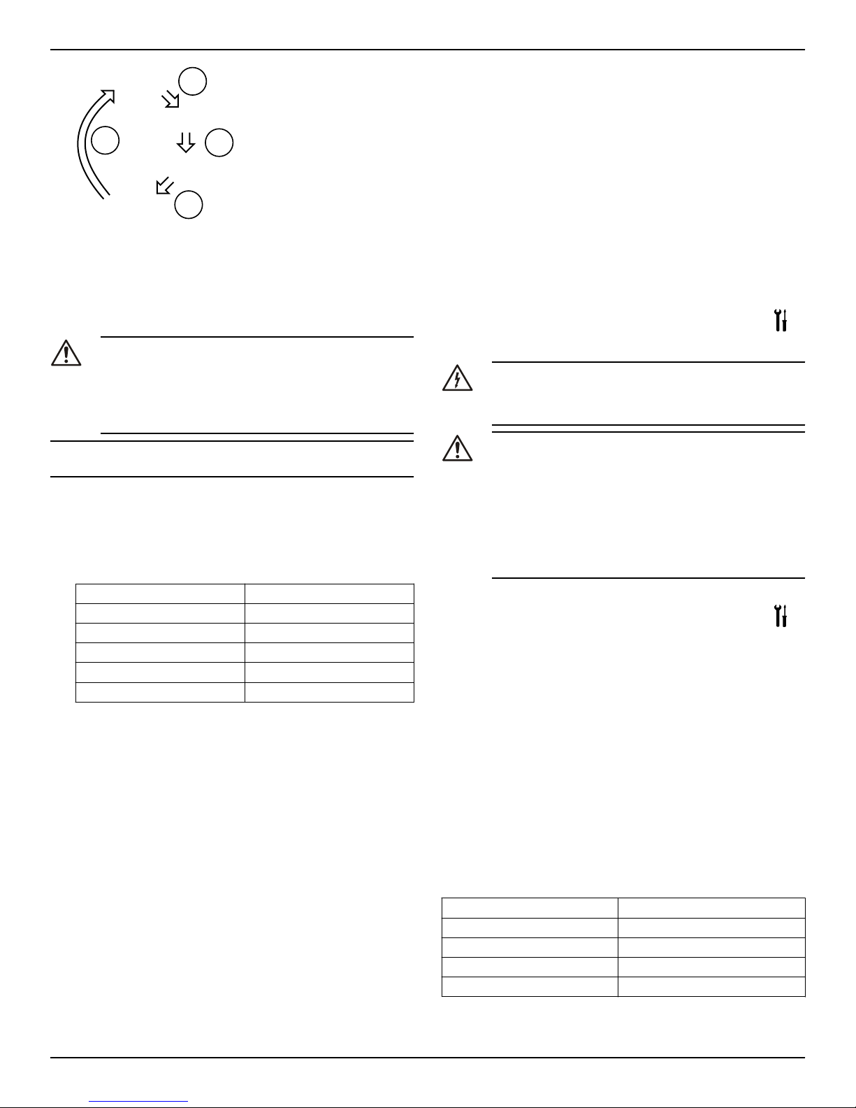
6.1.2 Change the control mode
The pump can be controlled by a BMS (Building management system)
or other devices through the RS-485 communication port via Modbus
or BACnet protocol.
The following instructions are used when making the change on the
user interface. See User interface (page 8).
• Press the operating mode button (1).
• The operating modes are cyclically changed by the pressed but-
ton.
mode
mode
mode mode
mode
mode
6.1.3 Change the set point
See User interface (page 8).
1. Press one of the arrow setting buttons (5).
The display starts to blink.
2. Change the value using the buttons (5).
3. Wait 3 seconds to store and activate the new set point.
The display will stop blinking to confirm the change.
NOTICE:
If a check valve is installed on the system, ensure that the pump head is
sufficient to allow flow through the system.
6.1.4 Change the displayed unit of measurement
Power, Flow, Head and Speed parameters cyclically change by press-
ing the parameter button (3). In order to change the unit of measure-
ment, follow these steps:
1. Press the button (3) to change the unit of measurement. See User
interface (page 8).
6 System Setup and Operation
10 ecocirc XL Installation, Operation, and Maintenance manual
Power
Speed
Head
Flow
Parameter
button
Parameter
button
Parameter
button
Parameter
button
2. When flow and head are displayed, by pressing the button (3) for
more than one second at each of these parameters, the unit of
measurement automatically changes as below:
• Flow: m3/h ↔ gpm (US)
• Head: m ↔ ft
6.2 Start or stop the pump
CAUTION:
• The pump must not run dry as this can result in prema-
ture failure of the bearings in a very short time. Fill and
vent the system correctly before first start-up. The pump
rotor chamber will be vented after the pump is powered
on with an automatic air venting procedure. "deg" will
be displayed indicating degassing process.
NOTICE:
The system cannot be vented through the pump.
• Start the pump in one of the following ways:
• Switch on power to supply the pump.
• Close the start/stop contact by jumpering terminals 11 and
12 or through a remote dry contact..
• Send start command through the communication bus.
The pump starts pumping in constant pressure mode with the fol-
lowing default set points:
7.5 ft 15–XX (Max head 15 ft)
10 ft 20–XX (Max head 20 ft)
18 ft 36–XX (Max head 36 ft)
20 ft 40–XX (Max head 40 ft)
27.5 ft 55–XX (Max head 55 ft)
32.5 ft 65–XX (Max head 65 ft)
For more information about how to change setting, see Configure
the pump settings (page 10).
• Stop the pump in one of the following ways:
• Switch off power supply to the pump.
• Open the start/stop contact.
• Send stop command through the communication bus.
6.2.1 Automatic air venting procedure
At each power-on of the pump unit, an automatic air venting proce-
dure is executed. During this phase, the user interface displays "deg"
(degassing) and a count-down begins until the completion of the pro-
cedure.
The procedure can be recalled or skipped:
• Manually by pressing simultaneously the two buttons (5). See User
interface (page 8). The feature will remain disabled until power to
pump is disconnected.
The procedure can be permanently enabled or disabled by:
• Manually by pressing simultaneously the two buttons (5) for at
least 10 seconds. See User interface (page 8). Or
• Via communication bus. See the advanced functions manual on
www.bellgossett.com.
6.2.2 Activate automatic two-pump operation
Once the communication cable is connected, configure only the “lead”
pump. The twin pump submenu for this configuration is available at
each power-on, when the drive is displaying SING (which stands for
“Single Pump).
The following procedure must be executed during the start-up phase
of the pump.
1. Enter the two-pump sub menu when the display is showing
TWMA (two-pump master) or TWSL (two-pump slave).
2. Select the applicable two-pump operation.
•bcup = backup operation
•alte = alternative operation
•para = parallel operation
3. Push the parameter button to activate the new setting.
The second pump is configured by the lead pump.
7 Maintenance
Precaution
Electrical Hazard:
Disconnect and lock out electrical power before installing or
servicing the unit.
Wait 2 minutes before opening the conduit box.
WARNING:
• Always wear protective gloves when handling the
pumps and motor. When pumping hot liquids, the
pump and its parts may exceed 40°C (104°F).
• Maintenance and service must be performed by skilled
and qualified personnel only.
• Observe accident prevention regulations in force.
• Use suitable equipment and apply personal protection.
• Risk of property damage, serious personal injury or
death. You must repair or replace the pump if corrosion
or leakage is found.
8 Troubleshooting
Introduction
See User interface (page 8).
• In case of any alarm that allows the pump to continue running, the
display shows a blinking alarm code and the last quantity select-
ed, while the status indicator (8) becomes orange.
• In case of a failure that stops the pump, the display shows the er-
ror code permanently and the status indicator (8) becomes red
8.1 Periodic inspection
Bell & Gossett ecocircXL circulators are designed to provide years of
trouble-free service. It is recommended that periodic inspections be
made to check for potential problems with the pump. If any leakage or
evidence of leakage is present, repair or replace the unit.
8.2 Display messages
Table 1: Default
Operating LEDs / Display Cause
Power On Pump powered
All LEDs and display On Start-up of the pump
Status Green light Pump is working properly
Remote On Remote communication is activated
7 Maintenance
ecocirc XL Installation, Operation, and Maintenance manual 11

Table 2: Fault messages
Operating LEDs / Dis-
play Cause Solution
Power Off Pump is not connected
or is incorrectly con-
nected
Check connection
Power failure Check power supply
and circuit breaker
Status light Orange Alarm for system prob-
lem Check the displayed
alarm code and find
cause from table 8.3.
Status light Red Pump failure Check the displayed
error code and find the
cause from table 8.2.
Remote Off Remote communica-
tion is deactivated If the communication
does not work, check
the connection and the
configuration parame-
ters for communication
on the external con-
troller.
8.3 Fault and error codes
Error code Cause Solution
E01 Internal communication lost Restart the pump2
E02 High motor current Restart the pump2
E03 DC Bus overvoltage Indicates excessive
power through the
pump. Confirm system
setup, verify correct
position and opera-
tion of check valves.
E04 Motor stall Restart the pump2
E05 Data memory corrupted Restart the pump2
E06 Voltage supply out of operating
range Check the electrical
system voltage and
wiring connection.
E07 Motor thermal protection trip Check the presence of
foreign material
around impeller and
rotor that cause over-
load. Check installa-
tion conditions and
temperature of the
water and ambient air.
Wait until the motor is
cooled. If the error
persists try to restart
the pump2.
E08 Inverter thermal protection trip Check installation con-
ditions and ambient
air temperature.
E09 Hardware error Restart the pump.
E10 Dry run Check for system leak-
age or fill the system.
8.4 Alarm codes
Alarm code Cause Solution
A01 Fluid sensor malfunction Switch off the pump for 5
minutes and then power
on.
If the problem persists,
contact local B&G repre-
sentative.
A02 High temperature of the
fluid Check water temperature
value
A03 Automatic speed reduction
to prevent inverter over-
heating
Check installation condi-
tions and rectify status of
the system
A05 Data memory corrupted Switch off the pump for 5
minutes and then power
on. If the problem persists,
contact local B&G repre-
sentative.
A06 External temperature
probe malfunction Check the probe and the
connection to the pump
A07 External pressure sensor
malfunction Check the sensor and the
connection to the pump
A12 2–pump communication
lost If both pumps show the
A12 alarm, check the con-
nection between the
pumps. If one of the pump
is switched off or shows an-
other error code, check the
section 8.1 and 8.2 to find
the problem
A20 Internal alarm Switch off the pump for 5
minutes and then power
on. If the problem persists,
contact local B&G repre-
sentative.
8.5 Faults, causes, and remedies
The pump does not start
Cause Remedy
No power. Check the power supply and ensure that
it is properly terminated to the pump
power.
Tripped circuit breaker or
ground-fault protection de-
vice or the circuit breaker.
Reset power supply circuit breaker and
determine cause for overload.
The pump starts but the thermal protection is triggered after a short
time
Cause Remedy
Incorrect wiring size or circuit break-
er rating not suitable for motor cur-
rent.
Check and replace the compo-
nents as necessary.
Thermal overload protection due to
excessive input. Check the pump working con-
ditions.
Missing a phase in the power supply. Verify continuity and ensure
proper wiring connections.
2Switch off the pump for 5 minutes and then power on. If the problem persists, contact service.
8 Troubleshooting
12 ecocirc XL Installation, Operation, and Maintenance manual

The pump is noisy
Cause Remedy
Not thoroughly vented. Switch off the pump and after 30 seconds
switch on again to restart the automatic
air-venting procedure.
Cavitation due to insuffi-
cient suction pressure. Increase the system suction pressure
within the admissible range.
Foreign objects in pump. Clean the system.
Worn out bearing Contact local B&G representative.
9 Other Relevant Documentation or
Manuals
9.1 Embedded Software and Driver Software
License Agreement
With the purchase of the product, the terms and conditions of the li-
cense for the software embedded on the product are considered ac-
cepted. For more information see license condition on www.bellgos-
sett.com
9 Other Relevant Documentation or Manuals
ecocirc XL Installation, Operation, and Maintenance manual 13

Xylem |’zīləm|
1) The tissue in plants that brings water upward from the roots
2) A leading global water technology company
We're 12,500 people unified in a common purpose: creating innovative solutions to meet our world's
water needs. Developing new technologies that will improve the way water is used, conserved, and
re-used in the future is central to our work. We move, treat, analyze, and return water to the
environment, and we help people use water efficiently, in their homes, buildings, factories and farms.
In more than 150 countries, we have strong, long-standing relationships with customers who know us
for our powerful combination of leading product brands and applications expertise, backed by a
legacy of innovation.
For more information on how Xylem can help you, go to xyleminc.com
Xylem Inc.
8200 N. Austin Avenue
Morton Grove, Illinois 60053
USA
Tel: (847) 966-3700
Fax: (847) 965-8379
www.bellgossett.com
Visit our Web site for the latest version of this document
and more information
The original instruction is in English. All non-English
instructions are translations of the original instruction.
©2013 Xylem Inc
Bell & Gossett is a trademark of Xylem Inc or one of its
subsidiaries.
P2002548_Rev. B
Table of contents
Popular Power Pump manuals by other brands

Kärcher
Kärcher SBP 2200 manual

WELCH-ILMVAC
WELCH-ILMVAC DUOSEAL 1402B-01 owner's manual

BLACKMER
BLACKMER XL2B Installation, operation and maintenance instructions

Pentair
Pentair MYERS ME40MC-11-CI owner's manual

Varian
Varian 969-9047 series instruction manual

BLACKMER
BLACKMER XU2A Installation, operation and maintenance instructions


