Benassi RT 80 Manual

S.p.A.
USE AND MAINTENANCE HANDBOOK
MOTORISED HOE
RT 80
06/07/01
S.p.A. RT 80
2
CONTENTS
1) Introduction
2) After-sales service and Warranty
3) Technical details
4) Packing and transport
5) Accessories
6) Safety rules and limits on use
7) Starting and stopping
8) Operating and regulating the machine
9) Mill assembling
10) Maintenance and lubrication
11) End-of season servicing
12) Possible problems and solutions
13) Instructions for a good operation of the
machine
1 -INTRODUCTION
We are pleased that you chose a machine built byBENASSI SPA.
This booklet provides the information and data needed to preserve and use the machine properly.
Themoreyougettoknowyour farming machine,thebetter youwill work. Thereforewestronglysuggestthatbeforestarting work, you carefullyread and
understand this "USER AND MAINTENANCE" booklet.
Youwill findimportantinformationonusing themachinewhichwill allowyoutogetthemostofits technical capacities. You will alsofindprecious
information on howto care for it and service it, in terms of safety, and a guide on running and servicing it in the best possible wayduring the lifetime of your
machine.
For reasons of technical progress, BENASSI SPA reserves the right to modify the mechanical parts, the finishes and the accessories. The data
regarding measures, weights and performance are specified within DIN tolerance. The figures, the descriptions and the technical data are not binding.
2 - AFTER-SALES SERVICE AND WARRANTY
BENASSI SPA provides its customers with an after-sales service for solving anyprobleminvolving the use and the maintenance of its machinery. All the
machines are guaranteed for defective material for 12 months (one year) from purchase. For anyneed, refer to your dealer.
N.B. IMPORTANT WARNING FOR YOUR SAFETY
Always use original BENASSI SPA products, spare parts and accessories; anymodification or application using non-original parts exempts BENASSI
SPAfrom anyresponsibility
BENASSI SPA disclaims all responsibilityin case of application of accessories made byother firms to its machines: Anywarrantywill begivenfor said
applications even when such modifications have been tested byboards of control or certified bypublic bodies as tests on single machines are not valid.
BENASSI SPAW ISHES YOU A PLEASANT W ORK W ITH OUR MACHINES
N.B. PAY SPECIAL ATTENTION TO THE INSTRUCTIONS MARKED OUT BY THE
FOLLOWING SIGN
THIS SYMBOL INDICATES DANGER: FAILURE TO COMPLY WITH THESE
INSTRUCTIONS MAYCAUSE INSIDIOUS OR EVEN FATAL INJURY.
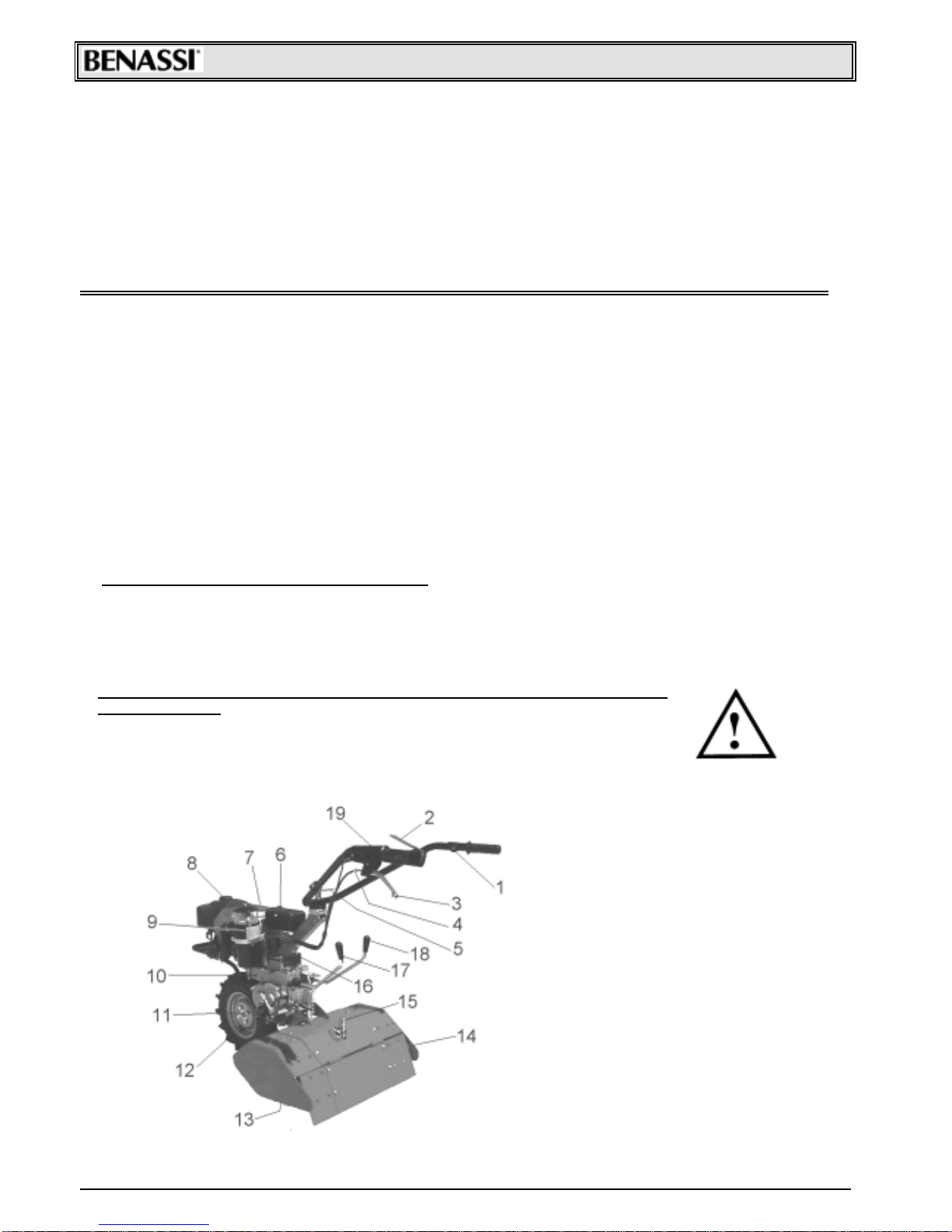
3 – TECHNICAL DETAILS LIST OF MACHINE PARTS
1. Accelerator
2. Stop engine
3. Clutch lever
4. Clutch adjuster
5. Handle-bar adjuster
6. Tool-case
7. Start engine
8. Fuel inserting
9. Air filter
10. Oil level
11. Power take-off
12. Driving wheel
13. Mill
14. Mills bonnet
15. Bonnet adjustment
16. Oil inlet
17. Mills lever
18. Gearbox lever
19. Blocking push button
SpA RT 80
3
ENGINE MINSEL COMPACT 7 HP
CYCLE 8
STROKE 2
FUEL TYPE Gasoline-oil mixture 4%
DISPLACEMENT 148 cc.
NET W EIGHT Kg. 100 complete with accessories
RPM 4500
MAX. POW ER OF THE DRIVING SHAFT 6 HP (Kw. 4,4) whit a consumption of 2,0 Kg/H
CLUTCH Oil bath cone clutch
GEARBOX Oil bath gearbox, four forward speeds and 1 reverse speed.
HANDLE-BAR Height and side adjustment
W HEELS 3.50.8 rubber or metal wheels
MOVING SPEED with:
•tyres 3.50.8
•the engine at 5.000 RPM
GEAR FORW ARD SPEED : Km/h REVERSE SPEED : Km/h
1° 1.5 2.6
2° 3.2
3° 4.5
4° 9.4
The engine fitted on this cultivator has following features:
• Exhaust guard
• Recoil starter
• Oil bath air filter
• Safety device for both forward and backward gear stopping the tiller.
• Standard handlebar with vertical and side adjustment. MACHINE IDENTIFICATION
The machine can be identified through its gearbox unit model and serial
number. The motor serial number is printed on the motor plate or on the motor
carburetor manifold by the manufacturer.
The machine identification data are reproduced on a plate located on the handle-
bar support (right-hand side looking from the operating position), and the serial
number is reproduced both on the motor flange and on the unit (see picture
sideways)
Copy the plate data and the complete serial number on this manual in order to
have them at hand when necessary.
4 - PACKING AND TRANSPORT
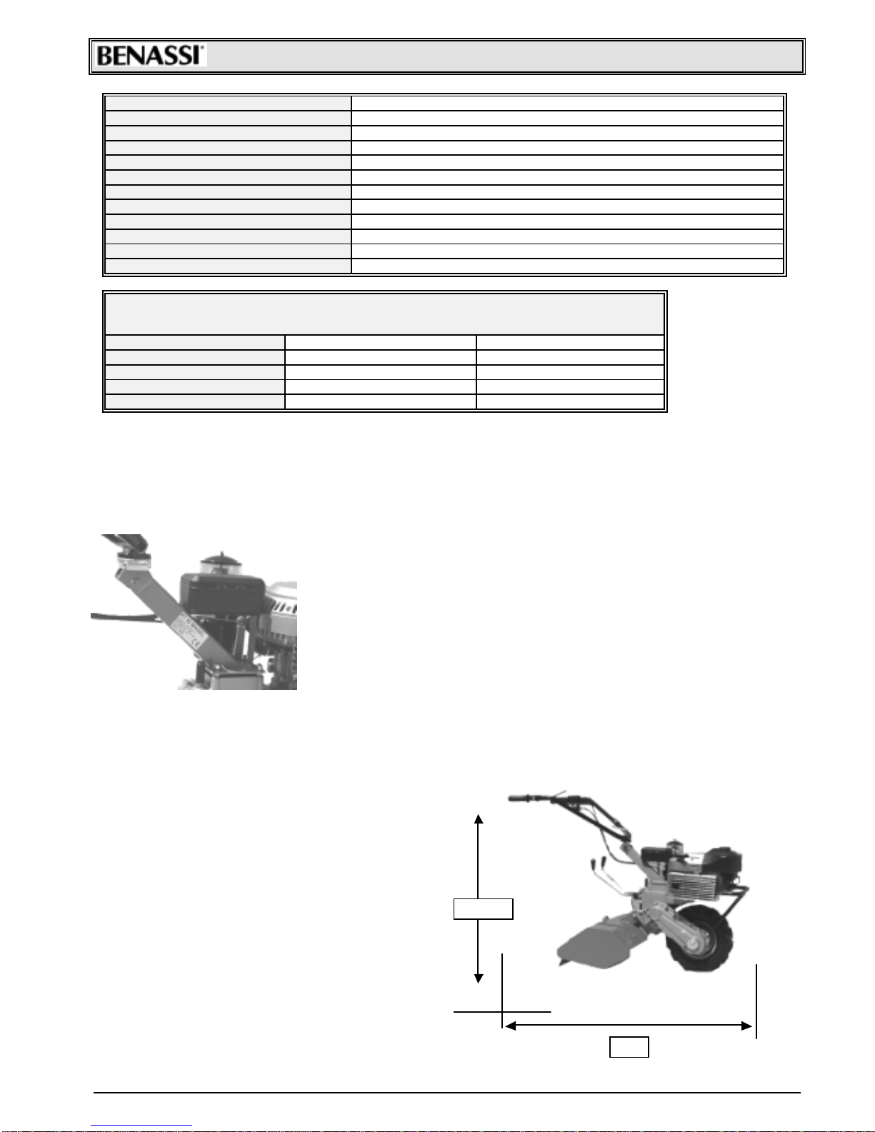
The machine is generally supplied without its accessories, in carton boxes having the following overall dimensions:
• WIDTH : cm. 95
• HEIGHT: cm. 42
• LENGTH : cm. 85
• NET WEIGHT : Kg. 75 (without rotary tiller)
During start-up the total exclusion of kinematic motions
through blocking push button on clutch is scheduled
Accessories are generally supplied separately from the
machine, with or without packing
Free the machine from its packing in order to prepare it to
operate in the following way:
a) Open the packing and free the machine from it, with the
help of another person lift the machine: one taking it from
the wheels, the other from the handle-bars;
b) Adjust handle-bars as desired;
c) Apply the accessories
1410
98+-15

SpA RT 80
4
5 -ACCESSORIES
Spacer with pin for 2^ wheel
application
Cod. 94904400
Front ballast Kg. 21,5
Cod. 98000402
Second rubber wheel 3.50.8
Cod. 97004400
Wheel ballast Kg. 9,5
Cod. 98060100
1^iron wheel
Cod. 97004300
Adjustable furrow-opener with
connection
Cod. 91002511
2^iron wheel
Cod. 97004500
(it is necessary to apply a
spacer cod.94904400)
6 - SAFETY RULES AND LIMITS ON USE
IMPORTANT:
Before using the machine read carefully this operation and
maintenance manual; It will allow you to get from your machine the
best performance of use and duration.
• The use of the machine is forbidden to persons younger than 16 years.
• The operator is responsible of any possible damage and he should always drive the machine carefully and safely.
• Before carrying the machine always empty the fuel tank.
• Before leaving the machine be sure that it is fully stopped.
• Never use the machine without heavy shoes and long transfers. Always inspect the area where you want to work
taking off stones, branches, cables and any other thing which can be dangerous.
• Before starting working, make sure that a radius of minimum 5 m. is completely free.
• Clean any possible leakage of fuel.
• Fill up when the engine is off and not hot, always in an open space far from fires or any heating source and refrain
from smoking during this operation.
• Before starting the machine make sure that you can quickly stop the engine and that you are familiar with the control
levers.
• Never allow the engine to run in enclosed spaces where the highly toxic carbon monoxide could not evacuate.
• Never start or use the machine not completely assembled especially concerning the safety devices and the tiller
protection guards which should always be completely assembled with all its extensions.
• Never fix or clean the tiller blades or any other tools when the engine is running.
• Never work in over 50% sloping ground.
• We are not responsible for accidents due to the wrong use of the machine neglecting the above basic instructions.
• The elimination of the lubricants used must be carried out according to the norms existing in the country of use.
7 – STARTING AND STOPPING
Whenever you set about starting a cold engine, make sure :
• That the gasoline cock “A” is always open. The lever must be
placed towards the outlet pipe.
• That the gasoline has reached the carburetor. If so, by pumping
piston “B”, the gasoline will drop down from the hole on the
upper section of carburetor.
• Then, turn the accelerator control lever placed on the handle-bar
of about ¼.
• Check that the gear-lever and the mill-control lever are idle.

SpA RT 80
5
Check that stop lever and clutch lever are blocked through the
blocking push button (Ref. ”F”)
• Seize the starting-handle “C” by one only hand, pull it gently until the ratchet
gear is engaged. Then give a pull. The cord must never be left free quite
suddenly with the engine running, but followed till when it’s completely
winded-up.
8 - OPERATING AND REGULATING THE MACHINE
The refuelling must be always performed before starting the work, with cold and
stopped engine, using a funnel, and in the open air.
If fuel comes out from the tank, move the machine at once before starting the engine
and dry well the parts wet of gasoline.
We recommend to use always a funnel with a net-filter in order to keep back the
possible impurities.
FUEL-TYPE: gasoline-oil mixture 4%
SAFETY LEVER : The motor hoe is provided with a red safety stop lever connected
to the clutch lever (Ref. G)through side blocking push button (Ref. “F”).
The main function of this lever consists in stopping the engine in the moment in which
the hands are removed from the driving-beams.
It’s recommended not to bind the stop-engine lever “E” to the handle-bar hand-grip.
CLUTCH LEVER : To assure a regular clutch working it is a good rule to check from
time to time the play that the clutch-lever must have: (as shown in the picture) the
lever idle-stroke must be from 8 to 10 mm. In the opposite, act on the adjuster (G)
increasing or decreasing the play according to the need.
DRIVING-BEAMS :
Adjustable in height and transversally, with possibility of locking in the wished
position. This operation must be carried out by means of the screw-handle (“A”) placed
on the lowest section of driving-beams.
SPEED AND MILL CONTROL LEVERS :
The shifting of speed-lever (Ref. “I”)must always happen under the following
conditions:
• With engine idling
• With the hand-clutch-lever (Ref. G) pulled towards the hand-grip.
Anyhow, never force the lever in its shifting.
ATTENTION: The mills rotation must never occur, when the machine is in reverse speed, an
inner lever-system disengages the mill or the reverse-speed.
FUEL INLET
FOR
REPLENISHING
SpA RT 80
6
If this should not occur, apply to a skilled workshop by our concessionary agents.
In the picture, turning lever “A” left the rotary tiller is activated, on the contrary turning it right it is stopped.
POWER TAKE-OFF :
The motor hoe is equipped with a lateral power take off, which may be
employed both with stopped and running machine.
The power take off and its own couplings are unified with most of commercial
fittings.
POWER TAKE-OFF OUTLINE:
Splined 16 UNI 221X120 mm. Working
Turning direction: left.
Max. rev. 440 at 5,000 engine/RPM.
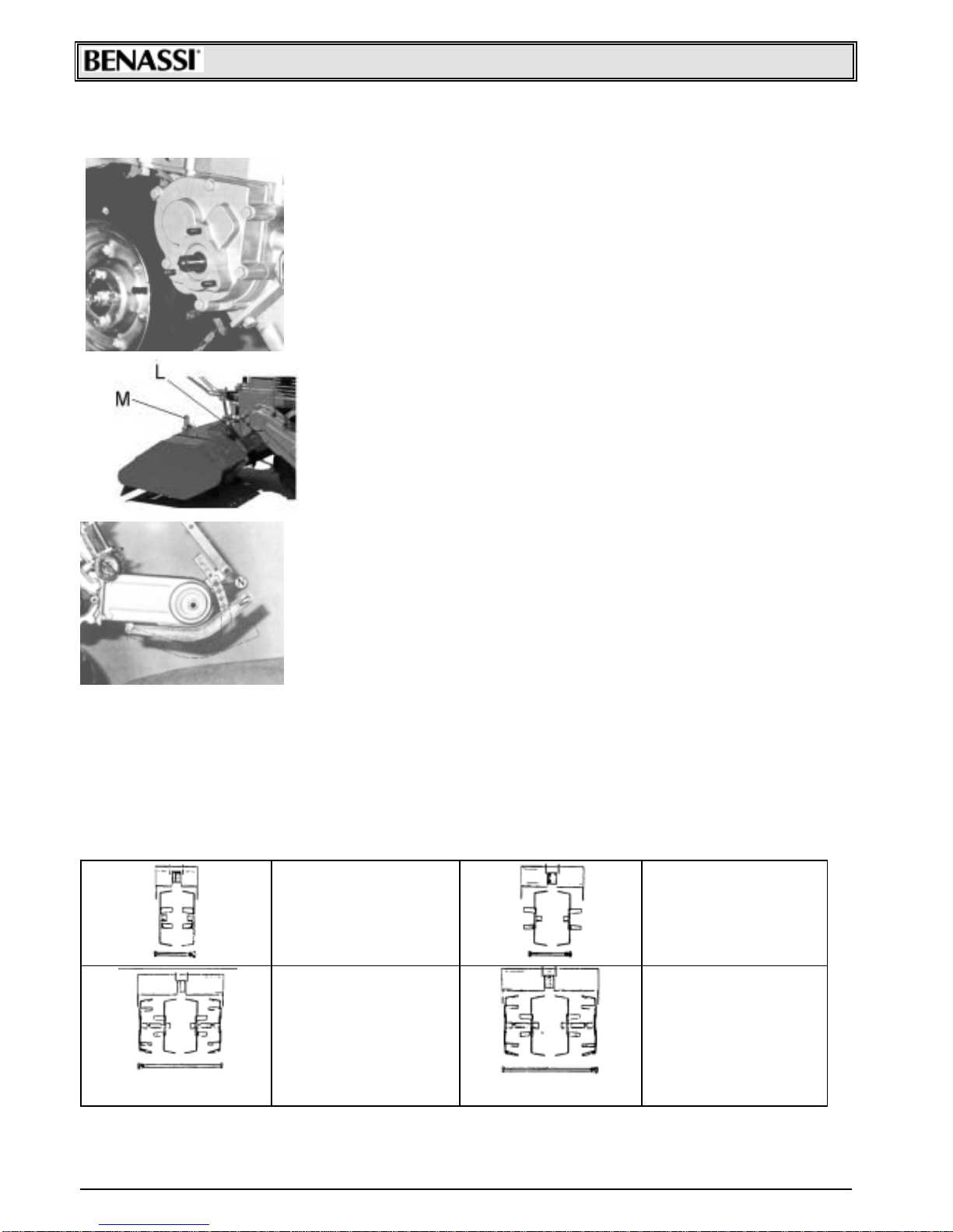
MILL BONNET :
The milling-depth may be adjusted as follows: for working on the surface,
it’s recommended to keep the safety-mill-bonnet lowered.
For a deep working, to sink more in the ground.
For these operations it’s sufficient to act on the pin fixing the bonnet “L” and on
adjusting pin “M”.
DIRECTION - JOINTER :
For getting a more regular machine advancement it is sufficient to operate the
adjustable direction-jointer.
When working on soft ground, it is required to keep the spur up, to help the
machine advancement.
On solid ground it’s right to keep the jointer down, so that sinking in the earth it
prevents a too quick machine advancement.
For this adjustment, act on the pin “N” fixing the jointer.
The machine presented in this manual has been designed to be used only in
agriculture and especially for ground milling.
Any different use is considered contrary to its proper use.
The builder does not assume responsibility for damages or injuries due to improper
use of the machine.
According to the norms, even the respect of the operation, maintenance, and repairing conditions fixed by the Firm
BENASSI SPAis part of a correct use
The machine can be operated, maintained and repaired only by those operators who have read this manual and are
informed of possible dangers.
Any arbitrary modification on the machine exempts the Firm BENASSI SPAfrom any responsibility in case of
damages. 9 – MILL ASSEMBLING
WORKINGWIDTH :18cm.
2 one-side joiners
1 pin cm.17
1 bonnet cm.18
WORKINGWIDTH :26cm.
2 two-side joiners
1 pin cm.17
1 bonnet cm.26
WORKINGWIDTH :32cm.
2 two-side joiners
2 one-side joiners
2 spacers
1 pin cm.31
1 bonnet cm.33
WORKINGWIDTH :38cm.
2 two-side joiners
2 one-side joiners
2 spacers
1 pin cm.36
1 bonnet cm.38

SpA RT 80
7
WORKINGWIDTH :45cm.
4 two-side joiners
2 spacers
1 pin cm.36
1 bonnet cm.45
WORKINGWIDTH :58cm.
4 two-side joiners
2 one-side joiners
4 spacers
1 pin cm.55
1 bonnet cm.58
WORKING WIDTH : 65 cm.
6 two-side joiners
4 spacers
1 pin cm.55
1 bonnet cm.65
10 - MAINTENANCE AND LUBRICATION
PLUG-CONTROL :
From time to time it’s necessary to check the plug wear-level and the
electrodes-distance, which must be of 0.5 mm , as shown in the near drawing.
AIR FILTER CLEANING :
This operation must be performed regularly in the following way:
• clean the filter externally, so to avoid that some earth falls inside during the
disassembling.
• Loose the clips “P”, remove the oil-cup “Q”, take away the filter-element “R”
and wash carefully the different parts with gasoline oil.
• Fill the cup with new oil till reaching the level, as pointed out in the picture.
OIL INLET BLEED :
Every component of the gear-box and transmission is in oil-bath. It’s
necessary to check from time to time the oil-level through screw “S” and fill it up
again, if required, through the vent plug “T”.
USE ONLY OIL FOR TRANSMISSION SAE 30
FRONT-WHEEL OIL LEVEL PLUG :
Check from time to time the oil level on the front wheel through plug “U”, placed
on one side, as shown in the picture. For a perfect machine efficiency, a good
maintenance and a perfect lubrication are necessary.
Check that air filter is clean, in case of oil bath filter check level every 8-10
operating hours or even more frequently when working in dusty grounds. Use motor
oil to restore oil level and clean the cup before filling it.
GEARBOX Check oil level every 50 operating hours removing the cap on the
gearbox sump keeping the machine in horizontal position.
If necessary add SAE 30 oil. It is advisable to replace oil at least every 100
hours.
MILLS Before starting to work check that all screws are tight, check especially
rotary tiller hoe fastening screws.

SpA RT 80
8
11 - END-OF-SEASON MAINTENANCE
OIL DRAG PLUG :
For whatever mechanical repair in the ear-box or in the mill-descent, it’s
necessary to remove the oil.
To make the transmission empty, unscrew the plug “V” placed in the lowest
section of the gear-box.
Before parking the machine:
• wash it accurately with gas oil,
• empty the carburetor tank and clean or replace air filter,
• lubricate and grease all articulated joints and gears,
• replace or repair possible worn parts,
• lubricate cylinder with motor oil through the spark plug hole, pull the start-up
cord so that the piston makes some strokes
• Park the machine in a dry place with wheels on wood tables or even better with wheels up from the floor.
12 - POSSIBLE PROBLEMS AND SOLUTIONS
Possible problems that can be solved by the machine operator:
MOTOR - The motor does not start; check that:
• the gasoline in the tank is more then half.
• the gasoline cock is open
• if the motor is cold , the starter lever is pulled
• the gasoline reaches the carburetor
• the bleed on the tank cap is not clogged
• carburetor jets are not clogged, if necessary, clean
them with air jet
• the spark plug sparks, in order to carry out this check
operation unscrew the spark plug; connect it to the power
supply cable, place the spark plug earthed metal part
(motor cylinder) and make the motor pulley turn as in the
start-up phase. If electrodes do not spark, check the
supply cable junctions, and if this does not solve your
problems, replace the spark plug with one of the same
type. If even this time you should not obtain positive
results, the defect concerns the electric plant (points,
condenser, coil etc.)In this case it is advisable to contact
the nearest service (according to the motor assembled on
the machine).
13 - INSTRUCTIONS FOR A GOOD OPERATIONOF THE MACHINE
• Carry out a good breaking-in of the motor and of the
machine (for at least 10 hours do not exceed 70%of motor
power)
• always use the clutch before using any lever
• do not keep the clutch disengaged for long periods of
time
• never force gear levers, if you cannot engage them,
jerkily release the clutch
• never force the motor.
• do not work at full speed for long periods, in particular
during hot days
• periodically check tyres pressure ( Atm. 1.3)
• when assembling the different tools, do not damage
shaft spigot and spline, check that tool screws and lockpin
are tight, in particular the rotary tiller hoe screws and the
screws fastening the mowing bar
• do not leave the machine in the rain.
IMPORTANT: using the machine for a
long time you should use ear
protection system.

SpA RT 80
9
TESTS FOR CE CERTIFICATION
EC Certificate of conformity conforming to EEC directions 89/392
40010 SanMatteo della Decima BO Italy Via Lampedusa n°1 Tel. (051) 682.46.56
Declare in sole responsibility, that the product CULTIVATOR RT 80 to which this certificate applies, conforms
to the basic safety and health requirements to EEC directions 89/392 and to the other relevant EEC directions : PREN
709/94 - N67 CEN TC 144/WG4 - PREN 836/92 - EN 294.
THE PRESIDENT
S.Matteo della Decima li 20 -12 - 1994
TEST AND RESULT
TYPE: CULTIVATOR MODEL RT 80
Noise level at operator’s ear : LAeq = 87,1 dB (A)
Test condition: 1,6 Mt at the center of the handlebar
Handlebar vibration according to ISO.5349 : 5,7 m/sec2

SpA RT 80
10
S.p.A.
Via Lampedusa,1 - 40010 S. MATTEODELLADECIMA (BO) - ITALY
TEL. 0039/051/82.05.34 TELEFAX 0039/051/682.61.64
Table of contents
Other Benassi Lawn And Garden Equipment manuals


