Benchmark 1261-000 User manual

READ ALL INSTRUCTIONS BEFORE FIRST USE.
KEEP THIS MANUAL FOR FUTURE REFERENCE.
KEEP AWAY FROM CHILDREN.
WEAR CSA APPROVED
EYE PROTECTION
WEAR EAR
PROTECTION
WEAR A
FACE MASK
4006849
M1K-ZK5-100
120V 60Hz 5.9Amp
5 year limited warranty on tool
BISCUIT JOINER

1
PRODUCT SPECIFICATIONS
5.9 AMP BISCUIT JOINER
Voltage 120V~ 60Hz
Rated Power 5.9A
Blade Diameter 4" (100mm)
No-load speed 11600 /min
Arbor 7/8" (22mm)
Blade diameter 4" approx. (100mm)
Fence adjustment range 0-90
Fence height adjustment range 0 - 1-9/16” (0 – 40mm)
Cutting depth: 0 - 3/4” (0 - 19mm)
Weight 5.8 lbs (2.65kg)
NEED ASSISTANCE?
Call us on our toll- free customer support line:
1-866-349-8665 (Monday through Friday 9am – 5pm Eastern Standard Time)
• Technical questions
• Replacement parts
• Parts missing from package

1261-000
BISCUIT JOINER
2
TABLE OF CONTENTS
Product Specifications .................................................................................. 1
Table of Contents .......................................................................................... 2
General Safety Warnings ............................................................................... 3
General Power Tool Safety Warnings............................................................... 5
Work Area Safety ........................................................................................... 5
Electrical Safety............................................................................................. 5
Personal Safety ............................................................................................. 5
Specific Safety Rules for Biscuit Joiners ........................................................ 7
Safety Symbols ............................................................................................. 9
Know Your Biscuit Joiner.............................................................................. 10
Assembly .................................................................................................... 11
Operation .................................................................................................... 13
Maintenance ............................................................................................... 18
Troubleshooting........................................................................................... 20
Exploded View ............................................................................................ 21
Parts List .................................................................................................... 22
Warranty ..................................................................................................... 24

3
GENERAL SAFETY WARNINGS
IMPORTANT SAFETY INSTRUCTIONS
Read and understand all safety and operational instructions. Failure to follow the
safety rules listed below and other basic safety precautions may result in serious
personal injury. Keep this manual, sales receipts and applicable warranty forms
for future reference.
SAFETY SYMBOLS
The purpose of safety symbols is to alert you of the potential safety RISKS.
Recognize and understand them. Follow the instructions provided.
SYMBOL MEANING
Failure to obey a DANGER safety alert WILL result in serious personal
injury or death to you or to others. Always obey all messages following
this symbol to reduce the risk of serious personal injury or death.
Failure to obey a WARNING safety alert MAY result in serious personal
injury or death to you or to others. Always obey all messages following
this symbol to reduce the risk of potential serious personal injury or
death.
Failure to obey a CAUTION safety alert MAY result in personal injury
or property damage to you or to others. Always obey all messages
following this symbol to reduce the risk of personal injury or
property damage.
Failure to obey a NOTICE or a CAUTION (without a safety alert)
MAY result in property damage to you or to others. Always obey all
messages following this symbol to reduce the risk of property damage.
ALWAYS WEAR EYE PROTECTION THAT CONFORMS WITH CSA
Z94.3 or ANSI SAFETY STANDARD Z87.1
FLYING DEBRIS can cause permanent eye damage. Prescription
eyeglasses ARE NOT a replacement for proper eye protection. The
usage of a safety standard compliant face shield placed over proper
safety glasses or goggles can reduce the risk of facial injury.
Non-compliant eyewear can cause serious injury if broken during
the operation of a power tool.
Use hearing protection, particularly during extended periods of
operation of the tool, or if the operation is noisy.
WEAR A DUST MASK THAT IS DESIGNED TO BE USED WHEN
OPERATING A POWER TOOL IN A DUSTY ENVIRONMENT.
Refer to Page 7 of the manual for California Prop 65 warnings relating
to hazardous dust particles/

1261-000
BISCUIT JOINER
4
SYMBOL MEANING
Always wear non-slip gloves that fit properly to protect your hands
and to help you grip the tool.
Always wear sturdy clothing with long sleeves and long pants.
Never operate the tool while wearing shorts, short sleeve shirt or
while shirtless.
Always wear non-slip safety boots to prevent foot injuries
and slipping that could cause loss of control of the tool.
To avoid electrical hazards, fire hazards or damage to the tool,
use proper circuit protection.
This tool is wired at the factory for 120 V AC operations.
It must be connected to a 120 V AC, 15 A circuit that is protected by
a time-delayed fuse or circuit breaker. To avoid shock or fire, replace
power cord immediately if it is worn, cut or damaged in any way.
WARNING: Ventilation openings in batteries and chargers must
always be open to allow cooling air to circulate freely. Air vents that
are blocked, restricted or covered may result in the battery or charger
overheating. Overheating may lead to damage to the tool or cause a
fire, resulting in possible serious injury.

5
GENERAL POWER TOOL SAFETY WARNINGS
Read all safety warnings and all instructions. Failure to follow the warnings and
instructions may result in electric shock, fire and/or serious injury.
Save all warnings and instructions for future reference. The term “power tool” in
the warnings refers to your mains operated (corded) power tool or battery-operated
(cordless) power tool.
WORK AREA SAFETY
• Keep work area clean and well lit. Cluttered or dark areas invite accidents.
• Do not operate power tools in explosive atmospheres, such as in the presence of
flammable liquids, gases or dust. Power tools create sparks which may ignite the
dust or fumes.
• Keep children and bystanders away while operating a power tool. Distractions
can cause you to lose control.
ELECTRICAL SAFETY
• Power tool plugs must match the outlet. Never modify the plug in any way. Do
not use any adapter plugs with earthed (grounded) power tools. Unmodified
plugs and matching outlets will reduce risk of electric shock.
• Avoid body contact with earthed or grounded surfaces, such as pipes, radiators,
ranges and refrigerator. There is an increased risk of electric shock if your body
is earthed or grounded.
• Do not expose power tools to rain or wet conditions. Water entering a power tool
will increase the risk of electric shock.
• Do not abuse the cord. Never use the cord for carrying, pulling or unplugging
the power tool. Keep cord away from heat, oil, sharp edges and moving parts.
Damaged or entangled cords increase the risk of electric shock.
• When operating a power tool outdoors, use an extension cord suitable
for outdoor use. Use of a cord suitable for outdoor use reduces the risk
of electric shock.
• If operating a power tool in a damp location is unavoidable,use a residual current
device (RCD) protected supply. Use of an RCD reduces the risk of electric shock.
PERSONAL SAFETY
• Stay alert, watch what you are doing and use common sense when operating
a power tool. Do not use a power tool while you are tired or under the influence
of drugs, alcohol or medication. A moment of inattention while operating power
tools may result in serious personal injury.
• Use personal protective equipment. Always wear eye protection. Protective
equipment such as dust mask, non-skid safety shoes, hard hat, or hearing
protection used for appropriate conditions will reduce personal injuries.
• Prevent unintentional starting. Ensure the switch is in the o-position before
connecting to power source and/or battery pack, picking up or carrying the tool.
Carrying power tools with your finger on the switch or energising power tools
that have the switch on invites accidents.

1261-000
BISCUIT JOINER
6
• Remove any adjusting key or wrench before turning the power tool on.
A wrench or a key left attached to a rotating part of the power tool may result
in personal injury.
• Do not overreach. Keep proper footing and balance at all times. This enables
better control of the power tool in unexpected situations.
• Dress properly. Do not wear loose clothing or jewellery. Keep your hair, clothing
and gloves away from moving parts. Loose clothes, jewellery or long hair can be
caught in moving parts.
• If devices are provided for the connection of dust extraction and collection
facilities, ensure these are connected and properly used. Use of dust collection
can reduce dust-related hazards.
POWER TOOL USE AND CARE
• Do not force the power tool. Use the correct power tool for your application.
The correct power tool will do the job better and safer at the rate for which
it was designed.
• Do not use the power tool if the switch does not turn it on and o. Any power tool
that cannot be controlled with the switch is dangerous and must be repaired.
• Disconnect the plug from the power source and/or the battery pack from the
power tool before making any adjustments, changing accessories, or storing
power tools. Such preventive safety measures reduce the risk of starting the
power tool accidentally.
• Store idle power tools out of the reach of children and do not allow persons
unfamiliar with the power tool or these instructions to operate the power tool.
Power tools are dangerous in the hands of untrained users.
• Maintain power tools. Check for misalignment or binding of moving parts,
breakage of parts and any other condition that may aect the power tool’s
operation. If damaged, have the power tool repaired before use. Many accidents
are caused by poorly maintained power tools.
• Keep cutting tools sharp and clean. Properly maintained cutting tools with sharp
cutting edges are less likely to bind and are easier to control.
• Use the power tool, accessories and tool bits etc. in accordance with these
instructions, taking into account the working conditions and the work to be
performed. Use of the power tool for operations dierent from those intended
could result in a hazardous situation.
SERVICE
• Have your power tool serviced by a qualified repair person using only
identical replacement parts. This will ensure that the safety of the power
tool is maintained.

7
SPECIFIC SAFETY RULES FOR BISCUIT JOINERS
WARNING
Serious cuts, amputation, or death can occur from contact with rotating saw blade
during operation. Workpieces, broken blades, or flying particles thrown by blade
can blind or strike operators or bystanders with great force. To reduce the risk of
these hazards, operator and bystanders MUST completely heed the hazards and
warnings below.
PROPERLY MAINTAIN BLADE. Always ensure Biscuit Joiner blade is sharp,
undamaged, and tightly attached before each use.
AVOID TOUCHING BLADE. Never place hands or fingers between work- piece
and blade, and do not perform a cut while supporting workpiece with one hand or
balancing it on a leg or any other body part.
PROPERLY SUPPORT WORKPIECE. Properly support all workpieces to reduce
risk of workpiece and tool slipping during cutting operation. Place workpiece on
supports or workbench and clamp in place.
USE BISCUIT JOINER FOR INTENDED PURPOSE. Only use Biscuit Joiner on
wood and wood-based products. Do not attempt to use this tool for any operation
other than biscuit joining.
USE RECOMMENDED BLADES. Only use blades rated for speeds greater than
11,000 RPM. Blades not rated for this speed may fly apart. Only use blades that
meet the specifications listed in the manual. Do not use blades with dierent
diameters or arbor hole shapes/sizes. They will rotate irregularly, causing ejection of
blade fragments and tool damage.
PROPERLY INSTALL COMPONENTS. Ensure sliding base, faceplate, and fence
are in place and operating correctly before each cut.
STARTING AND STOPPING CUTS. Allow blade to reach full speed before cutting.
Always allow blade to come to a complete stop before setting tool down.
MAINTAIN CONTROL OF TOOL. Hold tool with both hands and do not allow the
Biscuit Joiner base to shift while performing plunge cuts. Always use the guard. The
guard protects the operator from broken blade fragments and unintentional contact
with the blade.
• Hold the power tool by its insulated gripping surfaces, because the blade may
contact its own cord. Cutting a “live” wire may make exposed metal parts of the
power tool “live” and could give the operator an electric shock.
• Always use correctly sized blades with the fitting mounting bore. Blades that do
not fit to the mounting components of the biscuit joiner rotate irregularly and
lead to loss of control.
• Do not use blunt or damaged blade. Blunt or damaged blades cause increased
friction, can become jammed and lead to imbalance.
• Before putting into operation, check that the guard is retracting freely.
• Always wear hearing protection when operating the biscuit joiner.

1261-000
BISCUIT JOINER
8
CAUTION:
Like all machinery there is potential danger when operating this tool. Accidents
are frequently caused by lack of familiarity or failure to pay attention. Use this tool
with respect and caution to decrease the risk of operator injury. If normal safety
precautions are overlooked or ignored, serious personal injury may occur.
SAVE THIS USER MANUAL
WARNING
MISUSE or failure to follow the safety rules stated in this instruction manual may
cause serious personal injury.
MINIMUM GAUGE (AWG) EXTENSION CORD (120 V use only)
Amperage rate Total length
More than Not more than 25' (7.5 m) 50' (15 m) 100' (30 m) 150' (45m)
0 6 18 16 16 14
6 10 18 16 14 12
10 12 16 16 14 12
12 16 14 12 Not Applicable

9
SAFETY SYMBOLS
The rating plate on your tool may show symbols. These represent important
information about the product or instructions on its use.
WARNING: Please read all of the safety and operating instructions
carefully before using this tool. Please pay particular attention to all
sections of this User Guide that carry warning symbols and notices. Some
of the following symbols may be used on this tool.
Observe caution and safety notes.
To reduce the risk of injury, user must read and understand User Guide
before using this tool.
Wear ear protection.
Wear protective helmet and eye protection.
Switch o and remove plug from power source before cleaning or
maintenance.
Do not use in the rain or leave outdoors while it is raining.
Keep bystanders away.
Don’t touch the inlet and outlet when the vacuum cover is opened or the
tube is removed.
Double insulation.
Remove plug from the power source immediately if the power cord is
damaged or cut.
This symbol designates that this tool is listed with Canadian and U.S.
requirements by ETL Testing Laboratories, Inc.
Conforms to UL Std. 62841-1:2015 and 62841-2-14:2016
Certified to the CAN/CSA Std. C22.2 No. 60745-1 and 60745-2-19
4006849
M1K-ZK5-100
1261-000
BISCUIT JOINER
10
KNOW YOUR BISCUIT JOINER
ATTENTION
Always be sure that the tool is switched o and unplugged before making
any adjustments to the tool.
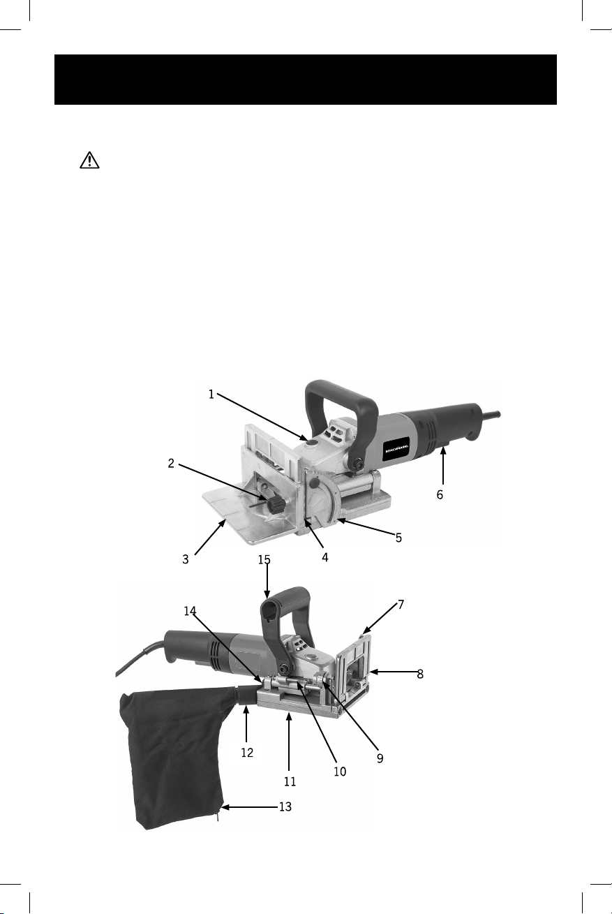
FUNCTIONS
1. Spindle Lock Button 2. Fence Lock Knob
3. Fence 4. Fence Height Scale
5. Angle 6. ON/OFF Switch
7. Fence Angle Lock 8. Faceplate
9. Depth Indicator 10. Depth Stop
11. Sliding Base 12. Dust Port
13. Dust Bag 14. Blade Access Knob
15. Auxiliary Handle

ASSEMBLY
ATTENTION: Read the entire important safety information section at the
beginning of this manual Including all text under subheadings therein before set up
or use of this product.
CONTROLS & COMPONENTS
ATTENTION:
Refer to Figures 1 & 2 and the following
descriptions to become familiar with the basic
controls of this tool.
A. Spindle Lock Button: When pressed, locks
spindle for removing/replacing blade.
B. Fence Lock Knob: Locks fence at desired
height of cut.
C. Fence: Orients tool to workpiece at specified angle.
D. Fence Height Scale: Indicates distance between center of blade and bottom of
fence.
E. Angle Scale: Indicates angle of cut.
F. ON/OFF Switch: Starts and stops motor. Tool
will remain running while switch is held until
released.
G. Dust Port: Connects dust extraction system
to blade housing and prevents dust build up
during cutting operations.
H. Sliding Base: Houses blade. Spring action
retracts blade after cut.
I. Depth Stop: Contacts turret stop during
operation, limiting depth of cut.
J. Depth Indicator: Six-position turret for selecting biscuit cut depth
(0, 10, 20, S, D, and MAX).
K. Faceplate: Contacts edge of workpiece at desired location of biscuit groove.
L. Angle Lock: Locks faceplate to desired angle of cut.
WARNING
Always disconnect this tool from the power supply
before attaching or removing accessories, or making
any adjustments.
TO ASSEMBLE TOOL:
1. Loosen fence lock knob, and slide fence onto
faceplate (see Figure 6).
2. Tighten fence lock knob (see Figure 6) The
machine is equipped with a 1" dust port that can
attach to a dust collection system (not included)
or the included dust bag.
11
D
A
B
CE
F
Fig.1: Fence adjustment and power controls
Fig.2: Depth adjustment, angle lock,
and dust port.
Fence
Lock
Knob
Fig.6: Fence attached to faceplate.
Fence
Faceplate
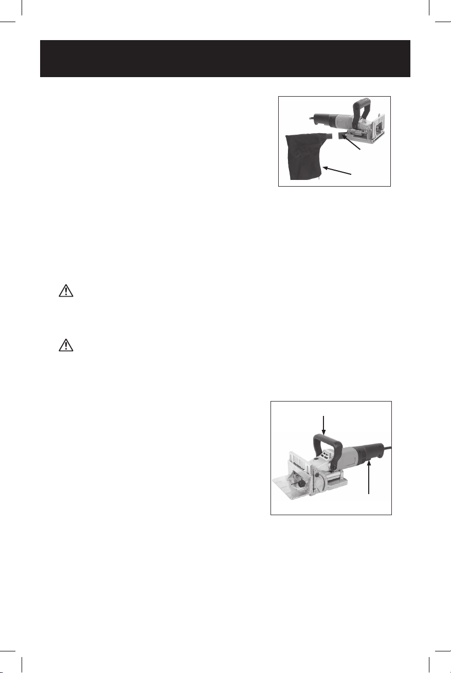
TO INSTALL DUST BAG:
1. Push plastic end of dust bag into dust port, as
shown in Figure 7.
2. Verify dust bag is closed before operating tool.
Note: If using the dust bag, remove and clean out
on a regular basis. Ideally, empty the dust bag
when it is half full.
TEST RUN
Once assembly is complete, test run the tool to ensure it is properly connected
to power and safety components are working properly.
If you find an unusual problem during the test run, immediately stop the tool,
disconnect it from power, and fix the problem BEFORE operating the tool again.
The Troubleshooting table in the SERVICE section of this manual can help.
The test run consists of verifying the following:
1) The motor powers up and runs correctly.
ATTENTION
Serious injury or death can result from using tool BEFORE understanding its
controls and related safety information. DO NOT operate, or allow others to operate,
tool until information is understood.
ATTENTION
DO NOT start tool until all preceding setup instructions have been performed.
Operating an improperly set up tool may result in malfunction or unexpected results
that can lead to serious injury, death, or tool/ property damage.
TO TEST RUN TOOL
1. Clear away all setup/adjustment tools.
2. Verify blade is properly installed
(see Changing Blade on Page 17).
3. Connect tool to power supply.
4. While firmly holding auxiliary handle (see Figure
8) in one hand, squeeze ON/OFF switch with
opposite hand. Motor should run smoothly and
without unusual problems or noises.
5. Release ON/OFF switch. Motor should
immediately stop running.
1261-000
BISCUIT JOINER
12
Fig. 8: Location of auxiliary handle and
ON/OFF switch
Auxiliary handle
ON/OFF switch
Fig.7: Installing dust bag into dust port
Dust Port
Dust Bag

OPERATION
ATTENTION
To reduce risk of eye injury from flying chips or lung damage from breathing dust,
always wear safety glasses and a respirator when operating this tool.
ATTENTION
If you are not experienced with this type of tool, we strongly recommend that you
seek additional training outside of this manual. Read books/magazines or get formal
training before beginning any projects. Regardless of the content in this section,
Benchmark tool will not be held liable for accidents caused by lack of training.
TURNING TOOL ON/OFF
• To start the tool squeeze the On/O Trigger Switch
• Release the On/O Trigger Switch to turn o
ADJUSTING DEPTH OF CUT
The biscuit joiner can be adjusted to cut slots for standard #0, #10 and #20
biscuits, simplex fittings, and duplex hinges. Refer to the table in Figure 9 to
determine biscuit size and cutting depth.
Biscuit # Material
Thickness (mm)
Cut Depth
(mm)
Depth Indicator
Marking
#10 4 8 0
#10 4 10 10
#20 4 12.5 20
Simplex 4 13 S
Dimplex 4 15 D
N/A N/A 18 Max
SETTING CUTTING DEPTH
1. Rotate depth indicator (see Figure 10) until
desired depth marking on indicator aligns
with arrow mark.
13
Fig 10. Depth indicator aligned with arrow mark
Depth indicator Arrow mark
Fig 9. Buiscut cut depth and depth scale marking table

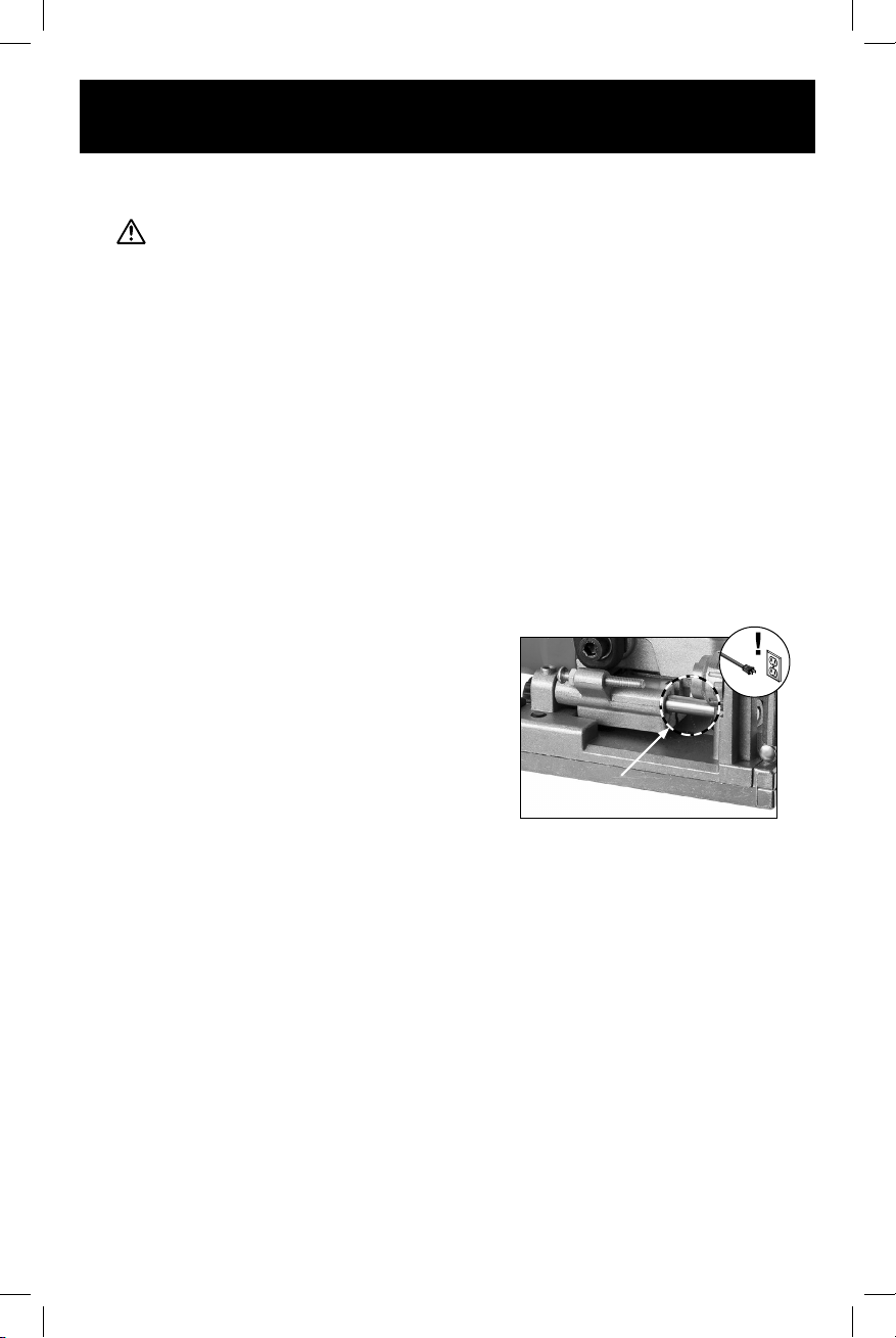
ADJUSTING CUTTING DEPTH
1. DISCONNECT TOOL FROM POWER!
2. Rotate depth indicator until position "10"
is aligned with arrow mark.
3. Push forward on auxiliary handle until depth
stop contacts depth indicator and measure
length of exposed blade from blade tooth tip
to sliding base.
Note: Rotate saw blade until blade tooth tip is
centered at the maximum distance from the
sliding base.
4. Verify depth measurement as follows:
• If measurement equals 10mm, the cutting depth is properly calibrated.
• If measurement does not equal 10mm, loosen depth stop lock nut
(see Figure 11).
WARNING:
Failure to correctly adjust the cutting depth could cause damage to the workpiece.
Note: Always make a trial cut on scrap material to confirm the settings and reduce
or extend depth stop until measurement equals 10mm. Tighten depth stop lock nut
once depth is reached.
ADJUSTING CUTTING ANGLE
The faceplate can be adjusted between 0° and 90°,
though 90° is the most common angle of cut for
biscuit joining. Certain applications, such as joining
beveled edges, require the biscuit to be inserted at
Note: Ball and groove detents on the angle scale
are provided to set the angle at 0°, 45°, and 90°.
To adjust cutting angle:
1. Release angle lock (see Figure 12).
2. Tilt faceplate until desired angle on scale lines
up with arrow mark.
3. Tighten angle lock.
ADJUSTING CUTTING HEIGHT
The fence can be adjusted to a height of 0-40mm.
Cutting height depends on your workpiece
thickness. Set the cutting height to half the
thickness of your workpiece for the strongest joint.
To adjust cutting height.
1. Set faceplate angle to 90°
(see Adjusting Cutting Angle above).
1261-000
BISCUIT JOINER
14
Fig 11. Location of cutting depth
adjustment components.
Lock Nut
Depth Stop Depth
Indicator
Fig 12. Location of cutting angle
adjustment components.
Angle Lock
Angle Scale
Fence
Lock
Knob
Arrow Mark
Fence Height Scale
Fig 13. Location of cutting height
adjustment components.
2. Loosen fence lock knob and move fence up or down on faceplate until arrow
mark on angle scale aligns with desired height on fence height scale
(see Figure 13).
3. Tighten fence lock knob once desired height is reached.
WORKPIECE PREPARATION
Properly mark your workpieces to avoid incorrect biscuit placement
and wasted material.
The following example illustrates a typical biscuit joining layout.
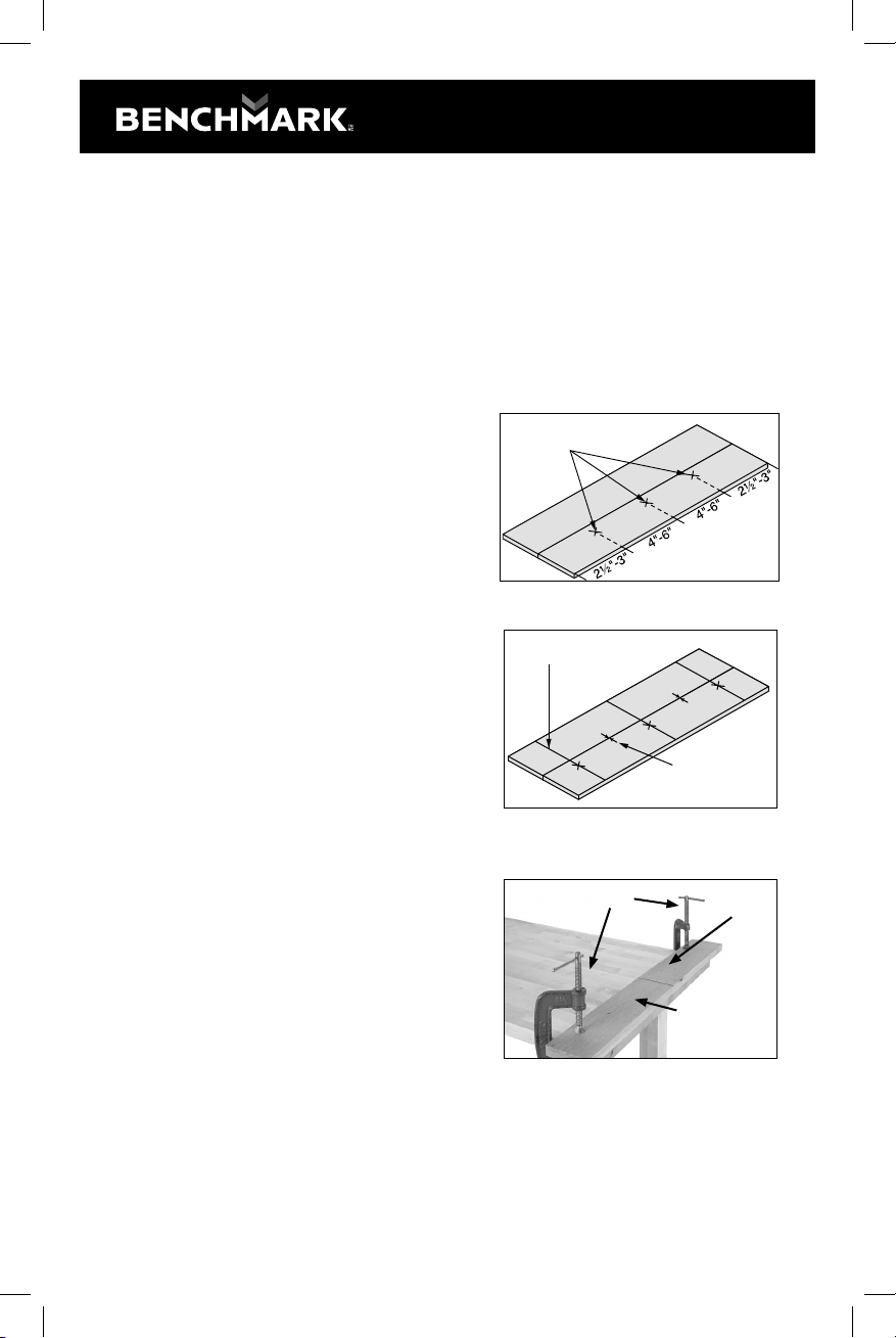
LAYING OUT CUTS
1. Place edges of (2) workpieces flush against
each other on a smooth, flat surface. Verify
board ends line up.
2. Place marks 2 1/2”- 3” from each end of one
board. Note: If distance between marks is
greater than 6", place additional marks at
4"-6" intervals (see Figure 14).
3. Use a square to draw layout lines across
boards through marks, then make
registration marks on edge of each boar
to ensure correct edge is cut
(see Figure 15).
SECURING WORKPIECE
Your workpiece must be properly secured
before making cuts. Cutting biscuit grooves with
a biscuit joiner places pressure on the edge of
the workpiece, which can cause an improperly
secured workpiece to shift on the workbench,
resulting in personal injury or damage to the
tool or workpiece.
Use clamps to secure workpiece on work-
bench. Edge of workpiece should hang slightly
over edge of workbench (see Figure 16).
Note: Clamps should be placed at least 3"
from any cut marks to prevent interference with
joiner.
15
Fig 15. Layout lines and registration marks.
Layout lines
Registration marks.
Fig 14. Biscuit location marks
Marks
Fig 16. Example of workpiece setup.
Workpiece
Center Line
Clamps

TO CUT BISCUIT GROOVES
1. Place fence on workpiece so front groove and
rear groove line up with layout line, as shown
in Figure 17. Make sure faceplate contacts
edge of workpiece.
2. Turn biscuit joiner ON and allow motor to
reach full speed.
3. With both hands holding tool, slowly push
blade into workpiece, as shown in Figure 18,
making sure joiner grooves remain aligned
with layout line on workpiece, as described
in Step 1.
4. Once blade reaches full depth, slide joiner
body backward, allowing blade to retract
into base plate.
5. Turn joiner OFF and wait for motor to come
to a complete stop before setting tool down.
GLUING BISCUITS
Once all biscuit grooves have been cut, test-fit biscuits with a "dry fit" prior to
the glue-up. Place a biscuit in each groove, and fit the pieces together to check
for proper alignment.
Once a proper fit is verified, apply glue to workpiece edges and grooves, insert
biscuits into grooves, then clamp according to the needs of the material and
the glue manufacturer's instructions.
CHANGING BLADE
This tool accepts 4" blades with either a 20mm or 22mm bore, depending
on the position of the inner flange.
ATTENTION
To reduce risk of injury, always disconnect power from joiner before changing
blades. Since blade is sharp, use extra care and wear gloves when installing it.
1261-000
BISCUIT JOINER
16
Fig 17. Biscuit joiner aligned with workpiece.
Front Groove
Layout Lines
Rear Groove
Fig 18. Biscuit joiner operation

TO CHANGE BLADE:
1. DISCONNECT TOOL FROM POWER!
2. Loosen fence lock knob and then slide fence up
to remove it from faceplate (see Figure 19).
3. Turn tool over so bottom of sliding base is
facing upward.
4. Loosen blade access knob (see Figure 20) until
the sliding base lid can be raised.
5. Press spindle lock button (see Controls &
Components on Page 10) and use spanner
wrench to turn outer flange until spindle lock
engages spindle (see Figure 21).
6. Continue to press spindle lock button, and use
spanner wrench to loosen outer flange.
7. Remove blade and outer flange from spindle.
Note: If switching between blades with 20mm and
22mm bores, flip inner flange over before installing
new blade to accommodate change in bore size
(see Figure 22).
8. Install new blade, verify teeth face correct direction for rotation of spindle, as
shown in Figure 23
9. Place outer flange on spindle, press spindle
lock button, and tighten outer flange with
spanner wrench.
10. Close sliding base lid and tighten blade
access knob.
11. Install fence to desired height, as shown in
Adjusting Cutting Height on Page 13.
17
Fence
Faceplate
Fig. 19. Fence removed from faceplate
Fig. 20. Loosening blade access knob.
Sliding Base
Blade
Access
Knob
Out
Flange
Fig. 21. Removing blade with spanner wrench
Fig. 23. Blade installed with teeth
correct direction.
Inner
Flange
Blade
Spindle
Outer
Flange
Fig. 22. Proper orientation
of blade components for assembly.
MAINTENANCE
ATTENTION
Always DISCONNECT POWER before servicing, adjusting, or doing maintenance
to reduce risk of accidental injury or electrocution.
For optimum performance from this tool, routinely check the condition of the
following items and repair or replace as necessary.
• Loose bolts
• Damaged bits
• Worn or damaged wires
• Any other unsafe condition
CLEANING
Use a brush and a shop vacuum to remove wood chips and other debris from the
tool, particularly from around the blade slot on the sliding base. Never blow o
the tool with compressed air, as this could force wood chips deeper into the motor
vents. Use a clean cloth to wipe away any dust remaining after each operation.
Note: DO NOT use caustic cleaners on plastic parts. If dry cleaning is insucient,
a mild detergent on a damp cloth is recommended.
Keep water away from tool at all times.
LUBRICATION
Periodically lubricate all moving parts with a light
machine oil as needed. Place a drop of oil on the
guide rails on both sides of the sliding base (see
Figure 27), then slide the base back and forth,
working the oil across the rails. Use a clean rag to
wipe o any excess oil, which can collect sawdust
or stain the workpiece.
REPLACING BRUSHES
This tool is equipped with a universal motor that uses two carbon brushes to
transmit electrical current inside the motor. These brushes are considered to be
regular "wear items" or "consumables" that will need to be replaced during the life
of the motor. The frequency of required replacement is related to how much the
motor is used and how hard it is pushed. Replace both carbon brushes at the same
time when the motor no longer reaches full power, or when the brushes measure
less than 1/4" long (new brushes are 5/8" long).
1261-000
BISCUIT JOINER
18
Fig. 27. Location of sliding base
guide rail (1 of 2).
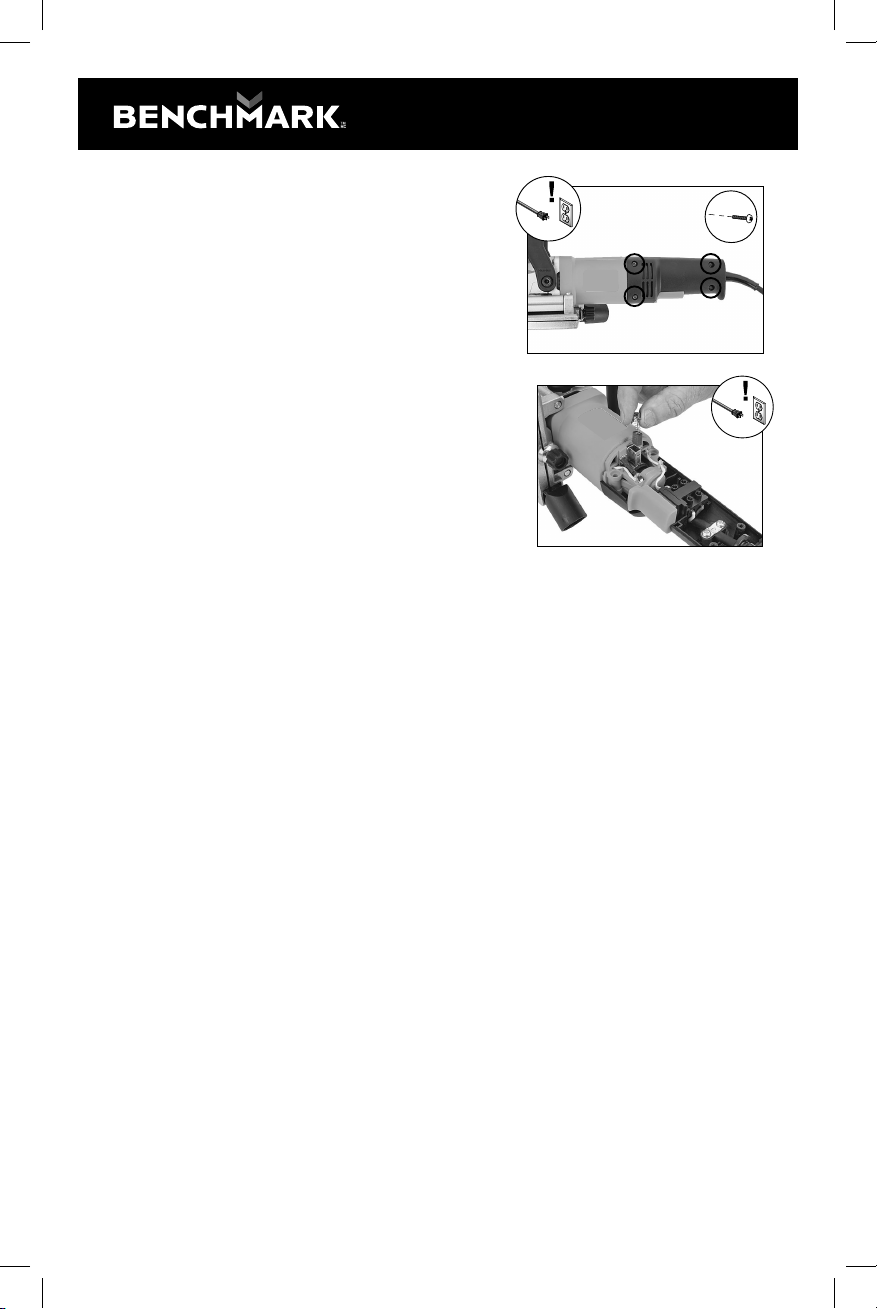
TO REPLACE MOTOR BRUSHES:
1. DISCONNECT TOOL FROM POWER!
2. Remove (4) tap screws from left side of main
joiner handle (see Figure 28), and separate
both sides of handle.
Note: Make sure not to pull on or damage
the wires located in main handle during
disassembly.
3. Locate and remove (2) motor brushes
(see Figure 29).
Note: If removing the brushes by hand is
too dicult, carefully use a small screwdriver
to push down on the brush holder tabs to
release them.
4. Replace motor brushes and install main handle
19
x4
Fig. 28. Location of main handle fasteners
Fig. 29. Replacing motor brush (1 of 2)
Table of contents


