Bender MIP Series User manual

Isolated Power Panels
For Healthcare Facilities
NAE209501-2 / 02.2019
T M
EN Manual

Bender Inc.
USA:
420 Eagleview Blvd.
Exton, PA 19341
Toll Free: 800-356-4266
Phone: 610-383-9200
Fax: 610-466-2071
E-mail: info@bender.org
Canada:
5810 Ambler Drive, Unit 1
Mississauga, ON L4W 4J5
Toll Free: 800-243-2438
Phone: 905-602-9990
Fax: 905-602-9960
E-mail: [email protected]
Web: www.benderinc.com
NAE209501-2, 02.2019
© Bender Inc.
All rights reserved.
Content subject to change.
T M

3IP Panels © 2018 Bender Inc. All Rights Reserved
Table of Contents
1. Introduction......................................................................................... 5
1.1 Isolated Power Panels...................................................................... 5
2. Safety Instructions.............................................................................. 6
2.1 General Safety Warning .................................................................. 6
2.2 Using This Manual............................................................................. 7
3. Model Types ........................................................................................ 8
3.1 MIP / MIE Series Isolated Power Panels ..................................... 8
3.2 MIC Series Isolated Power Panels with Circuit Control........ 8
3.3 MID Series Dual Output Voltage Isolated Power Panels..... 9
3.4 MIX Series Dual System Isolated Power Panels...................... 9
4. Components ...................................................................................... 10
4.1 Backbox Package............................................................................. 10
4.2 Front Trim Package......................................................................... 11
4.3 Isolation Transformer Kit .............................................................. 11
4.4 Interior Package............................................................................... 12
4.5 Circuit Breakers ................................................................................ 13
4.6 Line Isolation Monitor (LIM) ........................................................ 14
4.7 Fault Location (EDS) Kit................................................................. 14
4.8 Receptacle Kit ................................................................................... 15
4.9 Load Monitoring.............................................................................. 15
4.10 Accessories Package....................................................................... 15
5. Receiving, Handling, and Storage................................................. 16
5.1 Receiving............................................................................................ 16
5.2 Handling............................................................................................. 16
5.3 Storage................................................................................................ 16
6. Pre-Installation Requirements ....................................................... 17
6.1 General Requirements................................................................... 17
6.2 Support Requirements.................................................................. 18
6.3 Size Requirements .......................................................................... 18
7. Installation ......................................................................................... 19
7.1 Considerations ................................................................................. 19

4 IP Panels © 2018 Bender Inc. All Rights Reserved
7.1.1 Distance From Finished Floor..................................................... 19
7.1.2 Available Conduit Areas ............................................................... 19
7.2 Mount Backbox................................................................................ 20
7.3 Install Conduit.................................................................................. 22
7.4 Install Interior ................................................................................... 23
7.5 Remove Interior Deadfront ......................................................... 24
7.6 Install Breaker Kit............................................................................. 25
7.6.1 Components..................................................................................... 25
7.6.2 Install Breaker Bracket Assembly............................................... 26
7.6.3 Install Breaker Sub-Plate............................................................... 27
7.7 Install Transformer.......................................................................... 28
7.7.1 Vibration Pads and Mounting Hardware................................ 28
7.7.2 Mounting ........................................................................................... 29
7.7.3 General Instructions....................................................................... 30
7.7.4 Transformer and Incoming Power Wiring.............................. 30
7.7.5 Branch Circuit Wiring..................................................................... 31
7.7.6 Grounding ......................................................................................... 32
7.7.7 Accessories / Add-On Kit Wiring................................................ 32
7.8 Wiring Diagrams.............................................................................. 33
7.8.1 MIP, MIE, and MIX Series............................................................... 33
7.8.2 MIC Series........................................................................................... 34
7.8.3 MID Series .......................................................................................... 35
7.9 Reinstall Interior Deadfront......................................................... 36
7.10 Install Front Trim ............................................................................. 37
7.10.1 Install U-Type Retaining Nuts ..................................................... 37
7.10.2 Mount Front Trim............................................................................ 38
7.10.3 Install Line Isolation Monitor ...................................................... 39
7.10.4 Install Transformer Heat Shield (MIX Series Only)............... 40
7.10.5 Install Lower Front Trim (MIX Series Only)............................. 41
7.10.6 Install Restraining Lanyard (MIX series only)......................... 41
7.10.7 Connect Line Isolation Monitor Harness ................................ 42
7.10.8 Close Front Trim .............................................................................. 42

Introduction
5IP Panels © 2018 Bender Inc. All Rights Reserved
1. Introduction
1. 1 Isolated Power Panels
Bender isolated power panels provide isolated, ungrounded power to electri-
cal systems in operating rooms and other critical areas in healthcare facilities.
Isolated power systems allow for early detection of hazardous current while
keeping the system online. The system gives a visual indication of the level of
current in milliamperes (mA). When the threshold is reached, a visual and audi-
ble alarm is activated.
An isolation transformer serves a single operating room, except when supply-
ing power to equipment requiring 150 VAC or higher. A line isolation monitor
(LIM) indicates possible leakage current from all isolated conductors to
ground.
This manual provides instructions on installing and operating isolated power
panels. Refer to all relevant national and local codes and standards before pro-
ceeding with installation.

6 IP Panels © 2018 Bender Inc. All Rights Reserved
Safety Instructions
2. Safety Instructions
2. 1 General Safety Warning
Hazard of Electric Shock, Burn, or Explosion
Only qualified maintenance personnel should operate or service this equip-
ment. These instructions should not be viewed as sufficient for those who are
not otherwise qualified to operate or service this equipment. No responsibility
is assumed by BENDER for any consequences arising from use of this docu-
ment.
Turn OFF all sources of electric power before performing any inspections, tests,
or service on this equipment. Assume all circuits are live until they have been
properly de-energized, tested, grounded, and tagged. Failure to observe these
precautions will result in equipment damage, severe personal injury, or death.
Proper operation of this equipment depends on proper installation. Refer to
NFPA 70, NFPA 70E, CSA Z462, and other relevant standards and codes for
installation standards. Neglecting fundamental installation techniques will
result in equipment damage, severe personal injury, or death.
Do not make any modifications to the equipment. Failure to observe this pre-
caution will result in equipment damage or personal injury.
Use only manufacturer’s and manufacturer recommended accessories with
this equipment. Failure to do so may damage the equipment beyond repair.
!
DANGER

Safety Instructions
7IP Panels © 2018 Bender Inc. All Rights Reserved
2. 2 Using This Manual
Read these instructions carefully and become familiar with the equipment
before attempting to install, operate, or service it. Throughout this manual,
special messages may appear to warn of potential safety hazards or to call
attention to information which clarifies instructions or procedures. Observe all
safety messages that appear throughout this manual to avoid possible injury
or death. An explanation of these symbols is given below.
DANGER: Indicates a hazardous situation which, if
not avoided, will result in death or severe injury.
WARNING: Indicates a potentially hazardous situa-
tion which, if not avoided, may result in death or injury.
CAUTION: Indicates a potentially hazardous situation
which, if not avoided, may result in injury or equipment
damage.
NOTE: Provides additional information to clarify in-
structions for a product or procedure.
D
AN
G
ER
WARNIN
G
C
A
U
TI
O
N

8 IP Panels © 2018 Bender Inc. All Rights Reserved
Model Types
3. Model Types
3. 1 MIP / MIE Series Isolated Power Panels
Single-system, single-output-voltage isolated
power panel. MIP designation is used for pan-
els rated 10 kVA or below. MIE designation is
used for panels rated 15 kVA or above.
3. 2 MIC Series Isolated Power Panels with Circuit Control
Single-system, single-output-voltage (of
at least 150 V) isolated power panel. Pro-
vides programmable control of up to
twelve (12) individual circuits. Commonly
used with 208 VAC or 240 VAC portable
medical equipment, such as lasers. Circuit
control logic is configured at the factory.

Model Types
9IP Panels © 2018 Bender Inc. All Rights Reserved
3. 3 MID Series Dual Output Voltage Isolated Power Panels
Isolated power panel for a single-input-
voltage and dual-output-voltage system.
Commonly used to simultaneously supply
power to both normal line powered
equipment and equipment operating at a
voltage greater than 150 VAC (such as por-
table medical lasers).
3. 4 MIX Series Dual System Isolated Power Panels
Two MIP series interiors installed side-by-
side in a common enclosure. In figure
below, the transformer access front trim is
translucent for illustration purposes.
Wire is provided with the front trim
assembly for ground bus interconnection
and transformer terminal block connec-
tions to panel board lugs (or sub-feed
lugs, if applicable).

10 IP Panels © 2018 Bender Inc. All Rights Reserved
Components
4. Components
The following sections describe key components of isolated power panels.
These components are standard for the United States unless otherwise noted.
Ensure equipment conforms to all national and local codes and standards
prior to purchasing.
4. 1 Backbox Package
The backbox meet the requirements of NEMA
Type 1 according to UL 50. It is fabricated from a
minimum 14 GA galvanized steel and is
designed for flush (recessed) or surface mount-
ing. Flush mounting is standard. Surface
mounted backboxes must be requested during
the purchasing process.
Surface mounted backboxes are finished with a
coat of hospital grade ivory baked enamel or
equivalent.
All backboxes include an easy-lift-off hinge
assembly to ease front trim installation and sys-
tem maintenance.

Components
11IP Panels © 2018 Bender Inc. All Rights Reserved
4. 2 Front Trim Package
The front trim is manufactured from a minimum
14 GA, type 304 stainless steel. It contains a door
with hidden hinges and flush mounted key lock.
The door provides access to circuit breakers and
optional fault location (EDS) accessories if
equipped. Most front trims are provided with
provisions for future field installation of recepta-
cle and/or fault location assembly kits.
Front trims may be used with flush-mounted or
surface-mounted backboxes. For flush mounted
panels, the front trim extends 1”(25.4 mm) on
all sides of the backbox. For surface-mounted
panels, the front trim has the same height and
width as the backbox.
4. 3 Isolation Transformer Kit
The isolation transformer kit contains the fol-
lowing:
• Transformer and mounting hardware
• Primary main circuit breaker and bracket
assembly
• Secondary main circuit breakers (where
applicable)
• Breaker sub-plate and mounting hardware
Isolation transformers used in isolated power
systems are special-purpose, low-voltage, dry-
type transformers. They are application-specifi-
cally designed and fulfill the requirements of UL
5085 and UL 1047.
The primary main breaker, mounting hardware,
and sub-plate are included in the isolation trans-
former kit. For MID series panels (and custom
configurations where applicable), the isolation
transformer kit will also include secondary main
circuit breakers.

12 IP Panels © 2018 Bender Inc. All Rights Reserved
Components
4. 4 Interior Package
The interior assembly is a single, factory-wired
sub-panel containing one or more of the follow-
ing (varies by configuration):
• Distribution panel with branch circuit
breaker load center
• Equipment ground bus
• LIM2010 line isolation monitor and connec-
tor plate
• Accessory kits per project documents
Per project specifications, interior packages may
also include any of the following accessories /
accessory kits:
• Transformer load monitoring (STW kit)
• Branch circuit fault location (EDS kit)
• Receptacle and ground jack kit (GPMP)
• Communication gateway (COM465IP)

Components
13IP Panels © 2018 Bender Inc. All Rights Reserved
4. 5 Circuit Breakers
All panels utilize two-pole, thermal magnetic cir-
cuit breakers. Panels ordered with selective
coordination may include an electronic trip ele-
ment added to the primary and/or secondary
main circuit breakers to achieve 0.1 second sys-
tem coordination.
The primary and secondary (where applicable)
main circuit breakers are sized to protect the
transformer coil. The primary main circuit
breaker is sized at 125% of rated current. Any
supplied secondary main circuit breakers are
sized at rated coil ampacity.
The quantity and rating of branch circuit breakers varies by panel:
• MIP and MIE series: Provided with sixteen (16) factory-installed 20 A
branch circuit breakers (unless otherwise stated).
• MIC series: Quantity and ampacity of branch circuit breakers is provided
according to project documents. The maximum allowed is twelve (12).
The logic for simultaneously energized branch circuits is configured at the
factory per project specifications.
• MID series: Output voltage 1 (designated as the “low side”) is provided
with sixteen (16) factory-installed branch circuit breakers. Output voltage
2 (designated as the “high side”) is provided with either one (1) or two (2)
factory-installed branch circuit breakers. Ampacity is per project specifica-
tions
NOTE: To maintain compliance with UL 1047, branch
breakers must not exceed 60 A.

14 IP Panels © 2018 Bender Inc. All Rights Reserved
Components
4. 6 Line Isolation Monitor (LIM)
All panels are supplied with one or more line
isolation monitor (LIM). The LIM monitors the
system impedance to ground of the entire iso-
lated power system. The impedance to ground
is used to calculate the total hazard current
(THC), given in units of milliamperes (mA).
The factory default THC alarm is set to 5 mA. The
value may be changed to 2 mA to meet applica-
ble certification requirements.
The LIM is installed on the front trim in a conspicuously visible location. Refer
to LIM user manual for more information on operation and use.
4. 7 Fault Location (EDS) Kit
Panels may include branch circuit fault location
as part of an optional accessory kit (EDS kit). The
system works together with the LIM2010 to
assist in identifying the specific circuit contribut-
ing to the total hazard current alarm. Fault loca-
tion is automated (unless otherwise configured)
once the total hazard current alarm is activated.
The EDS kit is installed in the interior assembly
and may be installed at the factory or on site.
Refer to panel add-on user manual for more
information on installation, operation, and use.

Components
15IP Panels © 2018 Bender Inc. All Rights Reserved
4. 8 Receptacle Kit
Panels may include on-board receptacles and
ground jacks as part of an optional accessory kit
(receptacle kit). The receptacle kit provides
NEMA type receptacles and/or hospital grade
ground jacks accessible directly from the front
trim. Type and quantity is per project specifica-
tions.
The receptacle kit is installed in the interior
assembly and may be installed at the factory or
on site. Refer to panel add-on user manual for
more information on installation, operation, and
use.
4. 9 Load Monitoring
Panels may include one or both of the following
load monitoring systems:
• Full system monitoring: The STW3 connects
to the line isolation monitor and monitors
the current draw of the full system. The LIM
can alarm once a set threshold is reached.
• Branch monitoring: Two CMS460 series
devices monitor the load current for each
individual circuit branch.
4. 10 Accessories Package
Refer to applicable documentation for any additional accessories included
with the panel.

16 IP Panels © 2018 Bender Inc. All Rights Reserved
Receiving, Handling, and Storage
5. Receiving, Handling, and Storage
5. 1 Receiving
Inspect all equipment immediately upon delivery. If any damage or mishan-
dling has occurred, file a damage claim with Bender and/or the carrier. Verify
packing slip details before filing a shortage claim.
Isolated power panels are typically packaged and shipped as four (4) separate
components:
• Backbox
• Interior assembly
• Transformer kit
• Front trim
These system components may be shipped at different times to accommodate
the installer project schedule. In many cases, the backbox and interior assem-
bly arrive first to allow sufficient time for preliminary installation.
5. 2 Handling
5. 3 Storage
• Do not store equipment in dusty or damp locations.
• Do not stack panels or equipment.
• Do not rest or lean front trims against walls.
NOTE: Do not separate the contents of the isolation
transformer kit until ready for installation.
WARNING: Due to the heavy load of isolated power
equipment, use suitable equipment for lifting and
transporting. Failure to do so may result in severe per-
sonal injury and damage to equipment.
WARNIN
G

Pre-Installation Requirements
17IP Panels © 2018 Bender Inc. All Rights Reserved
6. Pre-Installation Requirements
6. 1 General Requirements
Review all code, standards, and project requirements thoroughly before pro-
ceeding with installation.
Of particular importance is minimizing the cumulative system leakage current
in an isolated power system. NFPA 99 mandates an isolated power system’s
total line-to-ground insulation impedance shall exceed 200 kΩ. Excessive leak-
age current may result in non-conformance with this requirement.
NOTE: In addition to adhering to all national, local,
and project-specific requirements, the installer shall
thoroughly review and understand all information
within this manual and relevant reference material.
Applicable material includes, but is not limited to:
• NFPA 99 - 2012: Healthcare Facilities Code Chapter 6
• NFPA 70: National Electric Code (NEC), Article 517
• (Canada) CSA C22.1: Canadian Electrical Code (CEC,
CE-Code), Section 24
• (Canada) CSA Z32: Applications of Electricity in
Healthcare

18 IP Panels © 2018 Bender Inc. All Rights Reserved
Pre-Installation Requirements
6. 2 Support Requirements
Prior to installation, ensure the proper structural support will be used. Mini-
mum load bearing requirements are listed in the table below. For panels
weighing in excess of 500 lb (230 kg), install both horizontal (bottom) and ver-
tical (side) supports.
6. 3 Size Requirements
Verify backbox dimensions on label. Ensure the wall space required is available
before proceeding with backbox installation. Ensure the mounting style (sur-
face or flush) is correct for the application. For reference, standard backbox
sizes are listed in the table below. Dimensions are given in inches (cm).
NOTE: Custom configurations may have special
weight and load bearing requirements.
Type Weight (lb) Weight (kg)
MIP series 370 168
MIE series 650 295
MIC series 650 295
MID series 675 306
MIX series 700 317
Model Height Width Depth
B662406(S) 66” (167.6 cm) 24” (61 cm) 6” (15.2 cm)
B662408(S) 66” (167.6 cm) 24” (61 cm) 8” (20.3 cm)
B723012(S) 72” (182.9 cm) 30” (76.2 cm) 12” (30.5 cm)
B723014(S) 72” (182.9 cm) 30” (76.2 cm) 14” (35.6 cm)
B803608(S) 80” (203.2 cm) 36” (91.4 cm) 8” (20.3 cm)

Installation
19IP Panels © 2018 Bender Inc. All Rights Reserved
7. Installation
7. 1 Considerations
7.1.1 Distance From Finished Floor
Refer to table below for allowable distances between bottom of isolated
power panel and finished floor.
7.1.2 Available Conduit Areas
Refer to figures below. Shaded areas are allowable conduit locations.
Models Allowable Distance
MIP, MIC, MIE, MID Minimum 2’ (61 cm), maximum 20’ (610 cm)
MIX Minimum 2’ (61 cm), maximum 9’ (275 cm)
A 5” (127 mm)
B 2” (51 mm)
C 16” (405 mm)

20 IP Panels © 2018 Bender Inc. All Rights Reserved
Installation
7. 2 Mount Backbox
The manufacturer recommended mounting method is to secure the backbox
to a rigid support structure (strut channel, etc.) using minimum 5/16”commer-
cial grade hardware (not included). Mounting locations are near the four cor-
ners of the enclosure sidewalls. Refer to figure on the following page for
example location in the top left corner. Note the following requirements for
each corner:
• Use two (2) 5/16”fasteners per corner on the side wall of the backbox
• Must be 2” (51 mm) from the top of the backbox
• Must be 2” (51 mm) from the front of the backbox
• Screws must be 2”(51 mm) apart
For flush-mounted enclosures, install flush with finished wall or recessed no
more than 1/8”(3 mm).
NOTE: Before installing, check the part number to ver-
ify the backbox to be installed matches with the appro-
priate interior, transformer kit, and front trim. Most
backboxes are identical in appearance.
CAUTION: Do not over-tighten the mounting hard-
ware. Over-tightening will cause distortion, misalign-
ment of the front trim, and improper hinge
functionality. Use shims to mitigate distortion as need-
ed.
NOTE: Recessing enclosure more than 1/8” (3 mm) will
impede hinge functionality.
C
A
U
TI
O
N
This manual suits for next models
14
Table of contents
Other Bender Portable Generator manuals
Popular Portable Generator manuals by other brands

Kodiak
Kodiak SGB12000HX Operating instructions and parts manual
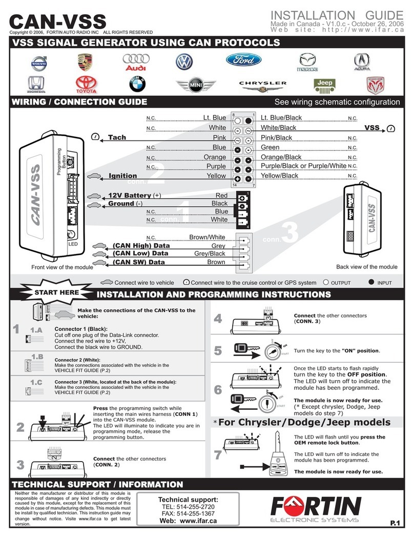
Fortin
Fortin CAN-VSS installation guide

AtmosAir
AtmosAir Matterhorn 1000 Series Installation, operation, maintenance guide
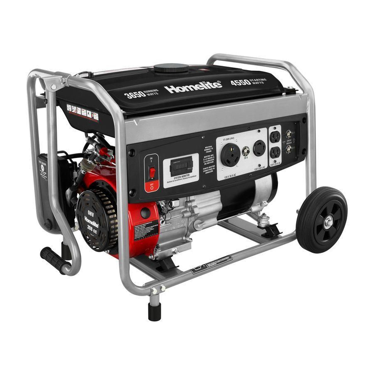
Homelite
Homelite UT903655DA Operator's manual

Fischer Panda
Fischer Panda 12000x PMS manual

Onan
Onan MEP-003A Technical manual
