BENDIX AD-4 AIR DRYER User manual

1
®
SD-08-2407
Bendix®AD-4™Air Dryer
EXTENDED PURGE AD-4™AIR DRYER STANDARD AD-4™AIR DRYER
LOWER
BRACKET
DESCRIPTION
ThefunctionoftheAD-4™airdryeristocollectand remove
air system contaminants in solid, liquid and vapor form be-
fore they enter the brake system. It provides clean, dry air
to the components of the brake system which increases
thelife ofthe systemand reducesmaintenance costs.Daily
manualdraining of thereservoirs is eliminated.
TheAD-4™airdryer consistsof a desiccantcartridgeand a
die cast aluminum end cover secured to a cylindrical steel
outer shell with eight cap screws and nuts. The end cover
containsacheckvalveassembly,asafetyvalve, purgevalve
mechanism, a cast-in heater element with a replaceable
thermostatassembly and three threadedairconnections.
The three air connections are identified with embossed
numbersandlettering.Theidentificationandfunctionofeach
is as follows:
Port l.D. Function/Connection
CON 4................ ControlPort
(fromunloaderportongovernor).
SUP 11 .............. Supply Port (air in).
DEL 2 ................ Delivery Port(air out).
A cast-in heater element and replaceable thermostat with
anexternal terminalare provided.
The voltage and wattage requirements of the heater and
thermostatareshown with embossed numbers andletters
in the recess adjacent to the control port marked “CON.”
UPPER
BRACKET
LOWER
BRACKET
PURGE
EXHAUST
FIGURE 1 - AD-4™AIR DRYER MODELS
SUPPLY
PORT
THERMOSTAT
TERMINAL
SUPPLY
PORT
CONTROL
PORT
DELIVERY PORT PURGE
EXHAUST
UPPER
BRACKET

2
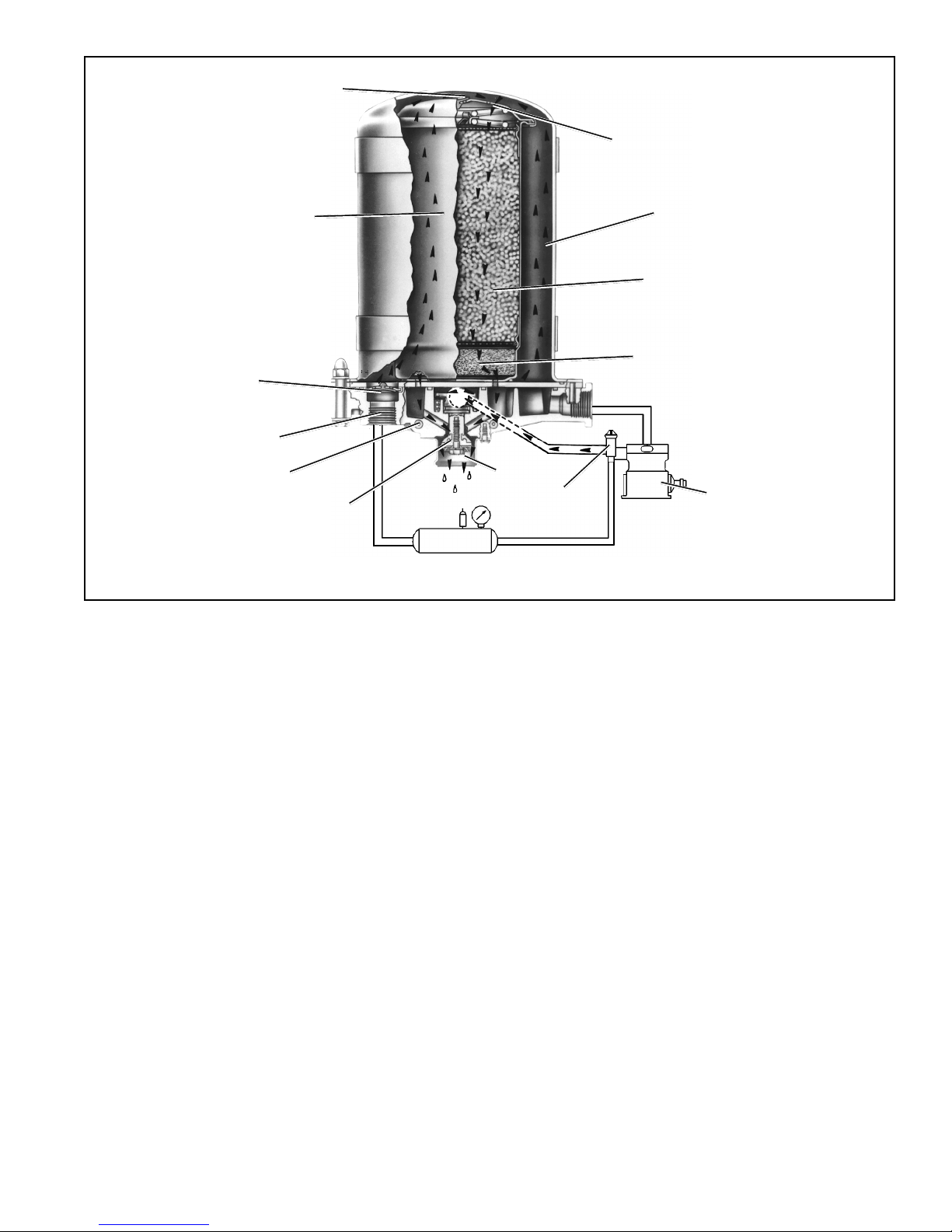
PURGE VOLUME
DESICCANT
BED
CHECK
VALVE
OIL SEPARATOR
DESICCANT
CARTRIDGE
DELIVERY
PORT
HEATER
CHECK
VALVE
PURGE
VALVE
ORIFICE
EXHAUST
PORT
SUPPLY RESERVOIR
CONTROL
GOVERNOR COMPRESSOR
OPERATION OF THE AD-4™AIR DRYER
The AD-4™air dryer alternates between two operational
modes or “cycles” during operation: the charge cycle and
the purge cycle. The following description of operation is
separatedinto these “cycles” ofoperation.
CHARGE CYCLE (refer to Figure 2)
When the compressor is loaded (compressing air)
compressed air, along with oil, oil vapor, water and water
vapor flows through the compressor discharge line to the
supplyportof theairdryer endcover.Theflow velocityorthe
speedat whichtheair andits contaminants traveldown the
discharge line is reduced substantially as it enters the air
dryerend coverbafflesystembehind thesupply port.Asair
travelsthroughthebafflesystem,itsdirectionofflowchanges
by 180 degrees several times, reducing the temperature,
causingcontaminantstocondense and drop to the bottom
orsump of the airdryerend cover.
After exiting the end cover baffle system, the air flows into
thedesiccant cartridge. Once in thedesiccantcartridge air
first flows through an oil separator which removes water in
liquid form as well as oil, oil vapor and solid contaminants.
FIGURE 2 - AD-4™AIR DRYER CHARGE CYCLE
Air exits the oil separator and enters the desiccant drying
bed.Air flowing through the column of desiccant becomes
progressivelydryeraswatervapor adherestothe desiccant
materialin aprocessknown as“adsorption”.Thedesiccant
cartridge using the adsorption process typically removes
95%of the watervapor from thepressurizedair.
Themajority of dryairexits the desiccantcartridge through
itsintegralsinglecheckvalvetofillthepurgevolumebetween
the desiccant cartridge and outer shell. Some air will also
exitthedesiccantcartridgethroughthepurgeorificeadjacent
tothe check valve.
Dry air flows out of the purge volume through the single
check valve assembly and out the delivery port to the first
(supply)reservoir of the airsystem.
The air dryer will remain in the charge cycle until air brake
system pressure builds to the governor cutout setting.
PURGE CYCLE (refer to Figure 3)
Whenair brakesystempressure reachesthe cutoutsetting
of the governor, the compressor unloads (air compression
stopped) and the purge cycle of the air dryer begins. The
3
FIGURE 3 - AD-4™AIR DRYER PURGE CYCLE
CONTROL
GOVERNOR
SUPPLY RESERVOIR
PURGE VOLUME
DESICCANT
BED
OIL SEPARATOR
DESICCANT
CARTRIDGE
DELIVERY
PORT
HEATER
CHECK
VALVE
PURGE
VALVE
COMPRESSOR
CHECK
VALVE
ORIFICE
EXHAUST
PORT
lineconnecting the governorunloaderport to theAD-4™air
dryerendcovercontrolportispressurizedwhenthegovernor
unloadsthe compressor.Airpressure attheAD-4™airdryer
end cover control port is also present on the purge valve
piston.The purge pistonmoves in responseto air pressure
causing the purge valve to open to atmosphere.
Contaminants in the end cover sump are expelled
immediately when the purge valve opens. Also, air which
wasflowingthroughthedesiccantcartridgechangesdirection
and begins to flow toward the open purge valve. Oil, water
and solid contaminants collected by the oil separator are
removedby air flowingfrom the desiccantdrying bed tothe
openpurgevalve.
Theinitialpurgeanddesiccantcartridgedecompressionlasts
onlya few secondsandis evidenced byanaudible burst of
air at theAD-4™air dryer exhaust.
The actual reactivation of the desiccant drying bed begins
asdryair flowsfromthe purgevolumethrough thedesiccant
cartridge purge orifice and into the desiccant drying bed.
Pressurizedairfromthepurgevolumeexpandsafterpassing
through the purge orifice; its pressure is lowered and its
volumeincreased.Theflowof dryair throughthedryingbed
reactivates the desiccant material by removing the water
vaporadhering to it. Generally15-30 seconds arerequired
forthe entire purgevolumeof astandardAD-4™airdryerto
flowthrough the desiccant dryingbed.
The end cover single check valve assembly prevents air
pressurein the brakesystemfrom returning totheair dryer
during the purge cycle.After the 30 second purge cycle is
complete,the air dryer is readyfor the next charge cycleto
begin.
The purge valve will remain open after the purge cycle is
completeandwill not close untilairbrake system pressure
is reduced and the governor signals the compressor to
charge.
PREVENTIVE MAINTENANCE
Important: Review the warranty policy before performing
anyintrusivemaintenanceprocedures.Anextendedwarranty
maybe voidedif intrusivemaintenanceis performedduring
thisperiod.
Becausenotwo vehiclesoperateunderidenticalconditions,
maintenanceandmaintenanceintervalswillvary.Experience
is a valuable guide in determining the best maintenance
intervalfor anyone particularoperation.

4
FIGURE 4 - AD-4™AIR DRYER SECTIONAL VIEW
DESICCANT
BED
OIL SEPARATOR
DESICCANT
CARTRIDGE
CHECK
VALVE PURGE
ORIFICE
EXHAUST
COVER
NUT
CHECK VALVE
ASSEMBLY
END COVER
HEX HEAD
SCREW
SPECIAL
WASHER DELIVERY
PORT PURGE
VALVE EXHAUST
DIAPHRAGM
O-RING
PURGE PISTON
SPRING
SEALING RING
SEALING RING
SEALING RING
SEALING RING
SUPPLY
PORT
PERFORATED PLATE
PURGE VOLUME
WASHER
Every900operating hours or 25,000milesor every three
(3)months:
1. Check for moisture in the air brake system by opening
reservoirs, drain cocks, or valves and checking for
presenceofwater. If moisture is present,thedesiccant
may require replacement; however, the following
conditions can also cause water accumulation and
shouldbe considered beforereplacingthe desiccant:
A. An outside air source has been used to charge the
system. This air did not pass through the drying bed.
B. Airusage is exceptionallyhighand not normal fora
highway vehicle. This may be due to accessory air
demandsorsome unusualairrequirementthatdoes
not allow the compressor to load and unload
(compressing and non-compressing cycle) in a
normal fashion. Check for high air system leakage.
If the vehicle vocation has changed it may be
necessaryto upgradethe compressorsize. Referto
AppendixA,TableAand thecolumnentitled Vehicle
Vocation.
C. The air dryer has been installed in a system that
has been previously used without an air dryer. This
type system will be saturated with moisture and
severalweeks ofoperationmay berequiredto dryit
out.
D. Location of the air dryer is too close to the air
compressor. Refer to LocatingAD-4™Air Dryer On
Vehicle section and AppendixA, TableA, column 2
fordischarge line length.
E. In areas where more than a 30 degree range of
temperature occurs in one day, small amounts of
water can accumulate in the air brake system due
to condensation. Under these conditions, the
presence of small amounts of moisture is normal
and should not be considered as an indication that
thedryer is notperformingproperly.
Note:Asmallamount ofoilinthesystem maybe normal
and should not, in itself, be considered a reason to
replacethe desiccant;oil staineddesiccant canfunction
adequately.
5
2. Check mounting bolts for tightness. Retorque to 270-
385inch pounds.
3. Perform the Operation & Leakage Tests listed in this
publication.
Every 10,800 hours or 300,000 miles or 36 months:
1. Rebuildthe air dryer includingthedesiccant cartridge.
Note:The desiccantchange intervalmayvary fromvehicle
to vehicle.Although typical desiccant cartridge life is three
years, many will perform adequately for a longer period of
time.In order to takemaximumadvantage of desiccant life
andassure that replacement occurs onlywhennecessary,
itisimportantthatOperation&LeakageTestsbeperformed.
WARNING!
This air dryer is intended to remove moisture and other
contaminants normally found in the air brake system.
Do not inject alcohol, anti-freeze, or other de-icing
substances into or upstream of the air dryer. Alcohol
is removed by the dryer, but reduces the effectiveness
of the device to dry air. Use of other substances can
damage the air dryer and may void the warranty.
OPERATION & LEAKAGE TESTS
1. Test the outlet port check valve assembly by building
the air system to governor cut-out and observing a test
airgauge installedinthe supplyreservoir.Arapid lossof
pressurecould indicate a failedoutlet port check valve.
(Note: Purgevalve will be openwhengovernor cut-out
pressure is reached. Allow 45 seconds after governor
cut-outoccurstocompletethepurgecyclebeforetesting
thecheck valve.)Coat theexhaustwith asoap solution.
Leakage should not exceed a 1" bubble in 1 second.
2. Check for excessive leakage around the purge valve.
Withthe compressorin loadedmode (compressingair),
apply a soap solution to the purge valve housing
assembly exhaust port and observe that leakage does
not exceed a 1" bubble in 1 second. If the leakage
exceedsthemaximumspecified, servicethepurgevalve
housingassembly.
3. Closeallreservoirdraincocks.Build upsystempressure
togovernorcut-outandnotethatAD-4™air dryerpurges
with an audible escape of air. “Fan” the service brakes
to reduce system air pressure to governor cut-in. Note
thatthe systemonceagain buildstofull pressureand is
followedby anAD-4™air dryerpurge.
4. Check the operation of the safety valve by pulling the
exposed stem while the compressor is loaded
(compressingair).Theremustbe anexhaustofairwhile
the stem is held and the valve should reseat when the
stem is released.
5. Check all lines and fittings leading to and from the air
dryerfor leakage andintegrity.
6. Check the operation of the end cover heater and
thermostat assembly during cold weather operation as
follows:
A. Electric Power to the Dryer
With the ignition or engine kill switch in the ON
position, check for power at the dryer’s electrical
terminal using a voltmeter or test light. On a single
terminalAD-4™air dryer’s disconnect the lead wire
at the end cover terminal post. Place the test leads
on the lead wire and a GOOD vehicle ground. On
dualterminalAD-4™airdryer’sdisconnect bothlead
wires at the end cover terminal posts. If there is no
voltageindicated,lookforablownfuse,brokenwires,
orcorrosion in the vehicle wiringharness.Check to
see if a good ground path exists.
B. ThermostatandHeaterOperation
Turn off the ignition switch and cool the end cover
assemblytobelow40degreesFahrenheit.Using an
ohmmeter, check the resistance between the
electricalterminalandthemetalendcover(seeFigure
5).(Note:Onthe dualterminal endcover,check the
resistance between the two terminals.) The
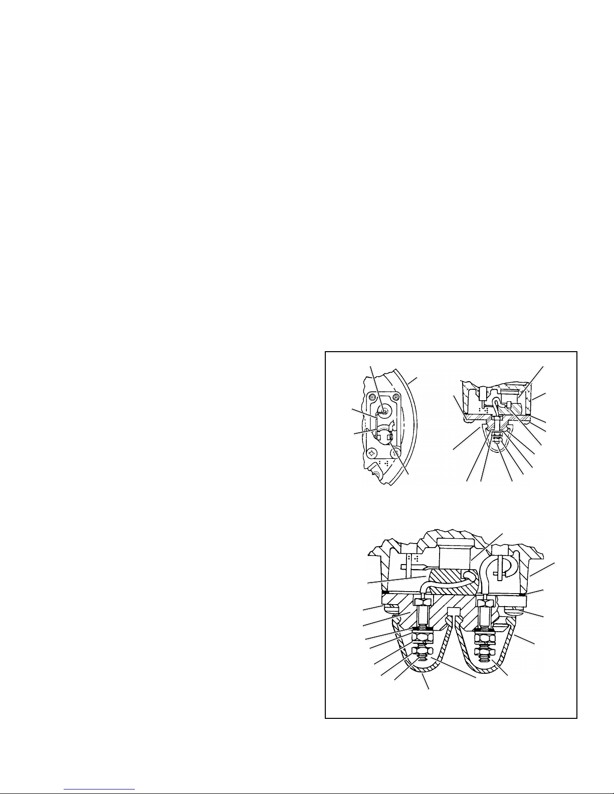
FIGURE 5 - AD-4™AIR DRYER SINGLE AND DUAL
TERMINAL THERMOSTAT ASSEMBLIES
DUAL WIRE SYSTEM
BOOT
7
10
9
1
11
8
6
1CONNECTIONS FOR POWER
AND INSULATED RETURN
BOOT
32
4
5
BOLD NUMBERS ARE ITEMS IN MAINTENANCE KITS
SINGLE WIRE SYSTEM
1
9
8
1
9
2
1
46117
10
THERMOSTAT
COVER
53
A
B
HEATER POST

6
resistanceshould be 2.0to 4.0 ohmsfor the 12volt,
60watt end coverand 4.0 -7.0 ohms forthe 24 volt,
120 watt end cover. These resistance values apply
toeither singleor dualterminalair dryerend covers.
Warm the end cover assembly to over 90 degrees
Fahrenheitandagainchecktheresistanceasabove.
The resistance should exceed 1000 ohms for both
singleand dual terminal air dryers.Ifthe resistance
values obtained are within the stated limits, the
thermostatandheaterassemblyisoperatingproperly.
If the resistance values obtained are outside the
stated limits, proceed to Step C to determine the
cause.
C. HeaterElementInspection
Withtheignitionorenginecontrolswitch“off”, remove
the thermostat cover (see Figure 5). Using an
ohmmeter, checkthe resistance betweenthe metal
endcoverandtheheaterpost(see Figure5). (Note:
Onthedual terminalend cover,checkthe resistance
between the two terminals.) For a 12 volt, 60 watt
end cover, the resistance should be 2.0 - 2.8 ohms
andfor a24 volt,120 wattend cover,4.0 -5.6ohms.
Theseresistancevaluesapplyto eithersingleordual
terminalairdryer endcovers.If theheaterresistance
value obtained is outside the stated limits, a new or
remanufacturedendcover shouldbe installed,since
the heater element cannot be serviced. Check that
agood groundpath existsbetween theair dryerend
cover casting and the vehicle chassis. Correct if
needed. If the heater resistance value obtained is
within the stated limits the thermostat should be
replaced (Kit Number 102657) or a new or
remanufacturedend coverinstalled. Note: The dual
terminalair dryercoverrequires kitnumber 103982.
D. Reassembly
Reinstallthethermostat coverasillustratedinFigure
5. Take special care to assure the rubber spacer
and the gasket are correctly installed, to assure
properoperation.
REBUILDING THE AD-4™AIR DRYER
GENERAL
If,after completing theroutine operationandleakage tests,
ithas beendetermined that oneor morecomponents ofthe
airdryer requires replacement ormaintenance, refer tothe
followinglistto find the appropriatekit(s).
When rebuilding or replacing components of the air dryer
use only genuine Bendix parts. For ease in servicing the
AD-4™air dryer desiccant cartridge assembly, it is
recommendedthattheairdryerberemovedfromthevehicle.
MAINTENANCE KITSAVAILABLE:
103817 MajorMaintenance Kit
Thiskit contains theparts necessary tocompletely
rebuild the AD-4™air dryer (desiccant cartridge
included)and includes kit 103980.
103818 AD-4™AirDryerPurge Valve MaintenanceKit
Thiskit contains the partsnecessaryto rebuild the
AD-4™airdryerend coverpurge valveonly.
103879 AD-4™Air Dryer Seal Kit
Thiskit containsthe outletport checkvalve andthe
o-ringsand seals requiredwhenremoving the end
coverassembly.Thiskit isincludedwithkits103980
and103981.
103980 EndCover MaintenanceKit
Thiskit contains the partsnecessaryto rebuild the
end cover of the AD-4™air dryer and includes kit
103818.
103981 DesiccantCartridge Replacement Kit
This kit contains the parts necessary to change
the desiccant cartridge only.
102657 ThermostatMaintenance Kit (singleterminal
models)
This kit contains the parts necessary to rebuild a
single terminal thermostat assembly in theAD-4™
airdryer.
103982 ThermostatMaintenance Kit(dual terminal
models)
This kit contains the parts necessary to rebuild a
two terminal thermostat assembly (insulated
ground).
288918 ThermostatCover ReplacementKit (single
terminalmodels)
This kit contains the necessary components for
replacingthe non-metallicthermostatcover.
104964 ThermostatCover ReplacementKit (dualterminal
models)
This kit contains the necessary components for
replacingthe non-metallicthermostatcover.
WARNING! PLEASE READ AND FOLLOW
THESE INSTRUCTIONS TO AVOID
PERSONAL INJURYOR DEATH:
When working on or around a vehicle, the following
general precautions should be observed at all times.
1. Park the vehicle on a level surface, apply the
parking brakes, and always block the wheels.
Always wear safety glasses.
2. Stop the engine and remove ignition key when
working under or around the vehicle. When
working in the engine compartment, the engine
should be shut off and the ignition key should be
removed. Where circumstances require that the
enginebe in operation, EXTREME CAUTIONshould
be used to prevent personal injury resulting from
contact with moving, rotating, leaking, heated or
electrically charged components.
7
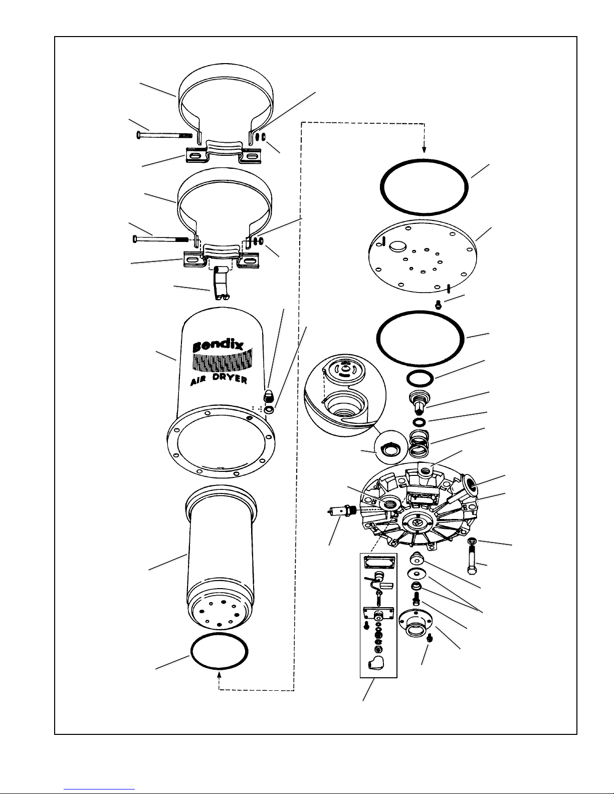
FIGURE 6 - AD-4™AIR DRYER ASSEMBLY
AIR DRYER
HOUSING
THERMOSTAT
ASSEMBLY
SAFETY
VALVE
CHECK VALVE
ASSEMBLY
SCREW
EXHAUST COVER
1/2” CAP SCREW
PURGE VALVE
(8) CAP SCREW 3/8”
SEALING RING
SEALING PLATE
(4) DESICCANT CARTRIDGE
CAP SCREW
& LOCKWASHER
SEALING RING
SEALING RING
END COVER
HEATER
VOLTAGE
SHOWN
SUPPLY PORT
CONTROL
PORT
SPRING
O-RING
PURGE PISTON
SPECIAL
WASHER
EXHAUST
DIAPHRAGM
DELIVERY
PORT
BRACKET
MOUNTING STRAP
CAP SCREW
5/16” X 4-1/2”
BRACKET
MOUNTING STRAP
CAP SCREW
5/16” X 4-1/2”
LOCKWASHER
NUT
LOCKWASHER
NUT
MOUNTING BRACKET HOOK (8) LOCK NUT
(8) SPECIAL
WASHER
DESICCANT
CARTRIDGE
SEALING RING
8
3. Do not attempt to install, remove, disassemble or
assemble a component until you have read and
thoroughly understand the recommended
procedures. Useonly theproper toolsand observe
all precautions pertaining to use of those tools.
4. If the work is being performed on the vehicle’s air
brake system, or any auxiliary pressurized air
systems,makecertain to draintheair pressure from
all reservoirs before beginning ANY work on the
vehicle. If the vehicle is equipped with an AD-IS™
air dryer system or a dryer reservoir module, be
sure to drain the purge reservoir.
5. Following the vehicle manufacturer’s
recommendedprocedures, deactivate theelectrical
system in a manner that safely removes all
electrical power from the vehicle.
6. Never exceed manufacturer’s recommended
pressures.
7. Never connect or disconnect a hose or line
containing pressure; it may whip. Never remove a
component or plug unless you are certain all
system pressure has been depleted.
8. Use only genuine Bendix®replacement parts,
components and kits. Replacement hardware,
tubing, hose, fittings, etc. must be of equivalent
size, type and strength as original equipment and
be designed specifically for such applications and
systems.
9. Components with stripped threads or damaged
parts should be replaced rather than repaired. Do
not attempt repairs requiring machining or welding
unless specifically stated and approved by the
vehicle and component manufacturer.
10. Prior to returning the vehicle to service, make
certainallcomponentsandsystemsarerestoredto
their proper operating condition.
11. Forvehicles with AntilockTraction Control (ATC),
the ATC function must be disabled (ATC indicator
lampshouldbeON)priortoperforminganyvehicle
maintenance where one or more wheels on a
drive axle are lifted off the ground and moving.
AD-4™AIR DRYER REMOVAL
1. Parkthevehicleonalevelsurfaceandpreventmovement
by means other than the brakes.
2. Drain all reservoirs to 0 p.s.i. (0 kPa).— Caution:
Compressor discharge line may still contain residual
pressure.
3. Identify and disconnect the three air lines from the end
coverand notethe positionofendcoverportsrelativeto
thevehicle.
4. Pullboot fromthe thermostatandheatercoverand slide
it onto the wire to expose the connection. Remove nut
and disconnect electrical wire from the terminal. Note:
Vehicleswithinsulatedground (2wire) systemwill have
two boots and two terminals to be disconnected. (See
Figures 5 & 8.)
5. Loosen the 5/16" X 4-1/2" hex bolt securing the upper
and lower mounting straps. Disengage the mounting
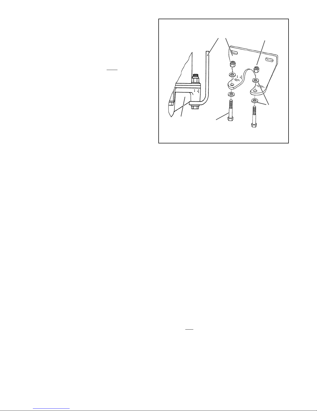
END
COVER
SPECIAL
WASHER
LOCK NUT
LOWER RIGHT ANGLE
BRACKET
EXTRA
LONG
CAP SCREW
bracket hook from the end cover (Refer to Figure 6.)
Note: If theAD-4™air dryer being serviced has a right
angle bracket instead of a lower mounting strap and
safety hook, proceed to step 6, otherwise proceed to
step 7.
6. Remove, retain and mark the two 3/8" end cover cap
screws, lock nuts and four special washers that retain
thelower mounting bracket to theend cover, also mark
thesetwoholes oftheend cover.(Theseboltsarelonger
than the other 6 bolts.)
7. RemovetheAD-4™airdryer fromitsmounting brackets
onthe vehicle.
DISASSEMBLY
The following disassembly and assembly procedure is
presented for reference purposes and presupposes that a
major rebuild of the AD-4™air dryer is being undertaken.
Severalreplacementpartsandmaintenancekitsareavailable
which do not require full disassembly. The instructions
providedwith thesepartsand kitsshould befollowedin lieu
ofthe instructions presented here.Refer to Figure 6during
disassembly.
Caution: While performing service on the AD-4™air
dryer, it is not recommended that a clamping device
(vise, C-clamp, etc.) be used to hold any die cast
aluminum component as damage may result. To hold
the end cover, install a pipe nipple in the supply port
and clamp the nipple into a vise.
1. Remove the remaining 3/8" lock nuts, special washers
and cap screws from the flange of the air dryer and
separatethe endcover fromthe airdryer outerhousing.
Separatethe desiccantcartridge andsealingplate from
FIGURE 7 - LOWER BRACKET INSTALLATION

9
the end cover. Remove and discard the three sealing
rings. One sealing ring is located in the groove on the
sealingplate andthe othertwo arein groovesin theend
cover.
2. Remove 1/4" cap screw from the bottom of the purge
valve and remove the diaphragm washer, exhaust
diaphragm and purge valve. Discard the exhaust
diaphragmandpurgevalve.Removepurgepiston.Note:
Holdpistondownwhenremovingcapscrewduetospring
tension.
3. Remove and discard the check valve assembly in the
recessat the delivery port ofthe end cover.
4. Removethesafetyvalvefromtheend cover(onlyifithas
beendeterminedthatitneedsreplacementduringservice
checks).
5. To removethe thermostatseethe appropriatesection in
thismanual (only ifithas been determinedthat it needs
replacementduring servicechecks).
6. Removepurge pistonand springfromthetopside ofthe
cover.
7. Remove o-ring from the purge piston and discard the
o-ring.
8. Removethe four 1/4"capscrews and lockwashersthat
secure the sealing plate to the desiccant cartridge.
Separatethe sealing plate fromthe desiccantcartridge
anddiscard thesealingring atthe baseofthe cartridge.
CLEANING & INSPECTION
1. Usingmineral spiritsor anequivalent solvent,clean and
thoroughly dry all metal parts.
2. Inspect the interior and exterior of all metal parts that
will be reused for severe corrosion, pitting and cracks.
Superficialcorrosionandorpittingontheexteriorportion
ofthe upper and lowerbody halves is acceptable.
3. Inspectthe boresofboththeend coverfor deepscuffing
orgouges.
4. Makecertain thatall purgevalve housingand endcover
passagesare open andfreeof obstructions.
5. Inspectthe pipe threads intheend cover. Make certain
theyare clean and freeofthread sealant.
6. Inspect the purge valve housing bore and seat for
excessivewear andscuffing.
7. Inspectthe purge valvepiston seat forexcessive wear.
8. Inspect all air line fittings for corrosion. Clean all old
threadsealant from thepipethreads.
9. All o-rings removed should be discarded and replaced
withnew o-ringsprovidedin appropriatekit(s).
Any component exhibiting a condition described in step 1
to 8 should be replaced.
ASSEMBLY
Priortoassembly,coatall o-rings,o-ringgrooves, andbores
witha generous amount ofbarium base lubricant.
Important Note: The single exception to prelubrication
is the sealing ring between the desiccant cartridge and
sealing plate. Refer to step number 8 for proper
installation of this sealing ring. Refer to Figure 6 during
assembly unless otherwise advised.
1. Placereturn springinto cavityin thecenter oftopside of
endcover.
2. Install the purge piston o-ring on the purge piston and
placethe purge piston inside thereturn spring installed
in Step 2.
3. Turnend coveroveron aflat cleansurface(making sure
purgepistonandreturnspringremaininproper position.)
Compressthereturnspringby pushingdownontheend
coverandalign squareshankofpurgepistonintomating
holein the endcover.
4. Placethediaphragmwasher,diaphragm,andpurgevalve
onto the 1/4" cap screw.
5. Install the 1/4" cap screw with parts on it into exhaust
coverand torque to60-80 inch pounds.
6. Install safety valve (if removed) and torque to 120-400
inch pounds, making sure that the exhaust hole is
pointeddownward when thedryeris installed.
7. Install thermostat (if removed). Refer to instructions
pertaining to thermostat installation under section
ThermostatAssembly.
8. Placesealing ringon bottomof desiccantcartridge. The
desiccantcartridge,sealingring andsealingplateshould
be wiped and free of lubricant prior to this assembly
procedure.Attachcartridgeto plate(smoothside ofplate
oppositecartridge)withfour1/4"socketheadcapscrews
andlockwashers.Torqueto 80-100inchpounds.
9. Install the two sealing rings in the recesses of the end
cover.
10. Install the check valve assembly into the end cover
making sure the tang on the check valve assembly fits
into the mating recess in the end cover.
11. Place desiccant cartridge and sealing plate assembly
ontoendcover.(Takingcarenottodisplacesealingrings.)
Thelargehole in the sealingplatemust line up withthe
check valve and spiral pins in the sealing plate must
entercorresponding holesinthe end cover.
12.Installthe outer sealing ring onthesealing plate. Place
theouter housingover thedesiccantcartridge (liningup
marksmadeontheouterhousingand endcover priorto
disassembly) and retain with eight 3/8" hex head bolts,
special washers, and lock nuts. Refer to Figure 8 for
torquepattern.Torque to270-385 inch pounds.Note:If

10
3/8" bolts require replacement, insure that the
replacement bolts are grade 5 minimum and the same
length as the original bolts. Use of inferior bolts can
compromise the integrity of the air dryer and lead to
prematurefailure.Where a lower,rightangle mounting
bracket(instead of alower mounting strap)is used; line
upthemarksmadeontheouterhousingand endcover.
Installthe six (standard) 3/8"cap screws, locknuts and
twelvespecial washers.The twolonger3/8"cap screws
will be used to secure the AD-4™air dryer to the right
anglemounting bracket.
Note: If during the Operation & Leakage Tests it was
determinedthatthethermostatwasinoperative,usethe
following procedure for repair or replacement. It is not
necessary to replace this unit each time the end cover
is rebuilt. Use thermostat maintenance kit 102657 for
singleterminalapplication. Fordualterminal application,
usekit#103982.(See Figure 5.)
THERMOSTAT DISASSEMBLY (Refer to Figures 5
and 8)
1. Remove nut (2), then lockwasher (3), plain washer (4),
nut (2) and o-rings (5). Discard o-ring and retain other
parts.
2. Remove and retain four Phillips head screws (7) and
cover(6).
3. Removeand discardgasket (10).
4. Removeand retainspacer(11).
5. Cutuninsulated thermostatwireat PointB, remove and
discardthermostatand terminal assembly (1).
6. Cleanremaining wire attachedto heater terminal.
7. Cleanthermostat “pocket” inendcover (9).
THERMOSTAT ASSEMBLY (Refer to Figure 5)
1. Cut uninsulated lead of new thermostat (1) at PointA.
2. Install thermostat in end cover pocket and position
uninsulated leads next to each other.
3. Usinga soldering heatsink,clamp uninsulatedleadsat
PointB and solder leadswithstraight rosin core solder.
Do not use acid core solder as corrosion can result.
Cleanexcess solder offend cover.
4. Installthermostat terminal (1) incover (6).
5. Install o-ring (5), washer (4), and nut (2).Torque nut to
20-30inch pounds. Then installlockwasher (3) and nut
(2)finger tightto allowfor reconnectionofelectricalwire
whenreinstalled onvehicle.
6. Installspacer(11) over thermostat(1).
7. Install gasket (7) and thermostat cover (6) and secure
thermostatcoverto end cover (9) usingscrews(7) and
lockwashers(8).
8. Torque to 20-30inch pounds.
9. Test thermostat as follows:
A. At a temperature above 90 degrees Fahrenheit,
check resistance between thermostat terminal (1)
andendcover(9). Resistanceshouldbe1,000ohms
or greater; if not, check for solder “path” short.
B. Chill entire end cover assembly to 40 degrees
Fahrenheit or below and check resistance again.
Resistanceshould be2-4 ohmsfor a12 volt,60 watt
end cover and 4-7 ohms for a 24 volt, 120 watt end
cover.
FIGURE 9 - AD-4™AIR DRYER INSTALLATION SCHEMATIC
COMPRESSOR
UNLOADER
“UNL”
PORT
AD-4™
AIR
DRYER
SUP
SUPPLY
RESERVOIR
8-10 AMP FUSE
TO IGNITION
RESERVOIR
“RES”
PORT
DEL
CON
GOVERNOR
1&9
7
5
6
DELIVERY
PORT
MOUNTING
BRACKET HOOK
SAFETY
VALVE
2
CONTROL
PORT
HEATER
VOLTS/WATTS
EMBOSSED
HERE
8
3
SUPPLY
PORT
4
FIGURE 8 - AD-4™AIR DRYER END COVER WITH TORQUE
PATTERN

11
Bendix parts outlet or sales representative for additional
information.
1. ChargeCycleTime-TheAD-4™airdryeris designedto
provide clean, dry air for the brake system. When a
vehicle’s air system is used to operate non-brake air
accessories it is necessary to determine that during
normal,daily operation the compressorshouldrecover
fromgovernor “cut-in”to governor“cut-out” (usually100
psi to 120 psi) in 90 seconds or less at engine RPMs
commensuratewith thevehicle vocation.If therecovery
time consistently exceeds this limit, it may be
necessaryto “bypass”theair accessoryresponsible for
thehigh airusage. Consultyour localauthorized Bendix
parts outlet or sales representative for additional
information.
2. PurgeCycleTime -During normalvehicleoperation, the
aircompressormustremain unloaded fora minimum
of 20 seconds for the standard AD-4™air dryer or 30
seconds for the extended purge model. These
minimum purge times are required to ensure complete
regenerationof thedesiccantmaterial. Ifthe purge time
is occasionally shorter than the times specified, no
permanentill effectshould beexpected,however, ifthe
purge time is consistently less than the minimum, an
accessory by-pass system must be installed.
3. European Air Brake Systems - Brake systems that
incorporate compressors without integral unloading
mechanismsand/or utilizeacompressor dischargeline
unloadervalve have specialAD-4™air dryer installation
requirements.ConsultyourlocalauthorizedBendixparts
outletor salesrepresentativefor additionalinformation.
4. AirCompressor Size -AlthoughtheAD-4™air dryer can
be used in conjunction with larger compressors, it was
designedprimarilyfor units rated forupto 17 CFM. Itis
recommendedthat when usingtheAD-4™air dryer with
acompressorwhichhasarateddisplacementexceeding
17CFMthatanauthorized Bendixparts outletorBendix
marketingrepresentative be contactedfor assistance.
5. Holset“E orQE”TypeAir Compressors- Inorder forthe
AD-4™airdryerto function properly wheninstalled with
the Holset Type “E or QE” compressor, several
specialized Holset components are required. Consult
your local authorized Holset parts outlet or sales
representativeforadditional information.
6. Use of Standard or Extended PurgeAD-4™Air Dryer -
Usethe followingguidelines:
Total Vehicle Reservoir
Volume Requirement
Less than 9,000 cu. in. ...................StandardAD-4™Air Dryer
9,000-12,500 cu.in. ............................Extended PurgeAD-4™
Air Dryer
Greater than 12,500 cu. in. .............Contact Bendix Rep. or
Bendix Engineering
RE-INSTALLATION
1. Install the assembled AD-4™air dryer (if an AD-4™air
dryerwith alowerright angle bracketinsteadof a lower
mountingstrap isbeing serviced proceedto step#2) on
the vehicle by sliding it into mounting brackets until
mountingbrackethookcatchesunderthelipofthecover.
Proceed to step #3.
2. Install the assembled AD-4™air dryer back onto the
vehicle by slipping it into the upper mounting bracket.
Align the two unused holes in the end cover with the
bottom mounting bracket such that the bottom bracket
supportsairdryer.TheAD-4™airdryer endcovershould
rest on the bracket. Using the remaining two 3/8" cap
screws,four special washers,and two locknuts,secure
the air dryer to the lower bracket. Tighten, then torque
the two remaining cap screws to 270-385 in. Ibs.
3. Tighten the 5/16" x 4-1/2" bolt and nut on the upper
mountingbracket. Torque to 80-120in Ibs.
4. Reconnect the three airlines to the proper ports on the
endcover (identifiedduring disassembly).
5. Reconnect the thermostat and heater wire and place
boot in position to protect connection by forcing it over
knobon plastic cover.
6. Before placing vehicle back into service, perform the
Operation and Leakage Tests stated elsewhere in this
manual.
RETROFITTING THE AD-4™AIR DRYER
GENERAL
Thefollowingretrofitinstructionsarepresentedfor reference
purposes only since Bendix aftermarket retrofit and
replacement air dryers are packaged with the most up-to-
dateinstallationinstructions. Theinstructionspackagedwith
the AD-4™air dryer should be followed in lieu of those
presentedhere.
Thepreceding portionof this manualdeals with“in-service”
repairand orreplacementof theAD-4™airdryer.Theportion
of the manual that follows is concerned with installing an
AD-4™air dryer on a vehicle not previously equipped with
one.
VEHICLE APPLICATION REQUIREMENTS
Thebasic applicationrequirementspresentedhereapplyto
a standard air dryer installation. The majority of highway
vehicles in use today will meet these basic requirements
however,some maynot. Examplesofvehiclesthatmay not
meet the requirements include bulk trailer unloading
operationsand other highair consumption/continuous flow
systems. While the AD-4™air dryer can be used on these
vehicles the standard installation procedure presented in
this manual may require modification to assure proper
operation and service life. Consult your local authorized

12
VEHICLE PREPARATION
1. Parkthevehicleonalevelsurfaceandpreventmovement
by means other than the brakes.
2. Drain all reservoirs to 0 p.s.i. (0 kPa).
LOCATING AD-4™AIR DRYER ON VEHICLE
1. TheAD-4™air dryer must be mounted vertically (purge
exhaust toward road surface) outside the engine
compartmentin anarea of airflow whilethe vehicleisin
motion. The AD-4™air dryer must not be exposed to
direct wheel splash (located behind axle mud flap is
acceptable).
2. Locate theAD-4™air dryer as close to the first (supply)
reservoiras possible.
3. Do not locate the AD-4™air dryer near heat producing
components such as the vehicle exhaust and make
certain adequate clearance from moving components
(e.g. drive shaft, suspension, pitman arm, etc.) is
provided.
4. LocatetheAD-4™airdryeron vehicleso thata minimum
of 11 inches (28 cm) clearance below the end cover is
availabletoallow servicing.Alternatively,provideaccess
to the bracket bolts so the unit may be removed for
servicing.
5. Whenchoosing the mounting locationfortheAD-4™air
dryer,notethedischargelinelength requirementsstated
underthe heading ConnectingtheAir Lines, elsewhere
in this instruction sheet.
ImportantNote: Under normaloperatingconditions,the
maximuminlet airtemperature for theAD-4™airdryeris
160degreesFahrenheit.
MOUNTING THE AD-4™AIR DRYER
1. Assemble the mountingstrap and mountingbracket as
illustrated in Figures5 & 6using the 5/16"screws, nuts
and lock washers. Make certain the mounting bracket
hookisinstalledonthe5/16"screwofthelowermounting
bracketandthatitengagestheAD-4™airdryerendcover.
Makecertain thattheinside surfaceof thetop mounting
strapbearsentirely onthecylindrical surfaceofthe dryer
shell and that it does not overlap the domed top. The
bracketsshouldbe a minimumof 5.5inches apart.After
positioning the mounting straps according to the
installationrequirements, torqueboth 5/16" screws to
80-120inch pounds.
Note:Themountingbracket atthe baseof theAD-4™air
dryercanbeoftwo types.The onedescribed aboveora
singlepieceright anglebracket.(See Figure7.)Toinstall
the single piece lower mounting bracket, remove and
discard two of the bolts and nuts that retain the end
cover. Install the lower mounting bracket as shown in
Figure 7. Utilizing the bolts and lock nuts provided with
thebracket and placingthe washersremovedin proper
sequence,torqueto 270-330inch pounds.To determine
which end cover bolts to utilize to attach the bracket,
takeinto consideration the pipingconnections required
toinstall theAD-4™airdryer and usethose that willbest
position the unit for ease of installation.
2. Auniversal mountingplate (Pc.No.248478)isavailable
tofacilitatethe mounting of theAD-4™air dryer. It is not
includedinkitsbutcanbeobtainedthroughanauthorized
Bendix parts outlet.
3. Use3/8"bolts(grade5min.)andwashers(notfurnished)
tomount theAD-4™airdryertothevehicle.Torque to25
ft.Ibs.(300inch pounds).
CONNECTING THE AIR LINES
PURGE CONTROL LINE
1. Install a purge control air line having a minimum inside
diameter of 3/16 inches between the AD-4™air dryer
end cover control port and an unused unloader port on
thegovernor.The controlline mustbe plumbeddirectto
thegovernorandnotinserieswithautomaticdrainvalves,
lubrication systems, etc.
2. Thecontrol lineshouldslope downwardtotheendcover
withoutforming potential watertraps.
DISCHARGE LINE
General:
Refer to Appendix A, TableA for recommended discharge
line lengths and sizes for various vehicle applications and
vocations.
PURGE EXHAUST LINE
1. If it is necessary to direct AD-4™air dryer discharge
contaminantsaway fromvehicle componentsa 1.5inch
(38.1 mm) I.D. hose can be clamped on theAD-4™air
dryerexhaust cover.
WIRING THE HEATER/THERMOSTAT
1. Notethe required voltageandwattage fortheAD-4™air
dryer heater by checking the end cover as shown in
Figure8.
2. Remove the rubber boot covering the single electrical
terminalofthestandardAD-4™airdryerendcover.Install
a16 gaugewire betweenthe “on”position ofthevehicle
ignitionor engine“kill” switch andthe heater/thermostat
electrical terminal.An 8-10 amp fuse is required in this
lineregardless ofvoltage.

13
3. ForAD-4™airdryerendcoverswith adual terminal(See
Figure 6) heater connections, the power and insulated
return wires may be connected to either terminal. An
8-10amp fuse shouldbe installed inthe power carrying
wire.Use 16 gaugewire for bothpower and return.
4. Allelectrical connections must bewaterproofed.
5. Tie wrap or support all electrical wire leading to the
AD-4™airdryerat6-8inchintervals.Note:Wiresshould
have sufficient slack and not be completely taught.
TESTING THE AD-4™AIR DRYER
Beforeplacing the vehicle in service,performthe following
tests:
1. Closeall reservoir drain cocks.
2. Build up system pressure to governor cut-out and note
that theAD-4™air dryer purges with an audible escape
ofair.
3. “Fan”the service brakes toreduce system air pressure
togovernorcut-in.Notethatthesystemonceagainbuilds
to full pressure and is followed by a purge at theAD-4™
airdryer exhaust.
4. Itis recommended thatthe following itemsbe tested for
leakageto assure that theAD-4™airdryer will not cycle
excessively.
(A) Total air system leakage (See Bendix publication
BW-5057“Air BrakeHandbook”).
(B) Compressorunloadermechanism.
(C) Governor.
(D) Draincockandsafetyvalveinfirst(supply)reservoir.
(E) All air connections leading to and from the first
(supply)reservoir.

14
SYMPTOMS
1. Dryer is constantly
“cycling”or purging.
Dryerpurges frequently
(every 4 minutes or less
whilevehicleisidling).
A. If leakage IS SHOWN on gauges test for
excessiveservicebrake system leakage.
Allowableleakage:
Singlevehicle-1 psi/minute either service
reservoir.
Tractortrailer-3 psi/minute either service
reservoir.Repair andretest as required.
A. Excessive system
leakage.
IMPORTANT:Note whether
air pressure loss is shown
ondashgauge(s). Pressure
loss shown on gauges is
causedbyservice brake
system or component
leakage.PressurelossNOT
SHOWN on gauges is
caused by supply system or
componentleakage.
CAUSE REMEDY
B. If leakage is NOT SHOWN on gauges test for
excessive supply system leakage.
Removedrain cock orvalve in supplyreservoir(wet
tank) and install air gauge. Build system pressure,
allowairdryer to purge and observeairgauge in
supplyreservoir.Pressuredrop should not exceed 1
psi per minute. Perform tests 1 to 6 in the order
presented.
AD-4™AIR DRYER TROUBLESHOOTING CHART

15
1. Test fittings, hoses, lines and connections.
Apply soap solution to detect excessive
leakage.Tightenor replace as needed then
repeattheair dryer charge-purge cycle and
observethegaugeinstalled in the supply
reservoir. Ifleakage is within limitsremove gauge
fromreservoir and replacedrain cock orvalve. If
excessive leakage is detected, continue testing.
2. Test accessories connected tosupplyreservoir.
Drain all air pressure from system, disconnect
all air lines leading to accessories (fan clutch,
wipers, air seats, etc.) and plug the reservoir at
disconnection point. Build air system pressure
untilairdryer purges and observe supply
reservoirgauge. If leakage isnolonger
excessive,repairor replace leaking accessory. If
excessive leakage is detected, continue testing.
3. Test governor leakage. Buildsystempressureto
governorcut-out, turn off engineand apply soap
solutionto governor exhaust portandaround
cap. Leakage should not exceed a 1" bubble in
5 seconds. Reduce system pressure to 80 psi
or less, and re-apply soap solution. Leakage
should not exceed a 1" bubble in 5 seconds. If
excessive leakage is detected in either test,
repairorreplace governor.
4. Test compressor unloaderleakage.Drain all air
pressurefrom system andremove the governor
fromthecompressor.Temporarily plug the
governorunloaderport or air line thatmated with,
or connected to, the compressor. Build air
system pressure until air dryer purges then
IMMEDIATELYSHUTOFFTHE ENGINE.
Observethe air gauge inthesupply reservoir. If
leakage is within limits, replace the compressor
unloaders.Re-connect the governor tothe
compressor(after removing plug installedin
governor)and retestwhileobserving supply
reservoirgauge. If excessive leakageis
detected, continue testing.
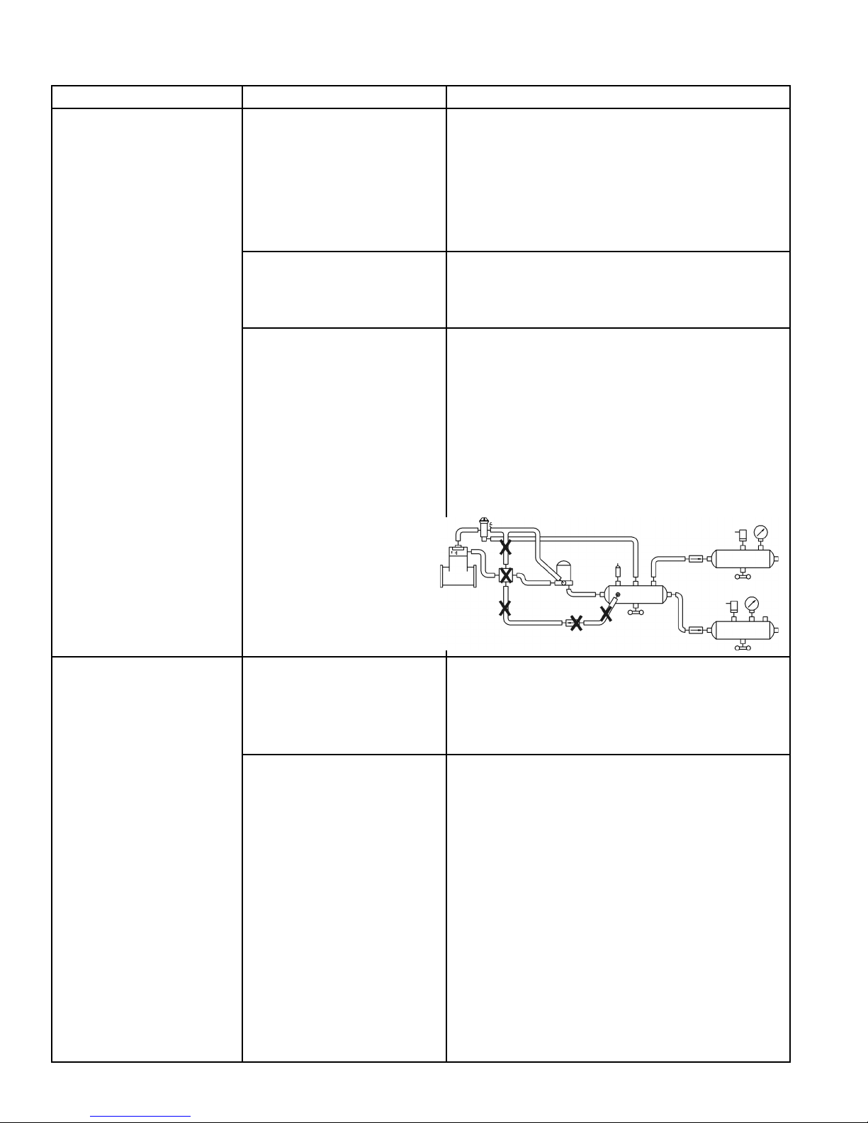
5. Test airdryer purge valveand outlet (delivery)
checkvalve.Drainallair pressure from system,
remove the control line connection at the air
dryer and plug the end of the air line leading to
thegovernor(not the air dryer control port). Build
systempressure to governor cut-outandobserve
airgauge.If little or no pressure drop is observed
replacetheair dryer check valve. Ifpressure
drop continues apply soap solution to air dryer
purgeexhaustand purge control port (wherethe
controllinewas removed). Leakage shouldnot
exceed a 1" bubble in 5 seconds. If leakage is
excessiverepair orreplace purgevalve
assembly.
REMEDY
CAUSE
SYMPTOMS
AD-4™AIR DRYER TROUBLESHOOTING CHART (Continued)
16
AD-4™AIR DRYER TROUBLESHOOTING CHART (Continued)
SYMPTOMS CAUSE REMEDY
6. Withgauge installed atRESportof governor,
pressureshould not dropbelow”Cut-In” pressure
attheonsetof the compressor “Unloaded”
cycle. If pressure drops, check for “kinks” or
restrictions in line connected to RES port. Line
connected to RES port on governor must be
samediameter,orpreferably larger than, lines
connectedto UNLport(s)on governor.
B. Remove end cover.Apply120psi at control port.
Soapbothsides around purge valve to testfor
control piston leakage. Leakage should not
exceed a 1" bubble in less than 5 seconds.
C. Test the Holset E Compressor unloader system
withfeedback line and checkvalve for proper
operation. Make certain Holset ECON is not
usedwiththedrop-in version of the air dryer, if
so,removeand retest.
B. Leakingpurge valvein air
dryerend cover(control
side).
C. Holset “E” type
compressor.
When installing a Bendix Drop-In air dryer in a
system equipped with a Holset E or QE
compressor,remove theHolsetECON valvealong
withitsfeedback and governor control line.
2. Water and/or Oil in
Supplyor Service
Reservoir.
A. Improperdischarge line
lengthor improper line
material.Maximumair
dryerinlettemperatureis
exceeded.
B. Air system charged from
outsideairsource
(outsideairnotpassing
throughair dryer).
A. Refer to section entitled Connecting the Air Lines
as well asAppendixA, Table A columns 1 & 2
then and check line size and length.
B. If system must have outside air fill provision,
outside air should pass through air dryer. This
practice should be minimized.

17
AD-4™AIR DRYER TROUBLESHOOTING CHART (Continued)
SYMPTOMS
2. Water and/or Oil in
Supplyor Service
Reservoir(continued).
CAUSE REMEDY
E. Excessive air usage,
duty cycle too high - Air
dryernotcompatible
with vehicle air system
requirement(Improper air
dryer/vehicle
application).
NOTE: Duty Cycle is the
ratio of time the compressor
spends building air to total
enginerunningtime.Air
compressorsare designed
tobuildair (run “loaded”) up
to 25% of the time. Higher
duty cycles cause
conditions that affect air
brakechargingsystem
performancewhich may
requireadditional
maintenance. Factors that
add to the duty cycle are: air
suspension,additionalair
accessories, use of an
undersizedcompressor,
frequentstops,excessive
leakagefrom fittings,
connections, lines,
chambersor valves, etc.
D. Check causes and remedies for Symptom #1.
E. SeeAppendixA, TableA, column 1, for
recommendedcompressorsizes. If the
compressoris“too small” for the vehicle vocation
(forexample, where a vehicle’svocationhas
changedorservice conditions exceed the original
vehicleorengine OE spec’s) then upgrade the
compressor. Note: The costs incurred (e.g.
installing a larger capacity compressor, etc.) are
notcovered under originalcompressor warranty.
Charge Cycle Time -TheAD-4™air dryer is
designedtoprovide clean, dry air for the brake
system. When a vehicle’s air system is used to
operate non-brake air accessories it is necessary
todeterminethat; during normal, daily operation
thecompressor shouldrecover fromgovernor
“cut-in”togovernor “cut-out” (usually 100 psi to
120 psi) in 90 seconds or less at engine RPM’s
commensuratewiththe vehicle vocation. If the
recovery time consistently exceeds this limit, it
may be necessary to “bypass” the air accessory
responsible for the high air usage.An example of
where a by-pass system would be required is
when the compressor is used to pressurize a
tanktrailer for purposes ofoff-loading product.
Consult your local authorized Bendix parts outlet
orsales representative foradditional information.
PurgeCycle Time - Duringnormal vehicle
operation, the air compressor must remain
unloaded for a minimum of 30 seconds. This
minimum purge time is required to ensure
completeregenerationof the desiccant material.
If the purge time is consistently less than the
minimum, an accessory by-pass system must be
installed. Consult your local authorized Bendix
partsoutletor sales representative foradditional
information.
Air Compressor Size -Although theAD-4™air
dryer can be used in conjunction with larger
compressors, it was designed primarily for units
rated for up to 30 CFM. It is recommended that
when using theAD-4™air dryer with a
compressor which has a rated displacement
exceeding 30 CFM that an authorized Bendix
partsoutletor Bendix marketing representative
be contacted for assistance.
D. Purge (air exhaust) time
insufficientdueto
excessive system
leakage(seecauses for
Symptom #1).
C. See Symptom #5.C. Airdryer not purging
(see Symptom #5).

18
AD-4™AIR DRYER TROUBLESHOOTING CHART (Continued)
SYMPTOMS
2. Water and/or Oil in
Supplyor Service
Reservoir(continued).
DischargeLineFreeze-UpThedischargelinemust
maintainaconstantslopedownfromthe
compressortothe air dryer inletfittingto avoid low
pointswhere ice may form and block the flow. If,
instead, ice blockages occur at the air dryer inlet,
insulation may be added here, or if the inlet fitting is
a typical 90 degree fitting, it may be changed to a
straightor45degreefitting.Formore informationon
howtohelppreventdischargelinefreeze-ups,see
BendixBulletinsTCH-08-21andTCH-08-22.Shorter
dischargelinelengthsorinsulationmaybe required
in cold climates.
Insufficientcoolant flowthroughcompressor.
Inspect coolant line. Replace as necessary (I.D.
is 1/2" min.). Inspect the coolant lines for kinks
and restrictions and fittings for restrictions.
Replace as necessary. Verify coolant lines go
from engine block to compressor and back to the
waterpump.Repairasnecessary.
Restricted air inlet (not enough air to
compressor). Check compressor air inletline for
restrictions, brittleness, soft or sagging hose
conditions etc. Repair as necessary. Inlet line
size is 3/4 ID. Maximum restriction requirement
for compressors is 25 inches of water. Check the
engineairfilterand service if necessary (if
possible, check the air filter usage indicator).
Poorly filtered inlet air (poor air quality to
compressor).Checkfor leaking, damaged or
malfunctioningcompressorair inlet components
(e.g. induction line, fittings, gaskets, filter bodies,
etc.). Repair inlet components as needed. Note:
Dirt ingestion will damage compressor and is not
coveredunderwarranty.
Ifyoufoundexcessive oil present in the service
reservoirandyou did not find any issues above,
the compressor may be passing oil.
Replacecompressor.Ifstill under warranty, follow
normalwarranty process.
G. Ifyoufoundexcessive oil present in the service
reservoirandyou did not find any issues above,
the compressor may be passing oil. Test the
compressor using the BASIC cup method as
describedintheBendix compressor service
manual and referred to inAppendixA,TableA,
column 5.
Replacecompressor.Ifstill under warranty, follow
normalwarranty process.
CAUSE REMEDY
G. Compressormalfunction.
F. Restricted discharge line. SeeAppendixA,
TableA, column 1 & 2 for recommended sizes.
If discharge line is restricted or more than 1/16"
carbonbuildupis found, replace the discharge
line. Replace as necessary.
F. Air compressor
dischargeand/or air
dryerinlet temperature
too high.

19
I. Desiccantrequires
replacement.
AD-4™AIR DRYER TROUBLESHOOTING CHART (Continued)
SYMPTOMS CAUSE REMEDY
H. If vehicle uses Holset compressor, inspect
feedbackcheck valve forproperinstallation and
operation.
When replacing the desiccant cartridge, make
sure desiccant cartridge assembly is properly
installed and sealing rings are in place on
mountingsurfaceof desiccant cartridge.
H. Air by-passes desiccant
cartridgeassembly.
I. Replace desiccant cartridge assembly. Refer to
AppendixA, TableAcolumns 3 & 4 for
recommendedintervals.
A. Air dryers remove water and oil from the air
brake charging system.Asmall amount of oil is
normal. Check that regular maintenance is
being performed and that the amount of oil in the
air tanks (reservoirs) is within the acceptable
range shown on the BASIC cup (see also
column 5 ofAppendixA, TableA). Replace the
airdryercartridge as needed and return the
vehicleto service.
A. Airbrake charging
system is functioning
normally.
3. Oil present at air dryer
purgeexhaust or
cartridgeduring
maintenance.
A. Check to determine if air is reaching supply
reservoir. Inspect for kinked tubing orhose.
Checkforundrilledor restricted hose or tubing
fittingsandrepairor replace as needed.
B. Verify relief pressure is at vehicle orcomponent
manufacturerspecifications. Replace if
malfunctioning.
C. Refer toAppendixATableAand column 3.
Check compressor for excessive oil passing
and/orcorrectcompressor installation. Repair or
replace as necessary. Replace desiccant
cartridge.
D. Test to determine if air is passing through check
valve.Repair orreplace.
E. Increasevolume in discharge linebyincreasing
length or diameter.Add a ping tank (small
reservoir).
A. Restrictionbetween air
dryerandsupply (first)
reservoir.
B. Airdryer safetyvalve
malfunction.
C. Desiccantcartridge
maintenancerequired.
D. Malfunctioningdischarge
checkvalve inend cover
of theAD-4™air dryer.
E. Excessivepressure
pulsationsfrom
compressor. (Typical
single cylinder type).
4. Safetyvalve on airdryer
“poppingoff”or
exhaustingair.

20
AD-4™AIR DRYER TROUBLESHOOTING CHART (Continued)
D. Excessivebends in
dischargeline(water
collectsandfreezes).
E. RefertoSymptom4,
causes E & F.
SYMPTOMS CAUSE REMEDY
F. Governormalfunction.
Missing or restricted
governorcontrolline
installation.
F. Testgovernor operation and/orinspectthe
controlline leading fromthegovernor UNL
(unloader)porttotheair dryer control port.
5. Constantexhaust of air
atair dryerpurge valve
exhaust.(Charge
mode.)
A. Airdryerpurgevalve
leakingexcessively.
B. Compressorfails to
unload(stop
compressingair) and air
dryerpurge exhaust
makes“sputtering”or
“popping”sound.
C. Purge control line
connectedto reservoir or
exhaustport ofgovernor.
D. Purgevalvefrozen open-
malfunctioningheater
andthermostat,wiring,
blownfuse.
A. With compressor loaded, apply soap solution
onpurgevalve exhaust, to test for excessive
leakage.Repairpurgevalve as necessary.
B. Confirm failure to unload by increasing &
decreasingengineRPM and noting change in
the rate of leakage and intensity of
accompanyingleakage sound. Repair/replace
compressorunloaders.
C. Purge control line must be connected to
unloaderportofgovernor.
D. Test heater and thermostat as described in
PreventativeMaintenance Section.
E. See Symptom #1.
E. Excessive system
leakage.
F. Purgevalve stays open-
supply air leaks to
control side.
F. Repair purgevalve andhousing.
6. Can not build system air
pressure. A. Inlet and outlet air
connectionsreversed.
B. Checkvalvebetweenair
dryerand first reservoir.
C. Kinkedorblocked
(plugged)dischargeline.
A. Connect compressor discharge to air dryer
supplyport.Reconnectlines properly.
B. Test checkvalvefor proper operation.Repair or
replace as necessary.
C. Check to determine if air passes through
discharge line. Check for kinks, bends,
excessive carbon deposits, or ice blockage.
D. Discharge line should be constantly sloping from
compressor to air dryer with as few bends as
possible.
E. Refer to Symptom #4, Remedies E & F.
7. Airdryer does not purge
or exhaust air. A. Missing, broken, kinked,
frozen,plugged or
disconnectedpurge
control line.
A. Inspectcontrol linefrom governorUNL(unloader)
port to control port of air dryer. Test to determine
airflowsthrough purge control line when
compressorunloaded. Check for undrilled
fittings. (See Symptom #4, Remedy C.)
B. Afterdetermining airreaches purge valve
(RemedyAabove),repairpurgevalve.
C. Refer to Remedies B, E, G for Symptom #4.
B. Faultyair dryer purge
valve.
C. See Causes, B, E, G for
Symptom #4.
This manual suits for next models
1
Table of contents
Other BENDIX Dryer manuals


Popular Dryer manuals by other brands


Bosch
Bosch WTG8620XCL Installation and operating instructions

Beko
Beko DPS7405 XW3 user manual

Kenmore
Kenmore 796.8077 series Use & care guide and installation instructions

Amana
Amana NDE8805AZW Use & care guide

Oliver
Oliver DVX Operation manual

American Dryer Corp.
American Dryer Corp. AD-75 parts manual


