2
DISASSEMBLY
AIRHORN
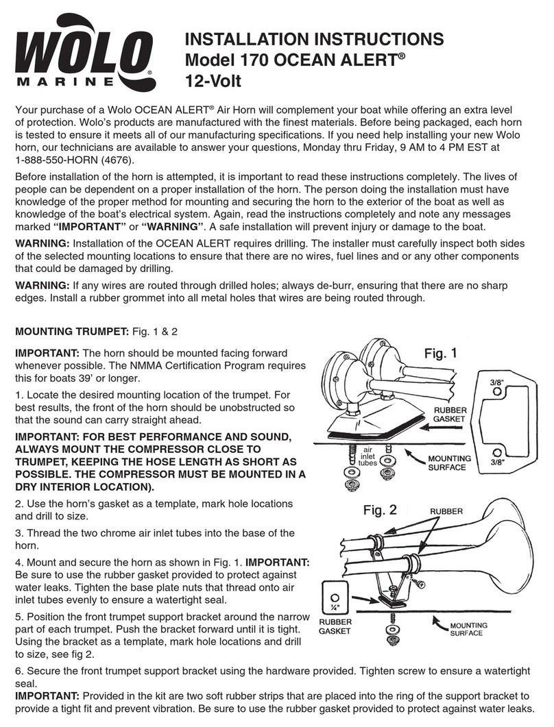
1. Removetheeightnutsandboltsholdingthetwocovers
to the body.
2. Removethediaphragmsfromthebody of the air horn.
3. Remove the spring contact, springs, and spring
assembliesfromthe covers of air horn.
4. Removethehornbellsfrom the body.
HORNVALVE
1. Removethe spring cage from the valvebody.
2. Removethevalve stemfromthevalve body.
3. Removethestrainerandspring from the spring cage.
CLEANING AND INSPECTION
AIR HORN
1. Wash all metal parts in cleaning solvent.
2. Carefullyinspect the diaphragmstobesure they arenot
cracked, deteriorated, or distorted in any way. If ridges
orcracksare found, the diaphragms mustbe replaced.
3. Inspect condition of the body. Be sure diaphragm seat
in body is not chipped or damaged in any way. Check
forcracksinthebody.Iftheseconditionsprevail,replace
body.
4. Inspectcondition of the covers. Besurediaphragmseat
in cover is not chipped or damaged. Inspect the cover
forcracks.Ifthese conditions prevail, replace covers.
5. Inspect the horn bells. If they are cracked or broken,
theyshouldbe replaced.
6. Inspectthespring contacts. If distorted ordeteriorated,
theyshouldbe replaced.
7. Checkthespring. If broken, replace.
HORN VALVE
1. Inspectsupplyvalveand seat. If damaged, they should
berepaired or replaced.
2. Checkthespring. If broken, replace.
3. Be sure the valve stem does not bind when inserted in
thevalvebody.
ASSEMBLY
NOTE: When using pipe thread sealant during assembly
andinstallation, take particular care topreventthe
sealant from entering the valve itself. Apply the
sealantbeginningwiththe secondthreadback from
theend.
AIRHORN
1. Place the diaphragms in the body.
2. Install the spring contacts, springs, and spring
assemblies to the covers.
3. Install the eight bolts and nuts, attaching cover to the
body.Care should be usedtobesureequal pressure is
exertedonall the screws holding thecover to the body.
4. Assemble the horn bells to the body.
HORNVALVE
1. Insertthevalvesteminthevalvebody.
2. Place the strainer and spring in the spring cage.
3. Assemble the spring cage to the body.
TEST OF REBUILT AIR HORN AND HORN VALVE
Both operating test and leakage test must be made after
rebuildingorrepairinganairhornorhornvalve.Iftheairhorn
doesnot operatesatisfactorily,adjustmentofthe springload
behindthe diaphragm can be madebyturningtheadjusting
screw in the cover. Before attempting to turn the adjusting
screw,loosentheadjustingscrewlocknut.Besure totighten
the adjusting screw lock nut after any adjustment.
WARNING! PLEASE READ AND FOLLOW
THESE INSTRUCTIONS TO AVOID
PERSONAL INJURYOR DEATH:
When working on or around a vehicle, the following
general precautions should be observed at all times.
1. Park the vehicle on a level surface, apply the
parking brakes, and always block the wheels.
Always wear safety glasses.
2. Stop the engine and remove ignition key when
working under or around the vehicle. When
working in the engine compartment, the engine
should be shut off and the ignition key should be
removed. Where circumstances require that the
enginebe in operation, EXTREME CAUTION should
be used to prevent personal injury resulting from
contact with moving, rotating, leaking, heated or
electrically charged components.
3. Do not attempt to install, remove, disassemble or
assemble a component until you have read and
thoroughly understand the recommended
procedures. Useonly the proper tools andobserve
all precautions pertaining to use of those tools.
4. If the work is being performed on the vehicle’s air
brake system, or any auxiliary pressurized air
systems,make certainto drainthe airpressure from
all reservoirs before beginning ANY work on the
vehicle. If the vehicle is equipped with an AD-IS™
air dryer system or a dryer reservoir module, be
sure to drain the purge reservoir.
5. Following the vehicle manufacturer’s
recommendedprocedures, deactivate theelectrical
system in a manner that safely removes all
electrical power from the vehicle.
6. Never exceed manufacturer’s recommended
pressures.
7. Never connect or disconnect a hose or line
containing pressure; it may whip. Never remove a
component or plug unless you are certain all
system pressure has been depleted.
8. Use only genuine Bendix®replacement parts,
components and kits. Replacement hardware,
tubing, hose, fittings, etc. must be of equivalent
size, type and strength as original equipment and
be designed specifically for such applications and
systems.
9. Components with stripped threads or damaged
parts should be replaced rather than repaired. Do
not attempt repairs requiring machining or welding
unless specifically stated and approved by the
vehicle and component manufacturer.
10. Prior to returning the vehicle to service, make
certain all components and systems are restored
to their proper operating condition.
BW1592 © 2004 Bendix Commercial Vehicle Systems LLC All rights reserved. 4/2004 Printed in U.S.A.
