BERMAN gemini Tinytag Plus User manual

Tinytag Plus LAN Single Input Voltage Data Logger
TE-4704
Issue 1 (16th June 2017) E&OE
BERMAN Termómetros e Instrumentación S.L.
ventas@e-berman.info
Telf. 93 263 24 50
www.e-berman.info
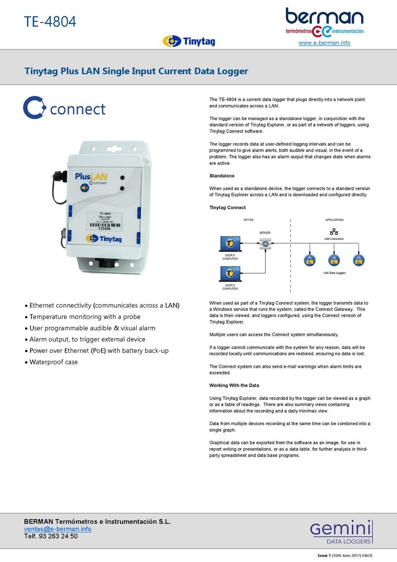
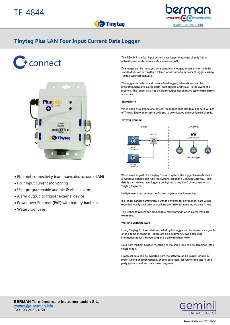
The TE-4704 is a voltage data logger that plugs directly into a network point
and communicates across a LAN.
The logger can be managed as a standalone logger, in conjunction with the
standard version of Tinytag Explorer, or as part of a network of loggers, using
Tinytag Connect software.
The logger records data at user-defined logging intervals and can be
programmed to give alarm alerts, both audible and visual, in the event of a
problem. The logger also has an alarm output that changes state when alarms
are active.
Standalone
When used as a standalone device, the logger connects to a standard version
of Tinytag Explorer across a LAN and is downloaded and configured directly.
Tinytag Connect
When used as part of a Tinytag Connect system, the logger transmits data to
a Windows service that runs the system, called the Connect Gateway. This
data is then viewed, and loggers configured, using the Connect version of
Tinytag Explorer.
Multiple users can access the Connect system simultaneously.
If a logger cannot communicate with the system for any reason, data will be
recorded locally until communications are restored, ensuring no data is lost.
The Connect system can also send e-mail warnings when alarm limits are
exceeded.
Working With the Data
Using Tinytag Explorer, data recorded by the logger can be viewed as a graph
or as a table of readings. There are also summary views containing
information about the recording and a daily min/max view.
Data from multiple devices recording at the same time can be combined into a
single graph.
Graphical data can be exported from the software as an image, for use in
report writing or presentations, or as a data table, for further analysis in third-
party spreadsheet and data base programs.
· Ethernet connectivity (communicates across a LAN)
· Voltage monitoring
· User programmable audible & visual alarm
· Alarm output, to trigger external device
· Power over Ethernet (PoE) with battery back-up
· Waterproof case
connect

Tinytag Plus LAN Single Input Voltage Data Logger
TE-4704
Issue 1 (16th June 2017) E&OE
BERMAN Termómetros e Instrumentación S.L.
ventas@e-berman.info
Telf. 93 263 24 50
www.e-berman.info
Reading Specification
Physical Specification
The logger can be wall mounted or placed
on its back on a flat surface, such as a
shelf.
The logger's back-plate has mounting
holes, as shown.
IP Rating IP67*
*Applies only if the supplied waterproof shroud for the Ethernet connection is
fitted.
This data logger is for indoor use only. The waterproofing provided by
the connector shroud is to protect against ingress in indoor applications
when condensation or liquids may be present.
Operational Range** -20°C to +55°C
Case Dimensions
Length/Height 161mm / 6.34"
Width 113mm / 4.45"
Depth 62mm / 2.44"
Weight 394g / 13.9oz
**The Operational Range indicates the physical limits to which the unit can be
exposed.
Mounting Instructions
Warnings
· This logger should only be connected to the inputs specified above,
otherwise damage to the logger may occur.
· Do not connect to voltages greater than 25V
relative to earth or isolated supplies larger
than 25V.
Temperature
Reading Range 0 to 25V DC
Logger Accuracy ±0.2% of reading ±0.02V
Logger Resolution Better than 1mV
Maximum Input 26V
Input Impedance 1MΩ
This data logger will turn on and start recording as soon as it is plugged into a
Power over Ethernet (PoE) supply (it can also be turned on before that by
pressing and holding the logger's Mute button briefly) .
Logging Interval 2 minutes to 10 days
Default Logging Interval 10 minutes
Logging/Off-line Capacity 361 days typical, at a 10 minute
logging interval
The logging/off-line capacity for a data logger, for any given logging interval, is
stated at the bottom of the configuration page in Tinytag Explorer when the
logger is programmed.
Standalone Mode
If being used as a standalone device, the logger should be launched using
Tinytag Explorer to ensure its clock is set correctly.
Data Logging

Tinytag Plus LAN Single Input Voltage Data Logger
TE-4704
Issue 1 (16th June 2017) E&OE
BERMAN Termómetros e Instrumentación S.L.
ventas@e-berman.info
Telf. 93 263 24 50
www.e-berman.info
Connections
This logger can be used with a CAB-3239 Tinytag Voltage/XP Input Lead
(supplied) or an ACS-9703 5-Pin Plug.
The connection details for the cable and plug are as follows:
CAB-3239 5-Pin Plug Function
Red A Not Connected
Green B Not Connected
White C Sense Line
Black D Common/0V
Yellow E Signal Input
The Sense line is a signal line that changes state when a reading is taken.
The line goes from 0v to +3.3V whilst a reading is being taken (the line goes
back to 0V when the reading cycle is complete).
The line has an impedance of 100K.
The Sense line does not need to be connected for the data logger to record
correctly.
Alarms
LAN data loggers can be programmed with alarm limits to warn when a
property has gone out of specification.
Alarms 2 fully programmable, latching alarms
Alarm Delay 1 second to 10 days
Alarm Indicators Visual (LED) & audible (sounder)
Alarm Output 3-pin, powered output that changes state
when alarms are active (see below)
Tinytag Connect
When used as part of a Tinytag Connect system, an on-screen alarm
indication is also shown in the Tinytag Explorer Connect software.
E-mail warnings can be sent from the Tinytag Connect system when alarm
limits are breached, and these in turn can be used to send SMS messages
using third-party messaging services.
External Alarm Output
Warnings
· The alarm cable and connector must not be connected to any voltage
more than 50V away from earth potential, including mains voltages
· Maximum current through any connection: 200mA
· Maximum voltage on the Signal output (relative to Ground): 30V
The alarm output has a signal line that changes state when alarms are active
and it can also supply power to an external device.
Connection Information
An output cable (part number CAB-0041, supplied separately) is used to
connect the logger to an external device.
The wiring connections are as follows:
Both the Power (brown) and Signal (white) outputs are protected by a 350mA
self-resetting fuse.
Signal Specification
This is an open-drain output that is pulled to Ground when an alarm is active
(otherwise it is open-circuit). This output will continue to change state, in the
event of an alarm, should the PoE supply to the logger fail.
Note that muting the internal alarm sounder, by pressing the mute button
on the front of the logger, will also turn off the output. If required, the
connection should be held on (latched) by external equipment until it is
explicitly acknowledged.
Power Specification
The power output is regulated at 11·5V ±0.5V from the PoE supply. The output
voltage will therefore turn off if the PoE supply fails.
Colour Connection
Brown Power
Green Ground
White Signal

Tinytag Plus LAN Single Input Voltage Data Logger
TE-4704
Issue 1 (16th June 2017) E&OE
BERMAN Termómetros e Instrumentación S.L.
ventas@e-berman.info
Telf. 93 263 24 50
www.e-berman.info
Required Parts
Two Ethernet cables (not supplied) are required to connect this receiver
to a LAN.
This logger is a PoE device and is supplied with a PoE injector as standard. If
the logger is being used on a powered network, or a number of loggers are
being connected to a powered hub, this product can be supplied without the
injector.
When used as a standalone device, a copy of the following software is
required:
SWCD-0040 Tinytag Explorer
When used as part of a Tinytag Connect system, a copy of the following
software is required:
SWCD-0080 Tinytag Explorer Connect
Connections
You will also require one of the following:
CAB-3239 Tinytag Voltage Input Lead (supplied) or an
ACS-9703 5-Pin Plug
Further Related Products
ACS-0040 RJ45 waterproof (IP67) Shroud (supplied)
ACS-0041 PoE Injector (supplied)
CAB-0041 Plus LAN alarm output lead
Required and Related Products
Power Information
This logger is a PoE (Power over Ethernet) device that is powered from its
Ethernet connection (a PoE injector is supplied).
In the event of a failure of the PoE supply, the logger has a battery back-up
that will keep it recording (communications will be suspended until power is
restored).
Back-up Battery Power
Battery Type 2 x Duracell Industrial ID1500
AA (LR6) 1.5V (supplied)
The logger will operate with other AA cell batteries but performance cannot be
guaranteed.
When the logger’s back-up batteries start to run flat, the LED on the front of
the logger will flash red. If being used as part of a Tinytag Connect system, a
low battery warning will be displayed in the Tinytag Explorer Connect software.
The low battery warnings will start to show when the logger has approximately
two weeks of battery power remaining.
Before replacing batteries the logger must be disconnected from the LAN and
turned off.
Alkaline batteries should always be replaced in pairs.
Data stored in the logger will be retained after its batteries are replaced.
Warranty
This logger is configured to meet Gemini’s quoted accuracy specification
during its manufacture.
We recommend that the calibration of this unit should be checked annually
against a calibrated reference meter.
A traceable certificate of calibration can be supplied for an additional charge
either at the point of purchase, or if the unit is returned for a Service
Calibration.
Calibration
This product carries a manufacturing defects warranty of 12 months from the
date of purchase. Units returned under warranty will be repaired or replaced at
the manufacturer’s discretion. This warranty does not cover mishandling,
modification or battery replacement and is subject to our standard Terms and
Conditions of Sale, a copy of which can be found at www.tinytag.info.
Action LED Status/Operation
n/a No Indicators Device is powered off
n/a Red flash every 4
seconds
The device is powered on and
has a problem.
Either:
a) Battery is low or
b) An alarm indicator is
signalled.
Check the nature of the
problem using Tinytag
Explorer.
n/a Green flash every 4
seconds
The device is powered on, and
does not have any problems.
Press and briefly
hold the mute
switch.
Green indicator
shows for one
second. It then
briefly flashes green
then red.
The device has been switched
on.
Press and hold the
mute switch for 3
seconds.
Red indicator shows
for one second.
The device has been switched
off.
n/a Yellow indicator on
constantly
The device is being powered
from its Ethernet connection,
but no communications have
been established.
n/a Blue (flickering) Ethernet communications are
established and on-going
Ethernet Radio Receivers and LAN data loggers have two status LEDs; one to
show the status of the logger’s Ethernet connection (yellow/blue) and the
second to show the status of the unit (green/red).
Note that the yellow and blue LEDs cannot be on at the same time. If the
blue LED is on (or flickering) then PoE power must be available.
LED Flash Patterns
Approvals
Gemini Data Loggers (UK) Limited hereby declares that this data logger is in
compliance with the essential requirements and other relevant provisions of
EMC directive 2014/30/EU and RoHS directive 2011/65/EU. A copy of the
declaration of conformity is available upon request.
This logger also conforms to the following EMC standards EN 61326-1:2013,
FCC/CFR 47:Part 15:2016 & Canadian Standard ICES-003:Issue 6.
This logger also complies with (RJ45) 10/100Mb Base-T for Ethernet
connectivity and PoE standard IEEE 802.3af.
Gemini Data Loggers (UK) Ltd. operates a Business Management System
which conforms to ISO 9001 and ISO 14001.
This manual suits for next models
1
Other BERMAN Data Logger manuals
Popular Data Logger manuals by other brands
CARLO GAVAZZI
CARLO GAVAZZI Eos-Gate Installation and operation manual
Hi-Target
Hi-Target HTS-420R Maintenance manual

Lascar Electronics
Lascar Electronics EL-EnviroPad-TC quick start guide
LogTag
LogTag TRED30-16R manual
Symmetricom
Symmetricom ATS-6501 Tflex user guide
RKI Instruments
RKI Instruments EAGLE 2 Operator's manual
