Beta Max SCAFF-TRAC 60-4 Series User manual

BETA MAX PORTABLE HOIST SYSTEMS 1
ContentsContents
ContentsContents
Contents
WARRANTY ....................................................................... 2
INTRODUCTION ................................................................ 3
ELECTRICAL BASICS ......................................................... 4
OTHER IMPORTANT INFORMATION .................................. 5
BETA MAX MOUNTING OPTIONS ....................................... 5
SCAFF-TRAC HOIST MOUNTING SYSTEM ........................... 6
SCAFF-TRAC & SCAFF-TRAC EXTENSION ASSEMBLY AND
MOUNTING ....................................................................... 7
MAC-TRAC HOIST MOUNTING SYSTEM ..............................
MAC-TRAC ASSEMBLY AND MOUNTING ........................... 11
TRESTLE MONORAIL ....................................................... 12
TRESTLE MONORAIL ASSEMBLY ...................................... 14
TRESTLE MONORAIL ANCHORING METHODS .................. 15
MOUNTING THE HOIST ON A MONORAIL/TRAC SYSTEM . 16
VERTICAL POST MOUNTING SYSTEMS ............................ 18
HOIST OPERATION ......................................................... 20
WIRE ROPE SPECIFICATIONS ......................................... 23
SAFETY RULES CHECKLIST.............................................. 28
HOIST ELECTICAL SPECIFICATIONS ............................... 2
CONICAL BRAKE ............................................................. 30
CONICAL BRAKE PARTS LIST .......................................... 32
TRANSMISSION / DRUM ASSEMBLY ............................... 33
MOTOR / BRAKE ASSEMBLY ............................................ 34
TECHNICAL SPECIFICATIONS ......................................... 36
TROUBLE SHOOTING ...................................................... 38

2 BETA MAX PORTABLE HOIST SYSTEMS
WARRANTY
Beta Max Inc. warrants its equipment to be free from defects in material and under normal use
and service.
Our obligation under this warranty as outlined below is limited to repairing or replacing at our
discretion any part of the unit which proves upon examination to be defective in material or
workmanship. The item is to be returned to Beta Max Inc. through an authorized distributor. The
warranty period as below is from the date that the equipment is sold to the original purchaser*.
Return shipments must be prepaid.
High Wear Items:
Wire rope pulleys hooks shackles ................................. 30 days or 1 month
Electrical:
Pendant switches electrical plugs and cable...................... 90 days or 3 months
Mechanical:
Motor brake wire rope drum trolley wheels ..................... 1 year
Gears:
Gear reduction drive assembly ........................................ 5 years
Any parts proven to be defective upon inspection will be repaired or replaced at no cost for the
parts. The obligation under this warranty includes labor and freight costs if determined the prod-
uct failed under normal usage within the above described time.
Any defect in this equipment must immediately be brought to the attention of the distributor from
whom the unit was purchased. The distributor will make arrangements with the factory for repairs
or replacement of parts with the terms of this warranty. Distributors must get a return authoriza-
tion number from Beta Max before any item is returned for repair or replacement.
Beta Max Inc.s’ obligation is limited to replacing parts and does not include replacing the com-
plete unit. This warranty is void on any unit that has been modified or tampered with repaired by
persons other than a factory representive or an authorized Beta Max distributor repaired with
other than Beta Max standard parts or damaged by reasons of accident alteration misuse or
abuse.
This warranty is in lieu of all other warranties expressed or implied. We do not authorize any
person or representative to make other guarantee or to assume for us any liability in connection
with the sale of our products other than those contained herein. Any agreement outside of or
contradictory to the foregoing shall be void and of no effect.
* “Original Purchaser” definition: for rental machines: Dealer; for resale machines: First user.

BETA MAX PORTABLE HOIST SYSTEMS 3
INTRODUCTION
The Beta Max electric utility hoists are general purpose hoists designed for the construction indus-
try but suitable for other applications that require a compact lightweight easily handled and
efficient hoisting unit. The hoists can be mounted in a variety of ways to serve various applications.
The hoists are powered by a 110V or 220V AC reversable electric motor. A conical brake system is
incorporated into the design and will hold the maximum load when electric current is broken or
when neither lifting nor lowering is required. The motor is fan cooled and all electrical components
are protected from weather. The gear reduction system is completely enslosed in a die cast alumi-
num housing with a sealed lubrication system. Gears and bearings operate in an oil bath.
There is an emergency UP-Limit switch which stops the hoisting operation when the load has
reached the upper limit of travel. Different models of the hoist have different weight capacities
cable lengths and minor differences in control configurations.
TOOLS REQUIRED TO REPAIR BETA MAX ELECTRICAL HOISTS
Hex Head (Allen) Wrench (long T-handle type) 4mm 5mm and 6mm sizes
Sockets and Wrenches (set of 6 point and 12 point)
10mm 11mm 12mm 17mm 19mm and 22mm Metric sizes
7/16” 7/8” U.S. sizes
Flat point screwdrivers 1/4” and 3/16”
Phillips head screwdrivers #1 and #2
Retaining snap ring (external) pliers
Diagonal cutting pliers
Bearing pullers as needed
Feeler gauge
Wire rope-servicing tools
Nicopress Crimping Tools 1/16” 3/16” and 1/4”
(or equivalent wire rope terminating tools or clamps)
AMP pin and socket removal tools:
9 pin and socket removal tool .................................. #453300-1-0
Brake pin removal tool ........................................... #1-305183-1-b
Brake socket removal tool ....................................... #1-305183-2
Remote cable pin and socket tool ............................. #1-305173-r
Large units may use three-phase power. Standard units are single-phase. Single-phase units are
NOT field changeable between 110V AC and 220V AC.

4 BETA MAX PORTABLE HOIST SYSTEMS
ELECTRICAL BASICS
The electricity that powers your Beta Max hoist is as important as the hoist itself. Electricity is more
than one thing.
CHARGE is a group of particles gathered together. Charge can flow and build up pressure which is
called VOLTAGE. The greater the voltage the more charges flow. The measurement of the charge is
called AMPERAGE. Limiting the flow of charge is RESISTANCE.
Let us compare electricity to water. Everyone can understand — imagine water passing through a
faucet and hose.
• The levels of PRESSURE in the pipe is the equivalent to VOLTAGE.
• The amount of (volume) WATER flowing can be associated with AMPERAGE.
• The FAUCET and the SIZE of hose associated to the power supply and the length and
gauge of electrical cable effecting RESISTANCE.
The voltage at your electrical outlet may be 110 volts or 220 volts with no motor plugged in or
even when a couple of pieces of equipment are plugged in and running but... just like with your
plumbing if there are two people taking a shower a dishwasher machine on the rinse cycle the
lawn sprinklers sprinkling and so on then the PRESSURE will be less for all of the water faucets.
Electrical power in American cities is not always perfect. When a couple of pieces of equipment are
plugged into one circuit and drawing a high AMPERAGE the VOLTAGE will drop. The VOLTAGE
(PRESSURE) will not always remain unchanged it will decrease. How badly it drops depends on
your electric power company specific wiring to that job site and the length and type of extension
power cable (HOSE SIZE) being used.
What about the FAUCET (RESISTANCE)? If your faucet is rusted corroded or small or if the faucet
is a long distance from the source the water PRESSURE is not going to be as strong as you would
like? Likewise with electricity if your electrical connections are not good or the electrical extension
cable is too lightweight or the length of your electrical cable excessive or any combination of these
circumstances then the VOLTAGE at the hoist may be too little to lift your load.
Beta Max electrical hoists are high energy hoists and can lift large loads at high speeds but this
requires a lot of AMPERAGE (WATER VOLUME) and therefore a lot of continuous VOLTAGE (PRES-
SURE). The greater the load the more AMPERAGE necessary. Beta Max hoists require more AM-
PERAGE than a simple rotary saw or drill. 20 to 30 amperes on 110 volt units and 10 to 20 am-
peres on 220 volt units.
Beta Max hoists are supplied with “Twist Lock” plugs because they are safer more efficient conduc-
tors of your electrical current. Beta Max Hoists also come with 30 amp service because of the
higher energy (amperage) requirements of the hoists. Beta Max suggests no less than 10 gauge
(10/3 S.O.) for 110 volt machines and 12 gauge (12/3) for 220 volt machines. Heavier electrical
cable is required for Beta Max hoists and will allow a longer distance between the power source and
the hoist without causing an excessive resistance to the current flow.
To help remember the basics of electrical motor needs remember:
• Water Pressure = Voltage Level
• Pipe Diameter = Wire Gauge
• Faucet Opening = Connector Capacity
• Water Volume = Current Draw (amperes)

BETA MAX PORTABLE HOIST SYSTEMS 5
OTHER IMPORTANT INFORMATION
What is strain relief? A strain relief on an electrical cable does just what it says it will relieve the
strain or pull on the electrical cable when the cable is hanging from a height.
What is the difference between 110 volts and 220 volts of power? This may seem like a dumb
question but the complete answer is not always understood. A 110 volt electrical motor will not
run on a 220 volt circuit and visa versa. This is true of all Beta Max hoists. 220 volt electrical
motors have the advantage over 110 volt units because they allow for the use of longer extension
cords (less resistance). 220 volts also require less AMPERAGE to run and therefore are able to run
cooler and longer than 110 volt units.
Beta Max requires a 50% duty cycle for Electrical Hoists. The hoist should be resting 30 minutes in
every hour.
BETA MAX MOUNTING OPTIONS
Mounting load* capacities are not the same as lifting capacity. Know the lifting capacity of your
hoist. Know the load capacity of your mounting device.
Make sure that the mounting devices are secured correctly at the work site before attempting to
attach the hoist. Secure the hoist properly to the mounting device. Inspect the entire installation
each day to assure all nuts bolts and other fittings are secure.

6 BETA MAX PORTABLE HOIST SYSTEMS
SCAFF-TRAC HOIST MOUNTING SYSTEM
TECHNICAL SPECIFICATIONS
The Scaff-Trac monorail system is designed for most models of Beta Max hoists. The system is
made for the suspension under standard 6 ft. walk-thru tubular scaffold frames with a 7 ft. center
spacing. The basic section allows for a 3.5 ft. cantilever at the outward end of the scaffold run. A
load may be raised up on the cantilevered end and then rolled horizontally in between the scaffold
frames.
The basic section is 11 ft. long and includes 2 mounting saddles and 4 mounting pins. Optional
Scaff-Trac extension section are 7 ft. long and include 1 mounting saddle and 2 mounting pins.
Extensions are butted up to the inboard end of the basic section and fitted into guide pins (see
diagram pg. 7). Additional extension sections can be added as needed.
The mounting saddles and brackets allow mounting on various brands of scaffolds. The spacing
between the top and bottom horizontal ledgers (variable X in the diagram pg. 7) of 6 ft. walk-thru
scaffolding depends on the brand of scaffolding. The Monorail/Trac MUST ALWAYS be mounted snug
against the bottom ledger of the scaffolding. The mounting saddles and brackets are designed with
multiple hole configurations to allow for a wide range of variable X.
SCAFF-TRAC MODELS
*Adaptable to trestle monorail system
Scaffold frames should always be securely pinned together anchored to building face and counter-
balanced appropriately. Check Scaffolding Industry Association guidelines.

BETA MAX PORTABLE HOIST SYSTEMS 7
SCAFF-TRAC & SCAFF-TRAC EXTENSION ASSEMBLY AND MOUNTING
List of Parts:
2 ea. Saddles
1 ea. Scaff-Trac Monorail/Trac (11 ft. length)
4 ea. Mounting Pins with keys
1 ea. Inboard End Retaining Pin
PREPERATION OF THE MOUNTING SITE
As the name implies the Scaff-Trac hoist mounting option is designed for use on any 6 ft. walk-thru
scaffolding frames. The X-brace spacing between frames must be set at 7 ft. A full width deck must
be installed at the location of the hoist to provide adequate working room and footing for installing
and operating the hoist. The scaffolding must be horizontally level (check the scaffolding manufac-
tures mounting specifications for leveling your scaffolding platform). Guardrails and toe boards may
also be necessary (check local safety requirements to be sure).

8 BETA MAX PORTABLE HOIST SYSTEMS
Scaffolding frames must be in good condition and free of dents bends heavy corrosion cuts
modifications or any other damage. All X-braces must be in place and secured before attempting to
install the Scaff-Trac. Scaffolding frames must be pinned or bolted to the frames below and all
frames must be anchored to the vertical building face. Check with the scaffold manufacturer for the
correct way to erect and anchor your scaffolding. Use no less than two people to install the Mono-
rail/Trac.
The design of the saddles and mounting brackets on the Scaff-Trac are intended to allow mounting
on various brands of scaffolding. The spacing (dimension-X on diagram) between the top and
bottom horizontal ledger on 6 ft. walk-thru frames can and does vary from one brand of scaffolding
to another. The amount of space or play between the top of the Scaff-Trac and the lower horizontal
ledger of the scaffold frame should be as small as possible. The saddles and mounting brackets are
designed with multiple holes to allow mounting to various manufacturers scaffold frames. These
holes allow for minimum top to bottom ledger distance of 5/8” an intermediate distance of 6” and
maximum distance of 6 1/4”.
INSTALLATION OF THE SCAFF-TRAC MONORAIL
1. Place one saddle over the center of each of the scaffolding frames. The holes in the saddles
should line up. There are two sets of holes on each saddle to allow for different manufacturers
scaffolding frames.
2. Raise both ends of the Scaff-Trac Monorail/Trac to the under side of the saddles and insert the
pins into the same set of holes on each saddle. The monorail must be level.
INSTALLATION OF THE SCAFF-TRAC EXTENSION
List of Parts:
2 ea. Saddles
1 ea. Scaff-Trac Monorail/Trac (7 ft. length)
4 ea. Mounting Pins with Keys
1 ea. Inboard End Retaining Pin
1. A Scaff-Trac monorail must first be correctly mounted.
2. Place the saddle over the next scaffolding frame on the inboard side of the mounted Scaff-Trac.
3. Raise the outboard end of the Monorail/Trac extension to the inboard end of the Scaff-Trac and
correctly align it with the ears and alignment tabs. The extension will slide into place.
4. Raise the inboard end of the extension to the saddle and secure it with the pins.
5. Install succeeding extensions in the same manner.

BETA MAX PORTABLE HOIST SYSTEMS 9
MAC-TRAC HOIST MOUNTING SYSTEM
TECHNICAL SPECIFICATIONS
Mac-Trac the Masons and Chimney-builders’ Trac was designed to lift materials to workmen on a
short run of scaffolding while still allowing for a sufficient work area on the platform.
Mac-Trac mounts easily on top of 4 ft. 5 ft. or 6 ft. standard 1 5/8” tube frame scaffolding.
The system is set for 7 ft. X-bracing and the track cantilevers 2 ft. out over the X-brace side of your
scaffolding tower. By removing the X-brace at the level work is performed a load can be pulled in
by hand and set down on the work platform.
For lifting larger loads the system can be adjusted to raise material up through the center of the
scaffolding to the work platform. The hoist and Trac can be cantilevered in the center of the 7 ft.
span or to the left or right of center in optional mounting holes.

10 BETA MAX PORTABLE HOIST SYSTEMS
COMPONENTS
The Mac-Trac system consist of two supports and the Monorail/Trac. Two identical horizontal sup-
ports (30 lbs. each) span the 7 ft. The frame and rest on the scaffold coupling pins. Gravity lock
pins fasten the supports to the coupling pins and J-hooks clamp securely around the top horizontal
ledger of the scaffolding.
The Monorail/Trac is formed channel (45 lbs.) specifically made to accept the roller wheels of the
the Scorpio hoist model. The Trac is slotted at the open end to make it easy to load the hoist.
Mounting stud bolts on the Trac fit into one of three (3) optional mounting locations on the horizon-
tal supports.
FEATURES
• No loose parts.
• No threads to get damaged.
• Can be installed easily by one man.
• Hoist secured by U-clamp at 1 ft. or 2 ft. overhang for varying types of loads.
• Safety pin prevents the hoist from rolling out of the Trac.
Sca olding rames should always be securely pinned together, anchored to the
building ace and counterbalanced appropriately. Check Sca olding Industry
Association guidlines.

BETA MAX PORTABLE HOIST SYSTEMS 11
MAC-TRAC ASSEMBLY AND MOUNTING
List of Parts:
2 ea. 7 ft. horizontal braces
1 ea. 7 ft. Mac-Trac Monorail/Trac
4 ea. 2 in. retaining clips
2 ea. retaining clips
PREPERATION OF THE MOUNTING SITE
Mac-Trac mounting option is designed for use on most scaffold frames. The X-brace spacing be-
tween frames must be set at 7 ft.. A full deck must be installed at the location of the hoist to
provide adequate work room and footing for installing and operating the hoist. The scaffolding must
be level (check the scaffold manufacturers mounting specifications for leveling your scaffolding
platform). Guardrails and toe boards may also be necessary (check local safety requirements to be
sure).
Scaffolding frames must be in good condition and free of dents bends heavy corrosion cuts
modifications or any other damage. All X-braces must be in place and secured before attempting to
install the Mac-Trac. Scaffolding frames must be pinned or bolted to the frames below and all
frames must be anchored to the vertical building face. Check with the scaffold manufacturer for the
correct way to erect and anchor your scaffolding.
INSTALLATION OF THE MAC-TRAC MONORAIL
1. Set the two braces to the top of the scaffold frames as shown in the diagram. Secure to the
scaffolding with the clamp.
2. Slip the monorail into the desired set of mounting holes on the braces as shown in the dia-
gram. Attach the clips to secure the monorail from slipping out.
3. Load the hoist from the open end of the monorail and secure in place with the retaining pins.
12 BETA MAX PORTABLE HOIST SYSTEMS
TRESTLE MONORAIL
The universal mounting option system for all Beta Max portable hoists the Trestle Monorail is ideal
for mounting on a flat roof or an intermediate floor. The system allows a 3.5 ft. cantilever. Two
people can assemble the system in minutes.
TRESTLE MONORAIL ANCHORING METHODS
Trestle Ceiling Brace: For use when the trestle will be installed on an intermediate floor of a build-
ing with a rigid structural ceiling above the trestle. The brace that locks the rear of the trestle
between the ceiling and the floor on which the system is mounted stabilize the trestle monorail.
After the trestle is assembled and placed in the desired location the jack is bolted to the top of the
inboard end of the monorail. The jack must be in firm contact with the ceiling structure.
Floor Tie Down Clamps: Most suitable for permanent applications. The clamps attach to the inboard
legs of the trestle and allow the system to be anchored by chains or wire rope.
Ballasting: A counterbalance system employing two rigid metal containers (each with a capacity of
9.5 cubic ft.) that are bolted to the inboard leg of the trestle. The weight of the material in the
ballast containers counterbalances the combined weight of the load and the hoist at the outboard
end of the trestle. Ballast material must conform to certain requirements. Bricks solid concrete
blocks stone or other high-density non-flowable materials are suggested.
Counterweighting: Uses counterweight clamps which come complete with mounting hardware and
attach securely to the inboard legs of the trestle. This method lets you make use of flat steel coun-
terweights commonly used for roof outriggers. Standard 50 lb. counterweights slide down over the
27 in. upright.
Whatever anchoring method you use additional tie back ropes should always be in place to secure
the system.

BETA MAX PORTABLE HOIST SYSTEMS 13

14 BETA MAX PORTABLE HOIST SYSTEMS
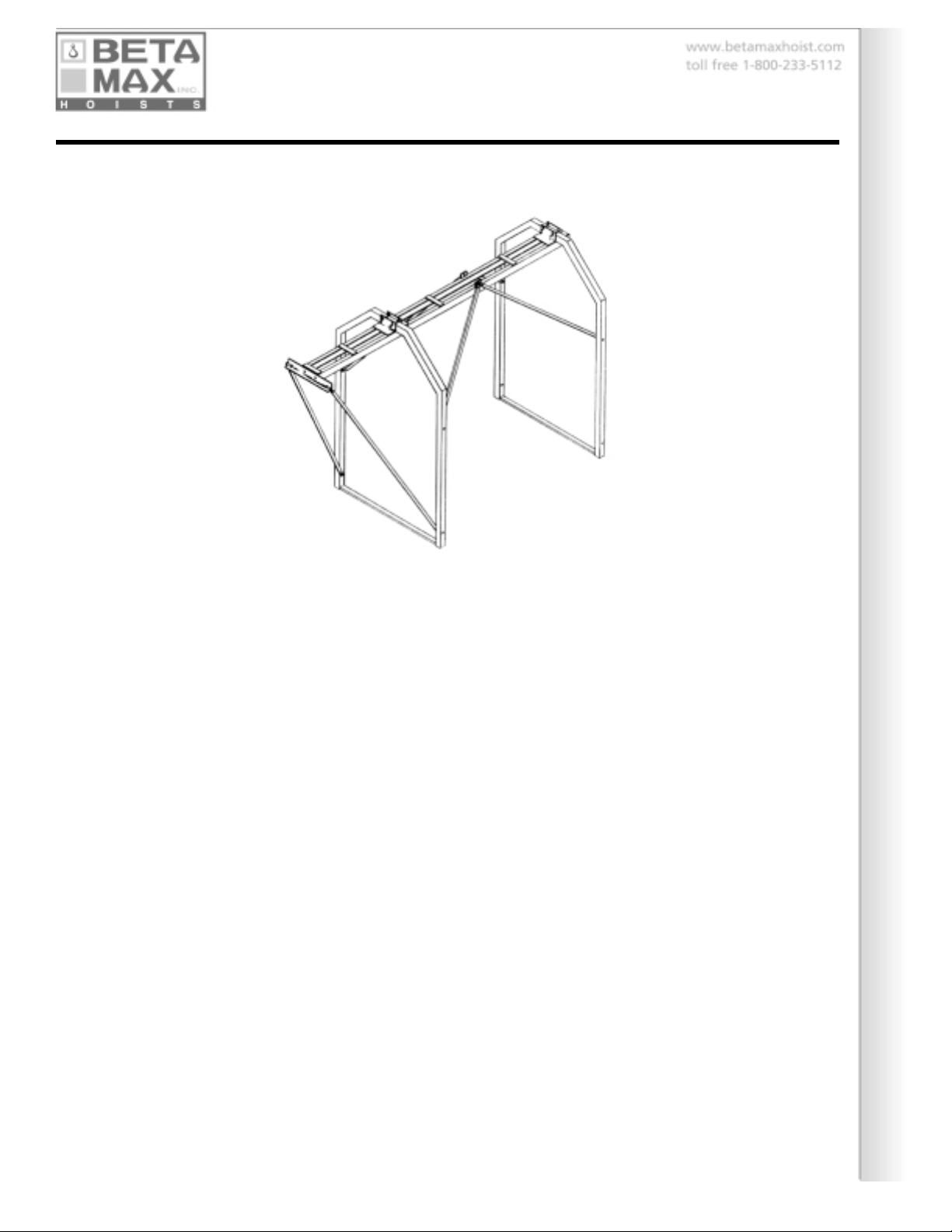
TRESTLE MONORAIL ASSEMBLY
PREPERATION AND ASSEMBLY
The Trestle Monorail system is ideal for mounting Beta Max hoists on a flat roof or intermediate
floors. An area of approximately 10 ft. x 15 ft. is needed to assemble the Trestle Monorail. Beta
Max suggest that two people assemble the system. The system should be assembled at the site of
installation. (It is possible to assemble the system in one area and then move it to the installation
area).
List of parts (1200 lb. capacity trestle monorail): see pg. 13
2 req. Uprights—Trestle monorail
1 req. Scaff-Trac
4 req. Braces—Trestle Monorail (1200 lb. capacity)
2 req. 1/2” bolt 2” long
1 req. Long Pins
ASSEMBLY OF 1200 LB. CAPACITY TRESTLE MONORAIL
1. Attach 4 braces (D) to upright (A) using bolts (F). Tighten loosely.
2. Connect braces (D) in center towards each other using bolt (E). Tighten loosely. This is tempo-
rary. The uprights (A) should be approx. 7 ft. apart.
3. attach Trac (B) to uprights (A) from underneath using pins and keepers (C).
4. Disconnect bolts (E) from braces (D).
5. Connect braces (D) to Trac (B) using bolts (E).
6. Tighten all bolts securely and use the keepers for the pins holding Trac to uprights. Always use
counterbalancing. (see pg. for formula).
List of parts (2000 lb. capacity trestle monorail): see pg. 13
Same as above/also with
2 req. 1/2” bolt 3 1/2” long
1 req. Cantilever Bracket
2 req. 1/2” bolt 1 1/2” long
2 req. Braces—cantilever (2000 lb. capacity)
2 req. 1/2” bolt 3” long
ASSEMBLY OF 2000 LB. CAPACITY TRESTLE MONORAIL
1. Follow above instructions.
2. Attach cantilever brace bracket (G) to Trac (B) using bolts (H).
3. Attach cantilever braces (I) to uprights (A) using bolts (F).
4. Attach cantilever braces (I) to cantilever brace bracket (G) using bolts (I).

BETA MAX PORTABLE HOIST SYSTEMS 15
TRESTLE MONORAIL ANCHORING METHODS
INSTALLING THE TRESTLE MONORAIL
Once the Trestle Monorail is assembled it must then be properly anchored before it can be used
with a Beta Max hoist. Beta Max warranties cover only the following four methods of anchoring.
1. Trestle ceiling brace: When the trestle will be installed on an intermediate floor of a building so
that there is a rigid structural ceiling above the trestle it may be stabilized with a jack which
locks the rear of the trestle between the ceiling and floor on which the trestle is placed. After
the trestle is assembled and placed in the desired location the jack is bolted to the top of the
inboard (rear) end of the monorail. The jack is extended until it is in firm contact with the
ceiling structure.
2. Floor tie down clamps: This method of trestle Monorail installation is the most suitable for
more permanent applications. Anchor bolts must be secured to the floor near the base of the
inboard end of the trestle arch. Beta Max suggests no fewer than two bolts per arch leg and at
a distance of no less than 12 inches from the trestle arch legs. Beta Max floor tie down clamps
are adequate to attach to the trestle arch legs. A heavy chain or equivalent should be used to
connect the floor tie down clamps to the anchor bolts.
3. Ballasting: Two rigid metal containers each with a capacity of 9.5 cubic feet are bolted to the
inboard legs for the trestle. The weight of the material in the ballast containers counterbal-
ances the combined weight of the load and the hoist at the outboard end of the trestle. The
choice of ballast material must conform to certain requirements. Bricks solid concrete blocks
stone or other high-density material is suggested. Loose sand may not be considered suitable
in some installations. Liquids are not approved. To assure maximum stability each box should
be filled to capacity.
4. Counterweighting: 2 u-shaped counterweight clamps are attached securely
to the inboard legs of the trestle. 50 lb. flat steel counterweights slide
down over the 27" upright. (See counterbalance requirements on page 16 & 17.)
The reactive loads on the trestle system and its foundation are shown on page 38. The foundation
under the tresle must be adequate to support the entire load. Load spreading planks must be
placed under the trestle if the combined weight for the ballast payload trestle and hoist exceeds
the unit loading capacity of the floor.
Use tie back cables on all methods of anchoring. Tie back the rear arches of the trestle.

16 BETA MAX PORTABLE HOIST SYSTEMS
MOUNTING THE HOIST ON A MONORAIL/TRAC SYSTEM
Monorail/Trac mounting is only possible with hoist that have rollers attached. See table for further
information about mounting options for your hoist. Beta Max suggests the mounting be done by
two or more people.
1. Remove the retaining pin or bolts from the inboard end of the Monorail/Trac.
2. Raise the hoist and roll it into the Monorail/Trac.
3. Reinstall the retaining pins to prevent the hoist from rolling out of the rear of the Monorail/
Trac.
4. Make sure that the hoist rolls freely over the entire length of the Monorail/Trac. Clean any dirt
rust mortar etc. which may be on the inside of the Monorail/Trac.
5. Be sure that the Monorail/Trac is horizontally level and mounted securely. The hoist should not
roll to one end by itself.
COUNTERBALANCING MONORAIL SYSTEMS
When the load is at the outboard end of the Monorail/Trac the inboard end of the Monorail/Trac will
have a lifting tendancy and must be properly counterbalanced or secured in place. A load sus-
pended at the outboard end of the Monorail/Trac will exert an upward force of approximately one
half its weight on the inboard end of the Monorail/Trac.
Scaffold sections in a Scaff-Trac mounting system must be pinned or bolted together to resist the
weight of the load at the outboard end. In addition extra weight can be added above the rear
(inboard end) scaffold frame. When first lifting the maximum weight the job superintendent should
inspect the scaffolding in the vicinity of the hoist operation to insure that the scaffold components
are NOT distorted or seperated.
HOIST / LOAD COUNTERBALANCE REQUIREMENTS
To determine the proper amount of counterweight to use - see the formula and chart below:
When mounting to Trestle Monorail or Scaff-Trac:
Take weight of hoist plus weight of load. Multiply by length of outward cantilever (Trestle Monorail
Scaff-trac = 3.5 ft.) Multiply by 2x safety factor. Divide by backward cantilever (Trestle/Monorail
Scaff-Trac = 7 ft.).

BETA MAX PORTABLE HOIST SYSTEMS 17
for example:
Gemini Plus lifting 600 lb. load on Scaff-Trac
600 + 150 = 750
750 x 3.5 = 2 625
2 625 x 2 = 5 250
5 250 / 7 = 750 lbs. Total of counterweight
When mounting to vertical post:
Using 1 to 1 safety factor you must provide counterweight equal to weight of hoist and load.
for example:
Scorpio Plus lifting 400 lb. load on vertical post
400 + 100 = 500 total counterweight
ASSEMBLY / INSTALLATION OF BETWEEN FLOOR MOUNT SYSTEM
The floor is used on the edge of balconies or just inside windows and doors where both the upper
and lower end of the mount rests against a flat surface. The small diameter end of the mount is
placed toward the ceiling and the larger diameter tube is set toward the floor. Tighten the system
with the adjustment screw to lock the vertical post between the two surfaces. Make sure the post is
vertical to the floor. Attach the tubular mounting clamps as high as possible on the window mount.
Secure the clamps and the hoist as described above. Connect your hoist to the proper electrical
supply and you are ready to lift.
INSTALLATION OF A SCAFFOLDING MOUNT SYSTEM
Scaffold mounting is simple and quick. The scaffold section that is to be mounted to should be
erected and properly secured to the building face. All sections should be correctly secured to each
other. Diagonal braces for the scaffold sections must also be in place. attach the tubular mounting
bar and hoist as described above to one of the OUTER legs of the scaffolding sections. Connect
your hoist to the proper electrical supply and you are ready to lift.
DO NOT MOUNT HOIST TO FREE STANDING SCAFFOLDING
SCAFFOLDING MUST BE SECURED TO A BUILDING FACE

18 BETA MAX PORTABLE HOIST SYSTEMS
VERTICAL POST MOUNTING SYSTEMS
ASSEMBLY / MOUNTING OF WINDOW MOUNT SYSTEM
The Window Mounting system can be mounted in any masonry framed window.
1. Remove the retaining pin and thread the adjustment screw completely closed. Extend the
assembly to the approximate window opening size. Insert the pin under the adjusting screw. If
the smallest adjustment for the mount exceeds the window dimension then both tubes of the
mount must be cut off a suitable amount. Use a hack saw or pipe cutter to cut the tubes
straight across not at an angle.
2. Place the assembled mount in the window opening with side flanges on the OUTSIDE and
toggles on the inside. The larger diameter tube should be on top.
3. Rotate the adjustment screw until the top and bottom plates are firmly against the window
opening.
4. Insure that side flanges are firmly against outside wall and that the mount is plumb vertical
use a level if necessary. Turn adjustment screw to tighten the mounting securely into place.
5. give adjustment screw a final turn but do not use a leverage bar to over torque.
6. attach the tubular mounting clamps as high as possible on the window mount. Secure the
clamps and hoist as described above. Connect your hoist to the proper electrical supply and
you are ready to lift.
7. Re-tighten all bolts and clamps after the initial load has been placed on the window mount
system.
APPROVED ONLY FOR MASONRY WALLS

BETA MAX PORTABLE HOIST SYSTEMS 19

20 BETA MAX PORTABLE HOIST SYSTEMS
HOIST OPERATION
Electrical power for the hoist must be the correct voltage (see nameplate data). The power source
and connecting cords must be of sufficient capacity to carry the current requirements of the hoist.
A minimum of 20 amp. service is required for all units. Electrical extension cable plug ends should
be “twist lock” type. Connectors must be straight undamaged and clean and should incorporate
suitable ground connections. #10 or #8 guage electrical cable should be used for extensions #6 is
suggested for excessive lengths. Consult your dealer or the Beta Max factory.
CONTINUOUS OPERATION OF A MOTOR WITH BORDER LINE OR POOR VOLTAGE
DUE TO THE POWER SOURCE OR POWER CONNECTIONS CAN DAMAGE YOUR BETA
MAX HOIST MOTOR!
On remote control machines the remote control cable consists of a basic 6 ft. electrical cable and
pendant with the push buttons at one end and quick disconnect plug at the other. Electrical cable
extensions of 25 ft. and 85 ft. can be added to operate the hoist from remote locations. When
using the longer remote control extensions securely attach the cable to firm anchor points to
prevent strain on the connectors or the electrical cable. Intermediate connections should use strain
relief provisions provided to prevent strain on the connectors.
Press the DOWN button to lower the cable and load. The load will be powered down and does not
free fall. Press the UP button to raise the load. Releasing either button will cut power to the motor
and automatically apply the brake. Always control the load motion with the control buttons. DO
NOT run the load into the ground and DO NOT use the UP-Limit switch to stop upward motion.
The wire rope will stretch and tighten when a load is first “snatched”. The tightening of the rope will
cause the load to rotate slightly in one direction. The non-rotational qualities of the rope will stop
this rotation and the rope and load will seek a “balanced” state. The load may also rotate due to air
movement or the bulk and nature of the payload. A tag line may be attached to the load to steady
it but should not be used to pull the load out at an angle away from the hoist.
WIRE ROPE RIGGING
Some hoists are shipped with the components for rigging either for single rope or double rope
lifting. Double rope rigging requires an 8” sheave and pulley another hook and a shackle. The
hoists’ wire rope is terminated with a weight (headache ball) and thimble.
SINGLE ROPE RIGGING
for single part rigging it is only necessary to attach the small hook to the end of the cable using the
shackle. This allows the maximum lifting height and speed for the hoist. (See table pg. 23 for
maximums).
DOUBLE ROPE RIGGING
For two parts rigging secure the wire rope to the side of the hoist with the shackle. Unscrew the
center bolt of the 8” pulley / hook and remove the wheel. Insert the cable (as shown on the dia-
gram pg. 21). Re-secure the pulley wheel and central bolt. Be sure to secure the bolt with the
safety clip provided. This bolt MUST be secured with a safety pin. Double rigging will limit the lifting
height and speed to 1/2 load capacity for your hoist. Be certain your mounting is rated for the
increased weight that double rope rigging will allow.
This manual suits for next models
1
Table of contents
Other Beta Max Construction Equipment manuals


