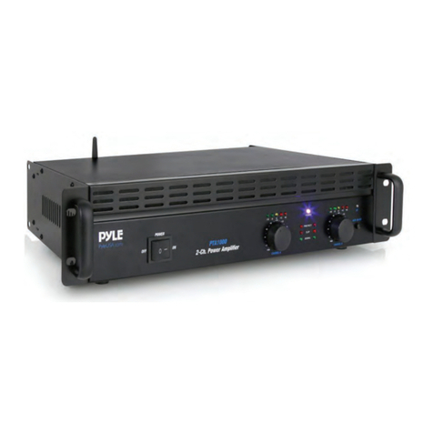
Beta Three BA5120 User manual

PUBLIC ADDRESSAMPLIFIER
BA5240BA5120
ED-B3-MA-090218-001
USER MANUAL
//
3-SMSW-1YSL05

Please read the user manual carefully beforeusing BA series, and operate according
to the user manual strictly. Any questions, please ask for thelocal distributor.
P3
P3
P4
P5
P5
P6
P7
P9
P9
P10
DEAR CUSTOMERS
CONTENTS
1
2
3
4
5
6
7
8
9
10
ATTENTIONS
FUNCTIONS&FEATURES
PARAMETERS
FRONT PANEL
BACK PANEL
POWER SUPPLY
FUNCTION SETUP AND CABLE CONNECTION
OPERATIONS
PROTECTION FUNCTIONS
TROUBLES AND TROUBLE SHOOTINGS
//
P11
11
SAFETY INSTRUCTIONS

1. ATTENTIONS
3
2. FUNCTIONS&FEATURES
.Do not open the cover because existdangerous voltage,please ask theprofessional to repair
Do not expose it to the raining ormoisture.
Do not put it under the direct sunshine, hightemperature or heat source.
Keep good ventilation, not stop the ventilating hole.
Note the local voltage must matched withthe voltage required.
Please put off the plug if not use for a long time.
Connect with right load, not work under overload for a long time.
Do not let the obstacle into the unit,keep the unit away the obstacles.
Please stop using if the cable is damaged.
The equilateral triangle with lightning bolt warnsthe user of dangerous voltage levels
localized within the cabinet.
The equilateral triangle with exclamatory mark meansthe important operation on the
user's manual.
Symbols:
BA is a integrated amplifier with completed functions,can meet the demand of
small public address system separately.
series
1 > Five channels input
INPUT1-INPUT4 can be choosed to be balanced microphone input with low impedance,
built-in 24V eidolon power microphone inputor line balance input with high impedance.
INPUT5 is unbalanced line input with high impedance,INPUT1 is fault channel,can control
other channel output
2 > Balanced rated voltage outputwith 100V 70V, 4 Ohms rated impedance output .
3 > Separately volume controlfor each channels,the total volumecontrol is also available
and convenient
4 > HF/LF adjust
5 > Separated areas with Six channels
6 > The DC 24Vinterface is available under the urgent situation to provide the power supply
when the local voltage has problems
7 > Power supply isoptional for 110V/220V
8 > Auto power off function underOutput short circuit, over loading, overheatprotection
9 > Include DC24V/1A output port, it can provide 24Vmaximum 1A for outside devices.
//

3.
4
PARAMETERS
BA5240
240W
50Hz-16kHz
4-16 rated impedance
70V 100V
10mV/1k Balanced
200mV/30k Balanced
200mV/50k Unbalanced
<0.5% @1kHz 24W
>70dB
>80dB
1V/1k
> 6dB @100Hz
> 6dB @10kHz
>36 dB
99V-121V AC 50/60Hz
198V-242V AC 50/60Hz
316 88 250mm
17.6kg
18.6kg
MODEL
THD<1% RMS
Frequency response +0/-3dB
Output terminal
INPUT SENSITIVITY/IMPEDANCE
INPUT1-INPUT4 microphone input
INPUT1-INPUT4 line input
INPUT5 input
THD
S/N RATIO: (A-WEIGHT)
Microphone
Line
REC OUT/impedance
TONE CONTROL
LF
HF
Mute
Power supple1
Power supply 2
Dimensions(W*H*D)
Net weight
Gross weight
BA5120
120W
50Hz-16kHz
4-16 rated impedance
70V 100V
10mV/1k Balanced
200mV/30k Balanced
200mV/50k Unbalanced
<0.5% @1kHz 24W
>70dB
>80dB
1V/1k
14.5kg
15.5kg
316 88 250mm
99V-121V AC 50/60Hz
198V-242V AC 50/60Hz
> 6dB @100Hz
> 6dB @10kHz
>36 dB
//

4. FRONT PANEL
5. BACK PANEL
5
23456
8911
1 Signal indicator for input 1
2 Signal indicator for input 2
3 Signal indicator for input 3
4 Signal indicator for input 4
5 Signal indicator for input 5
6 Output level indication
7 Volume control for channel 1 5
8 LF Adjust
9 HF Adjust
10 Total volume control
11 Power
1 110 / 220V Power Switch
2 Recording output terminal
3 Channel 5 input
4 Channel 4 input
5 Channel 34 input
6 Channel 2 input
7 Channel 1 input
8 Power supply
9 Power amplifier output clip
10 24V/15A DC voltage input
11 24V/1A DC voltage output
12 Channl input 4 terminal
13 Channl input 3 terminal
14 Channl input 2 terminal
15 Channl input 1 terminal
234567
8910 11 12 13 14 15
INPUT 1 INPUT 2 INPUT 3 INPUT 4 INPUT 5 BASS TREBLE VOLUME
-30 -18
-24 -12 0
-6-36
POWER
(dB)
OUTPUT LEVEL
0 10 +10dB-10dB +10dB-10dB
POWER
Professional Public Address Amplifier
BA5240
00
0 10 0 10 0 10 0 10 0 10
VOLTAGESELECTOR
POWER
RMS 240W OUTPUT
COM 470V 100V
INPUT 5
REC OUT AUXIN
INPUT 1INPUT 2INPUT 3INPUT 4
LINE
24V PHANTOM
MIC LINE
24V PHANTOM
MIC LINE
24V PHANTOM
MIC LINE
24V PHANTOM
MIC
CAUTION
RISK OF ELECTRIC SHOCK
DO NOT OPEN
!
NA NA24V/1A
OUTPUT
NA NA 24V/15A
INPUT
0V0V
AUXPOWER POWERSTANDBY
CHANNELS
7 10
L
R R
L
TakeBa5240 as anexample.
TakeBa5240 as anexample.
1
//

6. POWER SUPPLY
6
Please ensure that the back voltageshowing is according with the localvoltage.
This unit have voltage selector, can be used for different voltage.
Before operation, please chck the localvoltage is optional for the 110/220V selectorvoltage,
you can connect it if correct and optional.If not optional, please put the selector to thecorrect
voltage value, please note cut offthe power supply when select.
The operation as:
230V
THIS IS OPTIONAL FOR 220V
115V
THIS IS OPTIONAL FOR 110V
Be sure that the power inputsocket is good, power cable isnot damaged when
connecting, Please power off when notusing unit.
The normal working voltage is 250VA(BA5120/125VA), the peakpower cost about
600VA(BA5240/300VA).
When selected to 220V, please use 2.5A(BA5120/1.5A) 5*20mm delay style fuse
When selected to 110V, please use 5A(BA5120/2.5A) 5*20mm delay style fuse
Please use the correct fuse when voltage power changed
Note that the voltage will be putto 220 when leaving factory
Note:
//

7.
7
FUNCTION SETUP ANDCABLE CONNECTION
1> Unit connecting
2> input plug connecting
Signal For example Mic/ cd/NL4/receiver)
Mic 1
Line output recoring or
amplifier supplying power.
Storage
SIGNAL +
SIGNAL
GROUND
SIGNAL-
123
INPUT1-INPUT4 is unbalanced input, as left connecting
123
INPUT1-INPUT4 is balanced connecting, as left connecting
Channel input1 is priority channel, should be inserted urgency microphone or
fire fighting signal.
Note:
SIGNAL +
SIGNAL
GROUND
SIGNAL-
VOLTAGESELECTOR
POWER
RMS 240W OUTPUT
COM 470V 100V
INPUT 5
REC OUT AUXIN
INPUT 1INPUT 2INPUT 3INPUT 4
LINE
24V PHANTOM
MIC LINE
24V PHANTOM
MIC LINE
24V PHANTOM
MIC LINE
24V PHANTOM
MIC
CAUTION
RISK OF ELECTRIC SHOCK
DO NOT OPEN
!
NA NA24V/1A
OUTPUT
NA NA 24V/15A
INPUT
0V0V
AUXPOWER POWERSTANDBY
CHANNELS
L
R R
L
//

8
3> input sensitivity:
You shouldknow the signal character before connecting,
then connect to this unit correct channel.
LINE
24V PHANTOM
MIC LINE
24V PHANTOM
MIC LINE
24V PHANTOM
MIC
A B C
A indicates that the channel is set to 24V phantasm microphone input, the input
sensitivity is 10mV
B indicates that the channel is set to microphone input, the input sensitivity is 10mV
C indicates that the channel is set to line input, the input sensitivity is 200mV
4> Insert equipment connecting
Line input
Line output Signal Ground
Insert equipment
Connected equipment can be selected based on yourneed,
please connect as above drawing.
5> Zone distribution connecting
Connect correct output voltage to the zoneterminal based on your needs.
6> Output connecting
Pleaseselectcorrect voltageof broadcasttoconnect withrelativeinterface of theBA5240.
Canconnectmany loudspeakerin parallelconnection.But thetotalpower cannot beover240W
(Remark:When manyspeakers areconnectedwith BA5120inparallel, thetotal powercan't
exceed120W).
7. FUNCTION SETUP ANDCABLE CONNECTION
//

8.
9.
9
OPERATIONS
1 Start
a set the right function and connect the right cable
b check the output line and see if it isshort circuit or loading is too low
c check the local voltage is same as therequire of power
d adjust the volume to Min
e connect the power supply,then open the sound source, pre and effect equipments,
must sure all equipments work well.
f Open the power supply,and sure the indicator is lit up.
g Adjust the volume to right placeclockwise
2 Put off
a adjust volume to Min. counter-clockwise
b put off the power supply, and sure the indicator off
c put off the pre and effect equipments andsound source equipment
PLEASE OBEY THE FOLLOWING:
3 Volume adjust
Connect the input signal and open the sound source, adjust the volume, ifthe indicator
is not lit up, please check thesound source. Adjust according to the voltage output and
the signal. When 0dBoutput voltage is lit up, theoutput is RMS, if is too much, willcause
the distortion.
4 Area setting
Six buttons and six yellow indicators, when the six indicators are litup, it means that
there are output in six areas, press the area button, the relative area will be closed and
the indicators will be off.
BA Series Completed functions give the amplifierand speaker a good protection to avoid
the damage, like short circuit,overloading,and overheat.
1 Circuit protect:
2 Cverload protect:
3 Overheat protection:
If the unit will be back to required range, the nuit will be backto home.
PROTECTION FUNCTIONS
when exist the short circuit, it will be off automatically.
it will be off automatically when input impedanceis too low.
if the temperature heat sink isover the standard degree.
//

10.
10
TROUBLES ANDTROUBLESHOOTINGS
If it does not work according to the above steps,pleaseask for the professional to repair.
No sound,and the
indicator is not lit up
No sound, the power
indicator is lit up,
And signal indicat
or is not lit up
Overload indicator
is too right.the
sound is not good
Signal indicator is
normal,no output
Fuse damaged
Others
#
Check power plug connection
Check the voltage 220V/110V
Check the fuse
Check the input signal
If open the power supply and adjust the volume
Check the volume electroform
Check the sensitivity setting
The output is too big or not
Check the output connecting,
CheckTheloading
Check the local voltage
Check the fuse specification
Check if the setup and connection are accordant with
the user manual
Ask for the distributor
Solutions
Status
1
2
3
1
2
3
1
2
1
1
2
1
2
Check the volume is too big or not
3
//

DO NOT OPEN THE COVER
Donotopenthecoverto avoidtheriskof electric shockcaused
byhighvoltageparts intheproduct.Anyproblemscaused by
user'swrongactionsareout ofwarranty.
AVOID OBJECT AND LIQUID ENTRY
Take care that objects do not fall into and that liquids are not
spilledintothe insideofthe product.Iftheobjectorliquid enter
theproduct, pleaseaskqualified personneltocheck it.
Please hold the plug when pull out or plug in the cord. Do not
pulloutor touchthecord withwethand, oritwill causetherisk
of electric shock. Power supply cords should be routed so they
arenotlikely to bewalked uponorpinched by itemsplaced on
oragainst them.Whenremoving the cord from a poweroutlet
besureto removeitbyholding theplugattachment andnotBy
pullingonthe cord.
DO NOT DAMAGETHE POWER CORD
ABNORMAL STATUS
Intheevent ofabnormalnoise andsmell,pleaseput off
thepowersupplyand pulloutthe cord,pleaseask
qualifiedpersonnelto checkit.
NONUSE FOR A LONG TIME
Whennonuseit foralongtime, pleaseputoff thepower
supplyandpull outthecordto avoidtheunexpected
dangers.
TROUBLESAND TROUBLESHOOTINGS
11. SAFETY INSTRUCTIONS
11
//

www.elderaudio.com
//
This manual suits for next models
1
Table of contents
Other Beta Three Amplifier manuals
Beta Three
Beta Three DT Series User manual

Beta Three
Beta Three BA1602 User manual
Beta Three
Beta Three T-2000 User manual
Beta Three
Beta Three UA2000 User manual
Beta Three
Beta Three Q series User manual

Beta Three
Beta Three CA Series User manual
Beta Three
Beta Three BA3240 User manual
Beta Three
Beta Three UA Series User manual

