Beta D3000 Instruction sheet

How to
Install
D3000

Scope of Presentation
• This presentation is intended for both experienced field personnel familiar with
warewashing installations, as well as new field service personnel who have
only a rudimentary knowledge of accessing triggers and conductivity control.
• The objective is to train the installer to be able to install a UniView control
dispenser on either a door or conveyor dishwashing machine, and troubleshoot
any unusual conditions they may encounter. To train new installers, we
recommend using this presentation in conjunction with an actual installation or
at least a lab installation followed by a site visits to see typical conveyor and
door machine installations.
• Excluded from this presentation is detailed training on electrical safety, which
should always be performed prior to attempting any high voltage installations.
In brief, however, power to the dishwasher and dispenser should be shut off at
the source prior to opening them, and a voltmeter should be used to verify the
power’s off prior to doing wiring.

• D-Series feature comparison
• Physical installation: mounting, tubing, solenoid water
supply
• Wiring: power connection, trigger/signal wiring
• Tank titration
• Programming
• Learning algorithm: how it works and as a sales tool
• Alarms & troubleshooting
This presentation consists of the following
sections

Features D3000 D1000 D950 D750 D500T D500C D250
Maximum # of products 3 3 2 2 2 2 1
Third product capability x x
Time detergent mode x x x x x
Speed mode x x x x
Speed mode (rinse only) x x x x x x
Time + speed mode simultaneously x
Conductivity x x x x
Uniview programming x x x
Potentiometer programming x x x x x
Self-learning detergent feed algorithm x x x
Fixed detergent reduced feed rate x
Probe pulse drive x x x x
Overfeed stop x x x
C3M x x
Low conductivity resistor x
Temperature compensation x x
Rinse delay x x x
Rinse run time limit, F=fixed or P=program P P P F
Datalogging capability x x x
External transformers x
Solenoid capability (detergent only) x x x x
Internal alarm x x x
Alarm output voltage x x x
Drum lance+setpoint alarm triggers x x
Power wires factory installed
x x
Prime buttons x x x x x x x
D-Series Feature Comparison
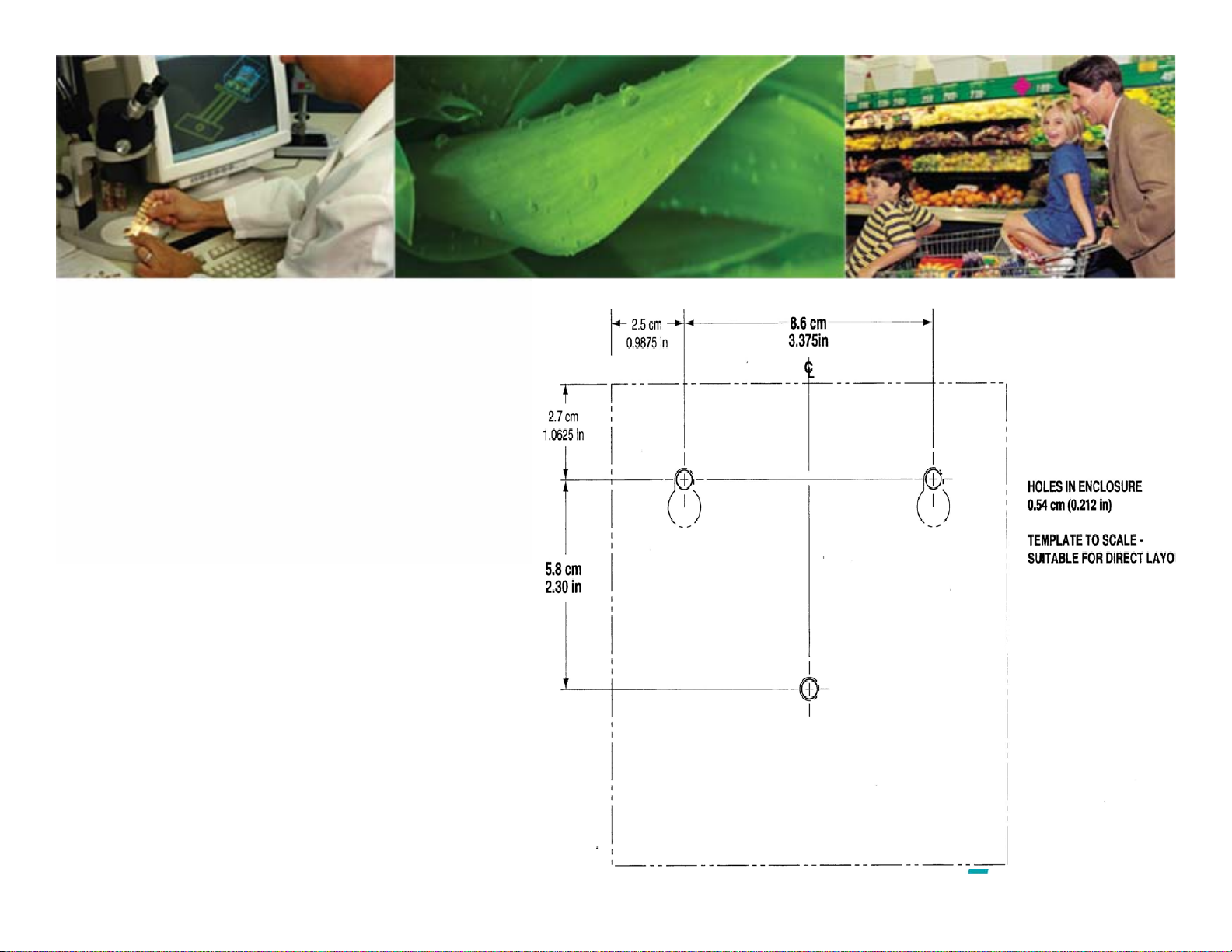
• Pick a spot to the pumpbox(s)
on the wall over the dish tray
counter or behind the washer;
the former is preferred so it’s
easy for the dishwashers to
see and react to alarms.
• For solid or powder detergent
capsule bowls, be sure to
install in a location where it’s
easy for the dishwashers to
check and replace the capsule.
Mounting Location

• Connect tubes to standpipes as shown at
left. The standpipes come with nut fittings
to connect to standard 1/4” ID
detergent/sanitizer and 1/8” ID rinse
polyflow transport tubing
• For installations requiring a low level alarm
lance, you can either use a separate low
level lance, or a low level suction lance
such as 1201071 which clamps onto the
side of the drum
• If you want to use color transport tubing,
use ¼” OD blue polyflow 092384, ¼” OD
red polyflow 041771, and 1/4T -1/4T
compression fitting rinse tube 1205464,
and the detergent standpipe 035623
035623 Detergent 1/4” ID
18” long CPVC standpipe
050572 Rinse 1/8” ID 18”
long CPVC standpipe
TUBING: Chemical Pickup Lance
Connection
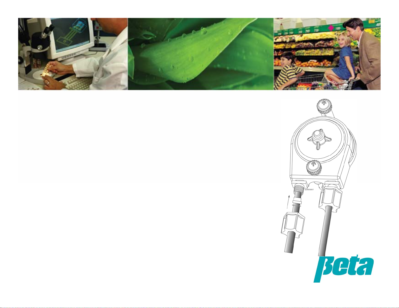
• The left side of the pump is the suction side which
should be connected to the chemical supply
• The right side of the pump is the chemical discharge
side which will be connected to injection fittings on
the washer
• Flex tubes are shipped outside of the cartridge so
they don’t seal shut during warm storage
• Loosen tube nuts, insert tubes, and tighten nuts as
shown
• Always point black SnapHead pins up or down and
push in to lock into place
TUBING: Pump Connection

• Mount the detergent bulkhead fitting in a 7/8” hole above the
water line, just above where the probe will be located. Make sur
e
the area has plenty of water circulation, such as an area near the
wash pump strainer inlet so the detergent will get circulated
immediately.
• Add 1/8” rinse injector (and any ¼” sanitizer injector) to rinse lin
e
in a location away from large amounts of steam or moving parts
which can induce thermal or physical fatigue on injector plastic
over time.
• If using a pressure switch, an injector with two connections is
required, one for the rinse and one for the sanitizer or copper
tubing line to the pressure switch. We recommend using a
stainless steel injection fitting if installing in a remote location,
since they are impervious to thermal and physical fatigue.
• Tubes connect to the fittings just like they do to pump nuts.
Don’t use an old hole if it’s in the wrong
spot! Making a new hole during
installation always takes less time than
getting a trouble call and making a new
hole on a separate trip
1/8” Rinse Injection Fitting 051467
1/4” Sanitizer Inj. Fitting 051466
Bulkhead Fitting for bowls 035542
Note: liquid detergent fitting
022031 comes with a ¼”
compression nut fitting.
Solid/powder bowls use a 5/8”
barb fitting 035542.
TUBING: Injection Fittings
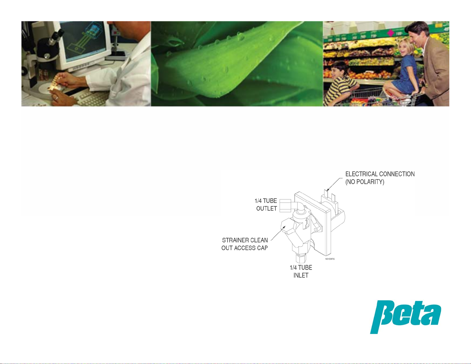
• Connect water supply tube to water
inlet on bottom of solenoid. Be sure
to verify which way the arrows point
on the solenoid, since standard
warewash solenoids have the water
inlet on the bottom whereas OPL
solenoids have it on the top.
• Connect outlet to bowl
• Mount bowl in a location where it
will be easy for the kitchen workers
to replace the detergent capsule
Solenoid & Bowl

• Connect detergent trigger wires to
“DETERGENT” and rinse solenoid wires to
“RINSE”, connecting one wire to HOT and
the other to the appropriate voltage (use
115 for 90-115V, and 230 for voltages a bit
over 230)
•WHT & BLK = 120V 50/60 Hz
• WHT& RED = 230V 50/60 Hz
•If you want to inject both detergent and
rinse using the rinse solenoid during the
rinse cycle, connect the trigger signal to one
side of the terminal block and jump the
signal to the other side.
If using a pressure switch, connect it to the
+RINSE green PCB connection
Terminal block before connecting power
wires
Terminal block after connecting power wires
WIRING: Trigger Connection
Other manuals for D3000
1
Table of contents
Other Beta Water Pump manuals


Popular Water Pump manuals by other brands


Sykes AmeriPumps
Sykes AmeriPumps GP100M Operation and maintenance instructions

DUROMAX
DUROMAX XP WX Series user manual

BRINKMANN PUMPS
BRINKMANN PUMPS SBF550 operating instructions

Franklin Electric
Franklin Electric IPS Installation & operation manual

Xylem
Xylem e-1532 Series instruction manual

Milton Roy
Milton Roy PRIMEROYAL instruction manual