BETE HydroWhirl Orbitor Instructions for use


BETE Fog Nozzle, Inc.
HydroWhirl®Orbitor Page 2 of 24
Contents
Maintenance 3
Recommended Tools List 5
Nozzle Head and Rear Plate – Disassembly 6
Body Shell and Inlet Casing – Disassembly 8
Turbine Shaft Subassembly – Disassembly 9
Gear Cartridge Subassembly – Disassembly 10
Main Body and Body Shell – Disassembly 11
Main Body and Body Shell – Reassembly 13
Gear Cartridge Subassembly – Reassembly 14
Turbine Shaft Subassembly – Reassembly 14
Body Shell and Inlet Casing – Reassembly 15
Nozzle Head and Rear Plate – Reassembly 16
Appendix 18
Parts List . . . . . . . . . . . . . . . . . . . . . . . . . . . . . . . . 21
Interchangeable Parts . . . . . . . . . . . . . . . . . . . . . . . . . 22
Recommended Spare Parts . . . . . . . . . . . . . . . . . . . . . . 23
www.BETE.com 20150421

BETE Fog Nozzle, Inc.
HydroWhirl®Orbitor Page 3 of 24
Maintenance
In order to prevent machine failures, routine maintenance should be
carried out every 500 hours of operation. This should include cleaning all
internal parts and assessing the wear of seals, gears, bearing and bushes.
Any fine solid particles left inside the machine will increase wear
considerably.
Please Note:
• The Orbitor requires no lubrication.
• The Orbitor is approved by Bureau Veritas; a copy of
certification can be provided upon request.
• The Orbitor is available with ATEX approval for Zone 0.
Attention
• Before maintenance can be carried out, it is important the machine is
not contaminated with chemicals that could be hazardous.
• Always use the tools stated throughout this manual. These can be
purchased from BETE.
• Always read the technical data thoroughly before carrying out any
work on this machine.
• Never service the Orbitor head while it is hot.
• After any maintenance is carried out it is essential the machine is
flushed and sterilized before further use.
• Any parts found to be unserviceable should be replaced before
further use.
• The machine should only be operated at temperatures below 95°C
(200°F)
• During operation, always ensure any tank openings are completely
sealed off and can withstand the full force of the striking jet.
• If the tank being cleaned contains a combustible liquid or vapor with a
risk of ignition or explosion, the Orbitor should be properly grounded.
www.BETE.com 20150421

BETE Fog Nozzle, Inc.
HydroWhirl®Orbitor Page 4 of 24
• The machine should be allowed to gradually reach its operating
pressure. A sudden spike could cause parts to wear prematurely or
fail.
Please Note – Any cleaning fluids must be stored/disposed of in
accordance with current rules/directives.
Please Note – Always record any wear found and ensure the machine
operates smoothly after maintenance.
www.BETE.com 20150421

BETE Fog Nozzle, Inc.
HydroWhirl®Orbitor Page 5 of 24
Recommended Tools List
• Allen Keys: (1) 6 mm and (1) 3 mm
• M12 Wrench
• Strap Wrench
• Screwdriver
• 3 mm Pin Punch
• Light Hammer
• Vice
• Spider Tool (Part No. DM00748)
• Set of (2) Side Plate Tools (Part No. DM00749 for the set)
• Nozzle Head Tool (Part No. DM00750)
• Loctite 638 (if ceramic seals are removed)
• Torque Wrench
• Fly-Press or Soft-Jawed Vice
www.BETE.com 20150421

BETE Fog Nozzle, Inc.
HydroWhirl®Orbitor Page 6 of 24
Nozzle Head and Rear Plate – Disassembly
Please refer to Figures 1 and 2.
1. Place the Orbitor in the vice, holding onto rear plate flats (DM02142).
Ensure machine is securely held in place before proceeding to the
next step.
2. Use tool (DM00750) to unscrew nozzle head (DM02141), in an
anti-clockwise direction.
Please Note – The assembly has 180° of lost motion.
3. The nozzle head (DM02141) should now be free to lift off.
4. Lift machine off the nozzle head shaft (DM02143).
Please Note – Be careful not to lose any seals, spacers or
bushes.
5. Check seal in nozzle head (DM00699) for wear or damage to the
seal lip, if excessively worn or damaged, then remove by cutting free.
6. There should be a ceramic seal insert (DM00698) left in the main
body. This should be replaced if the ceramic coating is chipped or
worn.
7. The bush (DM02032) will still be inside the main body (DM02139)
and should be carefully assessed for signs of wear.
8. The nozzle head bevel gear (DM02147) should still be on the nozzle
head shaft (DM02143) and should also be assessed for any signs of
wear to the gear teeth.
9. Inspect the stream straighteners for any foreign bodies and remove if
necessary.
10. Check rear plate seal (DM00699) for wear or damage to the seal lip.
11. Turn main body (DM02139) over and inspect second ceramic seal
insert for wear or damage.
12. Now both bushes (DM02032) in main head can be removed but only
if they are required to be replaced.
13. Lastly the nozzle head bevel gear (DM02147) can be lifted off the
nozzle shaft.
14. For Hi-capacity version see Figure 13.
www.BETE.com 20150421

BETE Fog Nozzle, Inc.
HydroWhirl®Orbitor Page 8 of 24
Body Shell and Inlet Casing – Disassembly
Inlet
Stator
DM00695
Rotor
DM00719
DM00696
Cartridge
Assembly
DM00685
DM00686
DM02923
DM02139
Figure 3: Body shell and inlet cas-
ing
1. Hold machine by inlet casing
at the bottom and turn the
body shell (DM02140) counter-
clockwise by hand, or alterna-
tively with a strap wrench if tight.
Please Note – To find part
number for a specific Inlet
Casing please refer to the
Interchangeable Parts list in
the Appendix as they vary by
model.
2. This should allow spring clip
(DM00686) to extrude from slot.
Unhook clip using a screwdriver.
3. Lift shell (DM02140) up from In-
let.
Please Note – You should be
left with the cartridge and tur-
bine subassemblies in inlet.
4. Pull out cartridge and turbine as-
semblies and inspect for wear.
5. Remove stator bush (DM00695)
if necessary.
www.BETE.com 20150421

BETE Fog Nozzle, Inc.
HydroWhirl®Orbitor Page 9 of 24
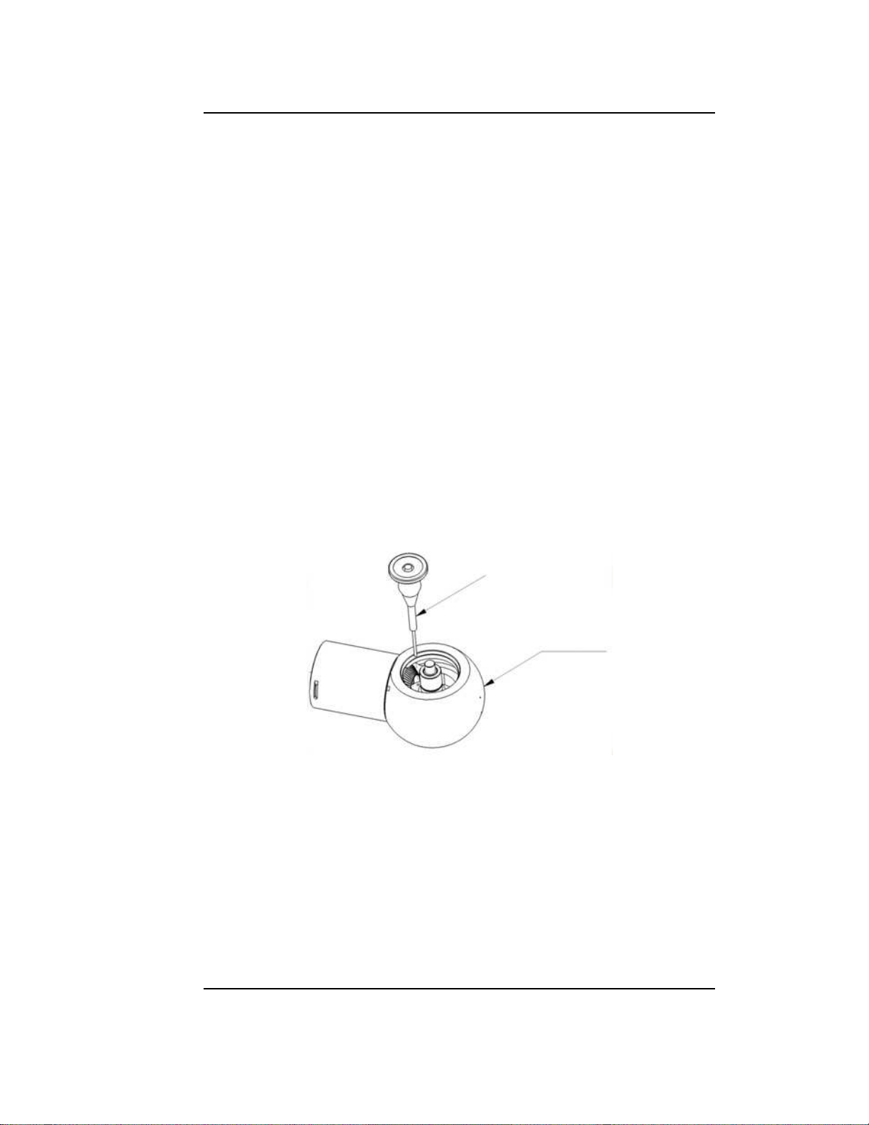
Turbine Shaft Subassembly – Disassembly
Please Note – Turbine can be removed from shaft if necessary by
unscrewing Hollow Set Screw (DM00702) (see Figure 4). For specific
turbine (rotor) part numbers refer to Interchangeable Parts list in the
Appendix as these vary depending on machine.
DM00702
DM00719
Rotor
Figure 4: Rotor (turbine) subassembly
www.BETE.com 20150421
BETE Fog Nozzle, Inc.
HydroWhirl®Orbitor Page 10 of 24
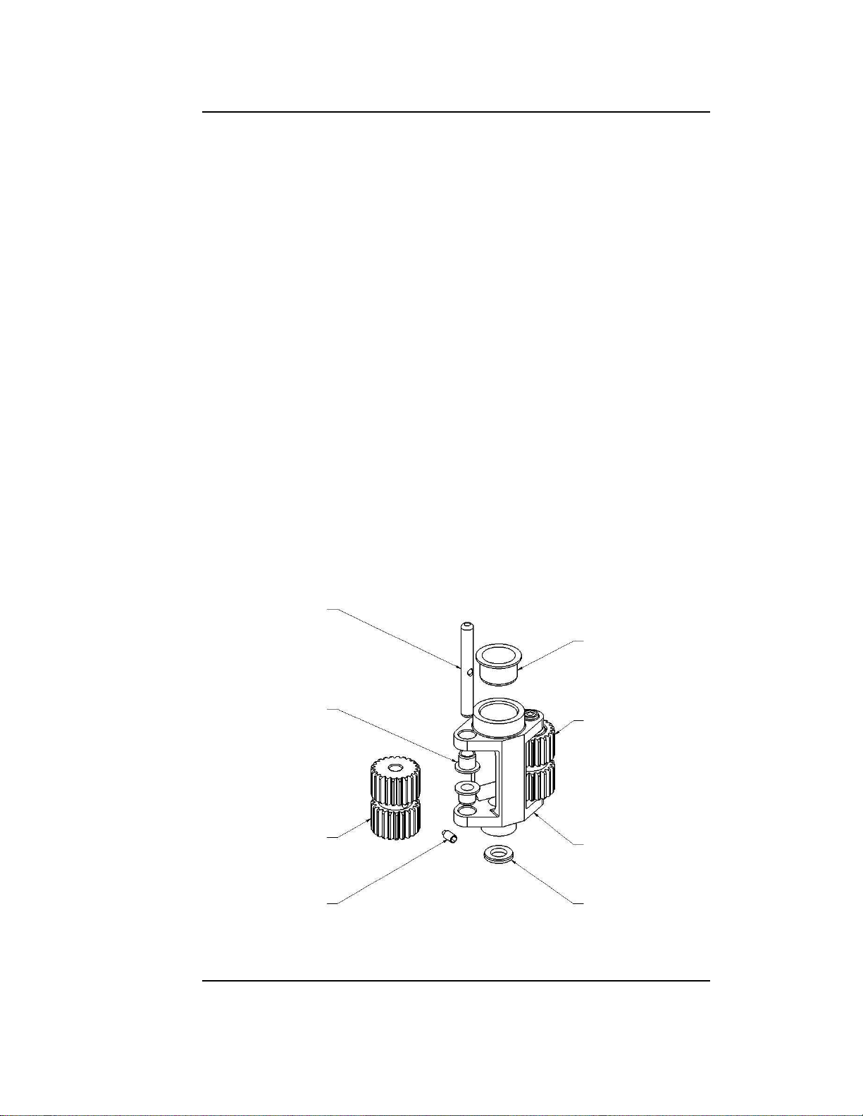
Gear Cartridge Subassembly – Disassembly
1. Check cartridge bush (DM00696), shaft bushes (DM00697), and
support washer (DM02226); inspect for wear.
2. Unscrew hollow set screws (DM00702) in both planet shafts, this
should allow you to remove both shafts (DM00736).
3. Now remove the planet gears; both the Aligned (DM00721) and the
1
/2Displaced (DM00722); check for wear.
DM00736
DM00697
DM00722
DM00702
DM00696
DM00721
DM02144
DM00685
Figure 5: Gear cartridge subassembly
www.BETE.com 20150421

BETE Fog Nozzle, Inc.
HydroWhirl®Orbitor Page 11 of 24
Main Body and Body Shell – Disassembly
Please Note – Before attempting to unscrew shell from main body,
ensure you knock pin out of main body using a 3mm pin punch
(Figure 6).
3mm Pin Punch
DM02139
Figure 6: 3mm Pin Punch
1. Fit the two side plate tools (DM00749) to the faces of the body and
place in vice.
2. Using spider tool (DM00748), loosen spider (DM02145 Figures 7
and 8) from main body.
3. Lift shell and spider from ball and separate internal components to
ensure all thrust bearing balls (DM00703) are retained. (Figure 8).
4. Inspect all seals, bearings, and bushes for signs of wear and replace
if necessary.
5. Check spider and bevel gear teeth for wear.
6. Check ceramic seal insert (DM00698) on body shell.
www.BETE.com 20150421

BETE Fog Nozzle, Inc.
HydroWhirl®Orbitor Page 13 of 24
Main Body and Body Shell – Reassembly
1. If removed, push ceramic seal inserts back into main body and body
shell using Loctite 638.
2. Re-assemble bearing assembly to spider and insert into body shell.
3. Pick up the main body and place the side plate tools on the sides of
main body and hold in vice.
Please Note – This is to protect the ceramic seal inserts.
4. Insert seal (DM00698) to top of main body, if removed.
5. Locate spider using spider tool and screw assembly to main body
through body shell. Using Loctite 638 on thread of spider shaft.
6. Using torque wrench, tighten spider to 60 N·m (45 ft·lbf).
7. Remove whole assembly from vice and remove side plates.
8. Replace 3mm pin (DM00709) in hole inside main body.
3mm Pin Punch
DM02139
Figure 9: 3 mm Pin Punch
www.BETE.com 20150421

BETE Fog Nozzle, Inc.
HydroWhirl®Orbitor Page 14 of 24
Gear Cartridge Subassembly – Reassembly
1. Replace cartridge bush (DM00696), shaft bushes (DM00697), and
support washer (DM02226) if removed.
2. Slide both gears into place and insert shafts aligning holes in gears
and shafts for hollow set screw.
3. Insert set screw (DM00702) and tighten.
Turbine Shaft Subassembly – Reassembly
Please Note – Turbine can be replaced on shaft if necessary by
sliding onto shaft and reinserting hollow set screw (DM00702). For
turbine part number refer to the Interchangeable Parts list in the
Appendix.
www.BETE.com 20150421

BETE Fog Nozzle, Inc.
HydroWhirl®Orbitor Page 15 of 24
Body Shell and Inlet Casing – Reassembly
Inlet
Stator
DM00695
Rotor
DM00719
DM00696
Cartridge
Assembly
DM00685
DM00686
DM02923
DM02139
Figure 10: Body shell and
inlet casing
1. Hold machine with main body
(DM02139)under body shell (DM02923)
and insert gear cartridge subassembly.
2. Insert turbine shaft subassembly guiding
turbine into cartridge.
Please Note – Check for smooth oper-
ation by spinning the turbine shaft by
hand.
3. Replace stator bush (DM00695) in stator
inside inlet casing, if removed.
4. Hold machine with main body under
body shell and slide the inlet casing into
body shell.
Please Note – Ensure hole in inlet
casing is aligned with slot in main
body shell.
5. Fit spring clip through slot in the shell
into the hole in the inlet connection and
turn slightly to locate in its position.
6. Rotate machine vertically and hold inlet
connection in vice, located on flats.
7. Turn shell 360°clockwise to fit spring clip
completely in inlet connection.
Please Note – Use new spring clip (DM00686) if necessary.
Please Note – Tighten with strap wrench if necessary.
www.BETE.com 20150421

BETE Fog Nozzle, Inc.
HydroWhirl®Orbitor Page 16 of 24
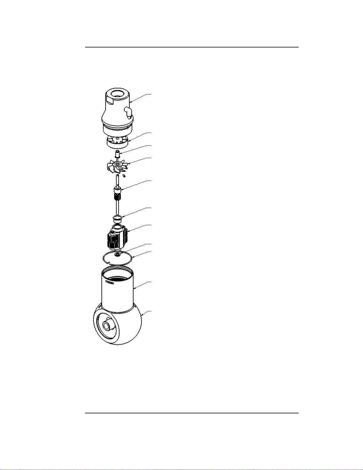
Nozzle Head and Rear Plate – Reassembly
Please refer to Figures 11 and 12.
1. Hold rear plate in vice using flats and place new seal, if necessary.
2. Slide nozzle head bevel gear onto nozzle shaft.
3. Push bushes (DM02032) into main body if necessary and slide
assembly back onto nozzle shaft.
4. Fit stainless steel spacer (DM02221) onto nozzle shaft.
5. If nozzles were removed now replace nozzles to nozzle head.
Please Note – Ensure nozzles are tightened sufficiently in order
to avoid machine failure.
6. Locate seal into grove of nozzle head.
7. Finally screw nozzle head back onto main assembly using Loctite
638 and tighten with tool (DM00750) to 60 N·m (45 ft·lbf).
8. For Hi-capacity version, see Figure 13.
9
DM02142
DM02147
DM02143
DM00699
DM00698
DM02139
DM02032
DM02032
Figure 11: Back plate reassembly
www.BETE.com 20150421


BETE Fog Nozzle, Inc.
HydroWhirl®Orbitor Page 20 of 24
Inlet
Stator
DM00695
Rotor
DM00702
DM00719
DM00696
DM00721
DM00685
DM00686
DM00693
DM02145
DM02135
DM02135
DM00703
DM02923
DM02142
DM00699
DM00699
DM02143
DM02147
DM02032
DM02032
DM02139
DM00698
DM02221
DM02141
Stream
Straightener
Nozzle
DM00709
DM00699
DM00698
DM00688
DM00722
DM00697
DM00736
Figure 15: Exploded view of the Orbitor
www.BETE.com 20150421
Other manuals for HydroWhirl Orbitor
1
Table of contents
Other BETE Washer manuals


