BETE HydroWhir Orbitor 100 Instructions for use
HydroWhirl® Orbitor 100
Tank Washing Machine
Instruction and Maintenance Manual
BETE Fog Nozzle Inc.
www.bete.com

BETE Fog Nozzle, Inc.
HydroWhirl® Orbitor 100
Page 2 of 40
www.BETE.com
20230927
Contents
Introduction to the Orbitor 100 Tank Washing Machine 5
Component Names ..............................................................................5
Operation Principles .............................................................................5
Performance and Technical Data 8
Operating Conditions ............................................................................8
Dimensions .......................................................................................... 8
Cleaning Fluids ....................................................................................9
Construction Materials ..........................................................................9
Performance Table ............................................................................. 10
Quick Wash or Rinse .......................................................................... 10
Installation, Mounting, and Washing Fluid Connection 10
Installation Checklist ........................................................................... 16
Mounting - Loads and Weights ...........................................................17
Fixed Installations ............................................................................... 17
Portable Installations .......................................................................... 18
Operation Instructions 18
Conditions for Safe Working ...............................................................18
General Operating Instructions ...........................................................19
Maintenance Manual 20
Schedule ............................................................................................ 20
Recommended Tools List.................................................................... 21
Disassembly Operations 22
Nozzle Head and Retaining Head Bolt – Disassembly ....................... 22
Body Shell and Inlet Casing – Disassembly ....................................... 24

BETE Fog Nozzle, Inc.
HydroWhirl® Orbitor 100
Page 3 of 40
www.BETE.com
20230927
Rotor Shaft Subassembly – Disassembly .......................................... 25
Gear Cartridge Subassembly – Disassembly ..................................... 26
Main Body and Body Shell – Disassembly ......................................... 27
Inspection .......................................................................................... 29
Seal Insert Removal ........................................................................... 30
Reassembly Operations 31
Main Body and Body Shell – Reassembly .......................................... 31
Gear Cartridge Subassembly - Reassembly ...................................... 31
Rotor Shaft Subassembly – Reassembly ........................................... 32
Body Shell and Inlet Casing – Reassembly ........................................ 33
Nozzle Head and Retaining Head Bolt – Reassembly ........................ 34
Parts List 35
Interchangeable Parts ......................................................................... 37
Service Tool Kit .................................................................................. 38
Rebuild Kits ........................................................................................ 38

BETE Fog Nozzle, Inc.
HydroWhirl® Orbitor 100
Page 4 of 40
www.BETE.com
20230927
Contact Details
For technical support, replacement parts, or additional equipment, please
contact us at:
BETE Fog Nozzle, Inc.
50 Greenfield St
Greenfield MA 01301 USA
Telephone: +1 (413) 772-0846
Fax: +1 (413) 772-6729
Email: sales@bete.com
Web: http://www.bete.com

BETE Fog Nozzle, Inc.
HydroWhirl® Orbitor 100
Page 5 of 40
www.BETE.com
20230927
Introduction to the Orbitor 100 Tank Washing Machine
This document is the Installation, Operation and Maintenance Manual,
also known as the Product Manual, for the Orbitor 100 Tank Washing
Machine (TWM). These machines are supplied for use in the marine,
industrial, and food processing industries.
Component Names
For part numbers and names see the Maintenance Manual section starting
on page 20. The figures shown throughout the manual are typical of a 4
nozzle machine. These examples may not directly resemble the machine
supplied but are fundamentally the same in construction and part
materials.
Operation Principles
The basic tank cleaning process is achieved by impinging high impact
cleaning fluid jets on the inner walls of the vessel. The TWM action moves
the jet nozzles in a spiral pattern that ensures correct and even coverage
of the vessels surfaces through a washing cycle.
The flow of the cleaning fluid drives the machine causing the spherical
body and nozzle head to rotate. There are no other power sources, control
systems or electrical devices. The mechanism is self-lubricated and
internally self-cleaned by the cleaning fluid. Three small fixed jets wash the
machine exterior. The Orbitor 100 TWM can be used with pressures as
low as 45 psi (3 bar) due to a very low starting torque.

BETE Fog Nozzle, Inc.
HydroWhirl® Orbitor 100
Page 6 of 40
www.BETE.com
20230927
Inlet
Casing
Nozzle Head
Nozzle
Main Body
Figure 1: General arrangement.
BETE Fog Nozzle, Inc.
HydroWhirl® Orbitor 100
Page 7 of 40
www.BETE.com
20230927
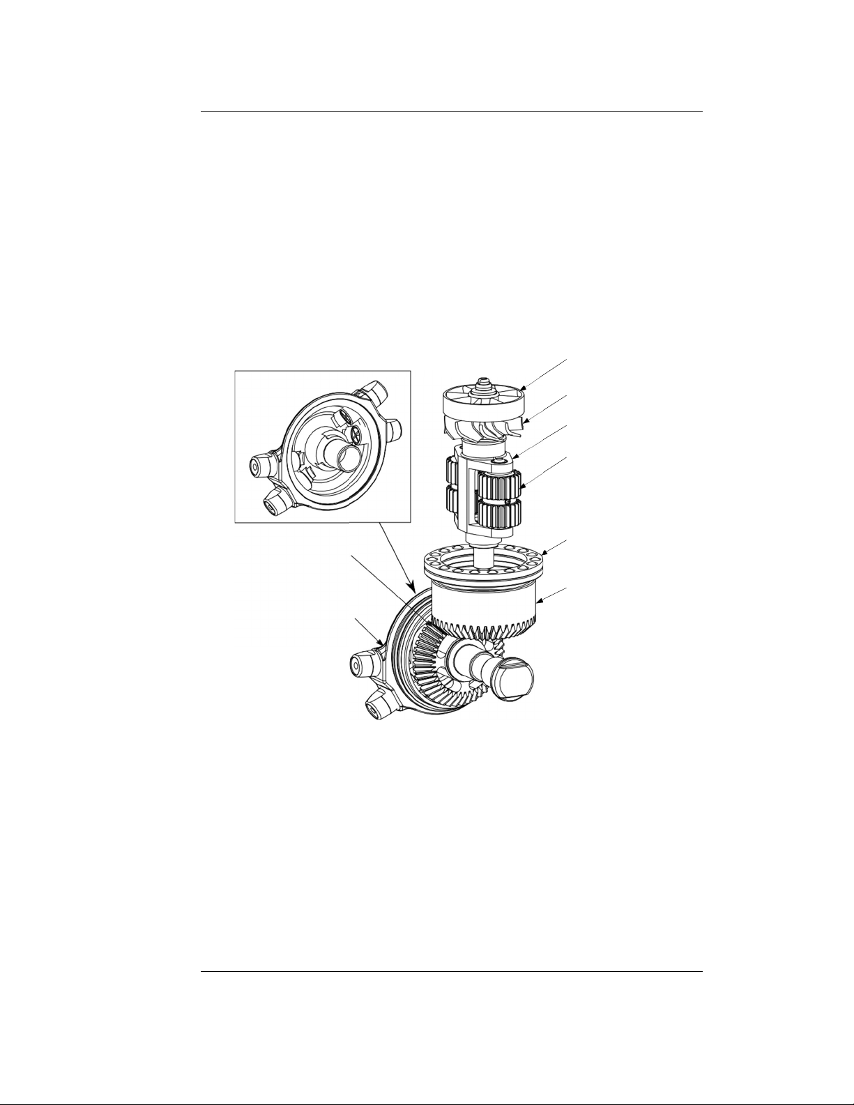
Stator
Rotor
Gear Cartridge Ass’y
Planet Gear
Nozzle Head Bevel Gear
Nozzle Head
Ball Thrust Bearing
(Top Race Removed)
Entry Bevel Gear
Figure 2: Orbitor 100 tank washing machine with housings removed.

BETE Fog Nozzle, Inc.
HydroWhirl® Orbitor 100
Page 8 of 40
www.BETE.com
20230927
Performance and Technical Data
Operating Conditions
Operating pressure range 3 bar to 10 bar 45 psi to 145 psi
Maximum pressure 12 bar 175 psi
Maximum operating temperature
95
◦
C
195 °F
Minimum ambient storage temperature
−40
◦
C
−40 °F
Maximum ambient storage temperature
140
◦
C
285 °F
Dimensions
Available inlet connections, 3/4 BSP (G) 3/4 NPT
female pipe thread 1 BSP (G) 1 NPT
Length, not including nozzles 193 mm 7.6 in
Width, not including nozzles 76 mm 3.0 in
Height 76 mm 3.0 in
Minimum opening diameter,
nozzles in any orientation
100 mm 4.0 in
Minimum opening diameter,
nozzles vertically aligned
85 mm 3.35 in
Installed weight, approximate 2.5 kg 5.5 lb
Packed Dimensions
Length
545 mm
21.5 in
Width 270 mm 10.6 in
Height 280 mm 11.0 in
Total gross weight < 4 kg < 9 lb

BETE Fog Nozzle, Inc.
HydroWhirl® Orbitor 100
Page 9 of 40
www.BETE.com
20230927
Cleaning Fluids
Orbitor 100 TWMs are capable of resisting most cleaning fluids provided:
•
They contain no
–
Solid abrasive particles
–
Chemicals liable to attack the TWM construction materials. See
materials list below.
•
Temperatures specified in Operating Conditions are not exceeded
Approved cleaning fluids:
•
Water at a temperature below 200 °F (below 95 ◦C)
•
< 5 % NaOH caustic soda solution
•
Other cleaning fluids can be used with advice of BETE
Construction Materials
Component Material
Nozzle head, nozzles and inter-
nal parts unless specified below
316L stainless steel
Body shell Kolsterised 316L stainless steel
Gears PEEK
(PVDF or other materials available
by special order)
Seals PTFE, 10 % carbon filled
Seal seats Ceramic coated
Bushings PTFE, carbon filled
Ball bearings / race Kolsterised 316 stainless steel
Duplex 2205 steel (hardened)
Please note – Do not use any chemicals on the TWM while cleaning
that might affect the integrity of the non-metallic component parts. If
in doubt contact BETE for advice.

BETE Fog Nozzle, Inc.
HydroWhirl® Orbitor 100
Page 10 of 40
www.BETE.com
20230927
Performance Table
Tables 1 – 4 show total water flow, total jet length (effective cleaning may
vary based on application), and typical cycle time for various nozzle
configurations and sizes at different pressures.
Quick Wash or Rinse
The cycle times defined in the above table are for a full wash cycle.
Wash cycles can be repeated as many times as necessary. The TWM can
also be stopped after one pattern generation for a quick rinse.
Installation, Mounting, and Washing Fluid Connection
Correct installation of an Orbitor 100 TWM is the responsibility of the tank
owners, constructors, or installers. Mounting and connecting is a
straightforward task for a competent fitter or technician.
BETE is happy to offer technical support and recommendations upon
request but does not normally carry out installation work and cannot be
responsible for ensuring correct installation practice or application.
TWM machine installation - key points:
•
Machines will be positioned in the tank to permit the best cleaning jet
coverage of walls, floor and tank cover.
•
The cleaning pattern required and selection of flow and jet length
depends on:
–
Tank dimensions.
–
Properties of the stored product residue.
–
Available flow and pressure.
•
The axis of rotation of the spherical main body is along the axis of
the inlet.
•
The axis of rotation of the nozzle head is perpendicular to inlet axis
— see Fig. 3).
•
Machines will normally be mounted to the tank top cover and project
down.

Table 1
Orbitor 100 Performance Information, US Units
4 ×,03.0 4 ×,04.0 4 ×,05.0 4 ×,06.0
Pressure Flow
Jet
Length
Cycle
Time
Flow
Jet
Length
Cycle
Time
Flow
Jet
Length
Cycle
Time
Flow
Jet
Length
Cycle
Time
psi gpm ft min gpm ft min gpm ft min gpm ft min
45 12.0
3.3 6.0
17.8
6.6 5.4
23.7
8.2 4.4
30.6
9.8 3.9
60 13.9
4.9 5.4
20.3
8.2 4.7
26.7
9.8 3.9
34.0
11.5 3.4
75 15.8
6.6 4.8
22.7
9.8 4.1
29.6
11.5 3.4
37.3
13.1 3.0
90 17.6
6.6 4.3
25.1
9.8 3.6
32.3
11.5 3.0
40.6
13.1 2.6
100 18.8
8.2 4.0
26.6
11.5 3.3
34.1
13.1 2.8
42.8
14.8 2.4
115 20.5
8.2 3.6
28.9
11.5 2.9
36.7
13.1 2.4
46.0
14.8 2.1
130 22.2
9.8 3.2
31.2
13.1 2.7
39.1
14.8 2.2
49.2
16.4 1.9
145 23.9
11.5 2.9
33.4
13.1 2.5
41.4
14.8 2.0
52.4
16.4 1.7
BETE Fog Nozzle, Inc.
HydroWhirl
®
Orbitor 100
Page 11 of 40
www.BETE.com
20230927
8

Table 2
Orbitor 100 HR Performance Information, US Units
4 ×,03.0 4 ×,04.0 4 ×,05.0 4 ×,06.0
Pressure Flow
Jet
Length
Cycle
Time
Flow
Jet
Length
Cycle
Time
Flow
Jet
Length
Cycle
Time
Flow
Jet
Length
Cycle
Time
psi gpm ft min gpm ft min gpm ft min gpm ft min
45 12.9
12.5 19.5
16.5
14.4 25.5
24.2
16.4 16.3
30.6
18.0 21.5
60 14.2
14.9 16.8
19.2
17.1 21.6
26.9
19.1 14.1
34.0
20.6 18.7
75 15.7
17.0 14.6
21.8
19.4 18.3
29.6
21.4 12.2
37.3
22.9 16.3
90 17.2
18.8 12.8
24.2
21.3 15.7
32.2
23.2 10.9
40.6
24.7 14.3
100 18.3
19.8 11.8
25.7
22.3 14.2
33.8
24.3 10.2
42.8
25.7 13.2
115 20.1
21.0 10.7
27.9
23.6 12.5
36.3
25.4 9.6
46.0
26.9 11.8
130 21.9
22.0 10.0
29.9
24.5 11.5
38.7
26.2 9.5
49.2
27.8 10.8
145 23.8
22.6 9.7
31.8
25.0 11.0
40.9
26.6 9.8 52.4
28.2 10.3
BETE Fog Nozzle, Inc.
HydroWhirl
®
Orbitor 100
Page 12 of 40
www.BETE.com
20230927

Table 3
Orbitor 100 Performance Information, SI Units
4 ×,03.0 4 ×,04.0 4 ×,05.0 4 ×,06.0
Pressure Flow
Jet
Length
Cycle
Time
Flow
Jet
Length
Cycle
Time
Flow
Jet
Length
Cycle
Time
Flow
Jet
Length
Cycle
Time
bar L/min
m
min L/min
m
min L/min
m
min L/min
m
min
3
45.0
1.0 6.0
66.7
2.0 5.5
88.3
2.5 4.5
115 3.0 4.0
4
51.7
1.5 5.5
75.0
2.5 4.8
100 3.0 4.0
127 3.5 3.5
5
58.3
2.0 5.0
85.0
3.0 4.3
110 3.5 3.5
138 4.0 3.0
6
65.0
2.0 4.4
93.3
3.0 3.8
120 3.5 3.0
152 4.0 2.7
7
71.7
2.5 4.0
102 3.5 3.3
130 4.0 2.8
163 4.5 2.4
8
78.3
2.5 3.5
110 3.5 2.9
140 4.0 2.5
175 4.5 2.1
9
85.0
3.0 3.1
118 4.0 2.6
148 4.5 2.1
187 5.0 1.8
10 90.0
3.5 3.0
127 4.0 2.5
157 4.5 2.0
198 5.0 1.8
BETE Fog Nozzle, Inc.
HydroWhirl
®
Orbitor 100
Page 13 of 40
www.BETE.com
20230927

Table 4
Orbitor 100 HR Performance Information, SI Units
4 ×,03.0 4 ×,04.0 4 ×,05.0 4 ×,06.0
Pressure Flow
Jet
Length
Cycle
Time
Flow
Jet
Length
Cycle
Time
Flow
Jet
Length
Cycle
Time
Flow
Jet
Length
Cycle
Time
bar L/min
m
min L/min
m
min L/min
m
min L/min
m
min
3
48.3
3.7 20.0
61.7
4.3 26.0
90.0
4.9 17.0
115 5.4 22.0
4
53.3
4.5 17.0
71.7
5.1 22.0
102 5.7 14.0
127 6.2 19.0
5
57.5
5.1 14.5
80.0
5.8 19.0
110 6.4 12.0
138 6.9 16.5
6
64.2
5.6 13.0
90.0
6.4 16.0
120 7.0 11.0
152 7.4 14.5
7
70.0
6.1 12.0
98.0
6.8 14.0
128 7.4 10.5
163 7.9 13.0
8
76.7
6.4 10.8
107 7.2 12.5
138 7.8 10.0
175 8.2 12.0
9
83.3
6.7 10.0
113 7.5 11.5
147 8.0 9.5
187 8.5 11.0
10 90.0
6.9 9.5
120 7.6 11.0
155 8.1 9.5
198 8.6 10.0
BETE Fog Nozzle, Inc.
HydroWhirl
®
Orbitor 100
Page 14 of 40
www.BETE.com
20230927

BETE Fog Nozzle, Inc.
HydroWhirl® Orbitor 100
Page 15 of 40
www.BETE.com
20230927
Figure 3: Rotation direction of nozzle head and body.
•
Machines may also be inverted and project through the tank floor.
– Please assume the vertical down orientation in following text.
•
BETE or its agents will be pleased to offer application and installation
advice and can produce cleaning diagrams (also known as shadow
diagrams) if required (refer to the Installation Checklist provided in
this document).
The inlet comprises a cylindrical housing with an internal (female) thread
sized for alternative pipe thread systems. The standard internal threads
are:
3/4 NPT 3/4 BSP (G)
1 NPT 1 BSP (G)
This threaded interface provides both fluid connection and structural
machine mounting functions. It is recommended to install a coarse filter of
0.06 in (1.5 mm) minimum mesh in the supply line.

BETE Fog Nozzle, Inc.
HydroWhirl® Orbitor 100
Page 16 of 40
www.BETE.com
20230927
Installation Checklist
TWM Serial Number
Location of TWM Installation
Date
Stage Task
✓
Details Name of Technician
Pre-Installation
Has a system level
Hazard
Analysis
been
conducted?
Is
the
cleaning
fluid
supply
filtered?
Test
and
record
cleaning
fluid
supply
pressure.
Record
here
the
normal
cleaning
fluid
specification
and
temperature.
Post-Installation
Check pipe tightness.
Check nozzle
tightness.
Test electrical
resistance between
nozzle
tips
and
installation
pipe
and
tank structure.
Test electrical
resistance
of
portable
hoses.
Rinse the system with
clean water.
Test for smooth
operation
and
regular
running speed.

BETE Fog Nozzle, Inc.
HydroWhirl® Orbitor 100
Page 17 of 40
www.BETE.com
20230927
Mounting - Loads and Weights
Tank owners, constructors, or installers are responsible for the structural
integrity of the TWM mounting. The installation specification and design
should consider the following.
•
Maximum static weight is 5.5 lb (2.5 kg, 24.5 N).
–
Weight of pipe work and fluids are additional.
•
Single nozzle reaction forces can be up to 9 lb (40 N) depending on
pressure and nozzle size.
–
Normally these forces are balanced by opposing nozzles.
•
Structural strength and stiffness of the mounting must be sufficient.
–
The natural vibration frequency of the mounting must be many
times the forcing frequency.
–
Masonry vessels are a particular concern and may require
manufacture of large pipe flanges or structures to spread loads.
•
Pipe work systems must be designed to prevent water hammer
effects.
–
Forces produced by water hammer can far exceed normal
reaction loads and can damage the TWM and supply pipework.
•
Installations must be designed by a competent engineer or other
qualified individual.
Fixed Installations
Fixed machines are used for applications where the stored media or
process will not be affected by the presence of a permanent machine. This
type of installation requires the least operator intervention and the lowest
component costs. In practice, specification differences between fixed and
portable machines are few.
The fluid coupling and machine mounting is specific to each tank
installation. Normally, fixed machines are mounted on rigid pipes, often
flange mounted to the tank roof or floor. BETE can supply suitable flanged
and weld prepared pipe assemblies. Pipe length depends on tank size and
required jet pattern. Short flanged pipes form a compact unit ideal for top
down washing.

BETE Fog Nozzle, Inc.
HydroWhirl® Orbitor 100
Page 18 of 40
www.BETE.com
20230927
Longer pipes, also known as Drop Pipes or Free Standing Units (FSU’s),
will require additional strengthening to prevent fatigue fracture due to
vibration. Long pipe installations are designed in collaboration with the
customer and often include steadying cable rigs or tie bars.
A machine fixed in a dirty environment might experience the nozzles
becoming blocked by the contaminant which will affect the machines
performance. If this condition is likely to occur, inspection and cleaning of
the nozzles prior to use is advised.
Ensure all fixed installations are clear from any obstructions that might
prevent the nozzle head from rotating.
Portable Installations
Portable machines are only needed while cleaning and are moved out the
way during normal operation. The equipment is stowed when not in use.
Portable machines are most often used with a large bore flexible hose with
pipe threaded end couplings. Flexible hose mounting allows the cleaning
machine to be guided into different positions in the tank with manually
controlled cables. The TWM operator can thereby concentrate the
cleaning action in particularly stubborn areas.
Operation Instructions
Conditions for Safe Working
•
Only competent and qualified persons should carry out and check
installation work.
•
Follow the installation instructions in this manual.
•
Complete the Installation Checklist printed in this manual.
–
Record installation details.
–
Store manuals with check lists appropriately in an accessible
location.
•
Use Orbitor 100 TWMs within the technical parameters defined in the
Operating Conditions.
•
Ensure that personnel cannot touch hot TWM surfaces or be hit by
high power cleaning fluid jets.

BETE Fog Nozzle, Inc.
HydroWhirl® Orbitor 100
Page 19 of 40
www.BETE.com
20230927
–
Beware of hazardous cleaning fluids.
•
Maintain Orbitor 100 TWMs in accordance with the instructions
provided in this Product Manual.
–
Check nozzle tightness regularly.
General Operating Instructions
•
Always
–
Rinse with clean water after operation.
–
Ensure that any tank openings are completely sealed off and
can withstand the full force of the striking jet.
–
Allow the machine to gradually reach its operating pressure to
avoid water hammer effects. A sudden spike could cause parts
to wear prematurely or fail.
–
Store and dispose of cleaning fluids in accordance with current
rules and directives.
•
Never
–
Back drive the TWM by manually rotating nozzle heads.
–
Drive the TWM with steam or with a liquid at a temperature
above 200 °F (95 ◦C).

BETE Fog Nozzle, Inc.
HydroWhirl® Orbitor 100
Page 20 of 40
www.BETE.com
20230927
Maintenance Manual
The Orbitor 100 TWM is designed to allow for field maintenance. These
machines may also be returned to BETE for maintenance if desired. To
ensure correct operation of the machine, it is mandatory that all spare
parts be supplied by BETE.
Once maintenance has been carried out by either party the installation test
procedure must be conducted on reinstallation. A new Installation
Checklist is required to be completed and maintained.
Schedule
In order to prevent machine failures, routine maintenance should be
carried out at a maximum of
500 hours of operation
Maintenance should include cleaning all internal parts and assessing the
wear of seals, gears, bearing and bushes.
•
Any fine solid particles left inside the machine will increase wear
considerably.
•
Orbitor 100 TWM requires no lubrication.
–
The Orbitor 100 TWM is lubricated by the spray media during
operation.
Attention
•
Before maintenance can be carried out, it is important the machine is
not contaminated with chemicals that could be hazardous.
•
Always
–
Use the tools stated throughout this manual. Special tools for
Orbitor 100 maintenance can be purchased from BETE.
–
Read the technical data thoroughly before carrying out any work
on this machine.
–
Record any wear found and check for smooth operation of the
machine after maintenance.
Table of contents
Other BETE Washer manuals


