BEVOi BVIREF18SS User manual

BEVOi
INSTRUCTION
MANUAL
Models:
BVIREF18SS
BVIREF18W
o
o
o
o
5.
Please
read
the
Manual
carefully
before
use.
The
Manual
shall
be
kept
in
good
custody
for
later
reference

Contents
1.
SAFETY
WARNINGS.
2
2.
INSTALLTION....
2
2.1
Location
2.2
Door
Handle
Install
2.3
Reversing
the
Door
Swing(optional)
2.4
Door
Space
Requirements
2.5
Leveling
the
Unit
2.6
Cleaning
Before
Use
2.7
Before
Using
Your
Unit
2.8
Interior
Accessories
2
,.3
6
6
6
7
.7
7
2.9
Icemaker
Installation
2.10
Connecting
ice
Maker
to
Water
Suppiy
3.
PRODUCT
OVERVIEW
12
14
14
4.
OPERATION.
14
4.1
Key
4.2
Display
Screen
4.3
Display
4.4
Shift
Setting
4.5
The
Standby
Controi
Function
4.6
Fault
Indication
14
15
15
..
15
15
15
4.7
Temperature
Control
Operation
5.
CLEANING
5.1
Defrosting
5.2
Cleaning
the
Interior
and
the
Exterior
of
the
Unit
5.3
Cleaning
Tips
6.
MAINTENANCE
6.1
Changing
the
Internal
Light
6.2
Care
When
Handling
/
Moving
Your
Unit
6.3
Servicing
6.4
Switching
Off
for
Long
Periods
of
Time
7.
Troubleshooting
7.1
Warm
tips
16
16
16
16
16
16
16
16
16
17
17
2.
INSTALLATION
2.1
Location
When
selecting
a
position
for
your
unit
you
should
make
sure
the
floor
is
flat
and
firm,
and
the
room
is
well
ventilated.
Avoid
locating
your
unit
near
a
heat
source,
e.g.
cooker,
boiler
or
radiator.
Also
avoid
direct
sunlight
as
it
may
increase
the
electrical
consumption.
Extreme
cold
ambient
temperatures
may
also
cause
the
unit
not
to
perform
properly.
This
unit
is
not
designed
for
use
in
a
garage
or
outdoor
installation.
Do
not
drape
the
unit
with
any
covering.
When
installing
the
unit,
ensure
that
3
inch
of
free
space
is
left
at
both
sides,
1
inch
at
the
rear
and
1
inch
at
the
top
of
the
unit.
This
will
allow
cold
air
to
circulate
around
the
refrigerator
and
improve
the
efficiency
of
the
cooling
process.
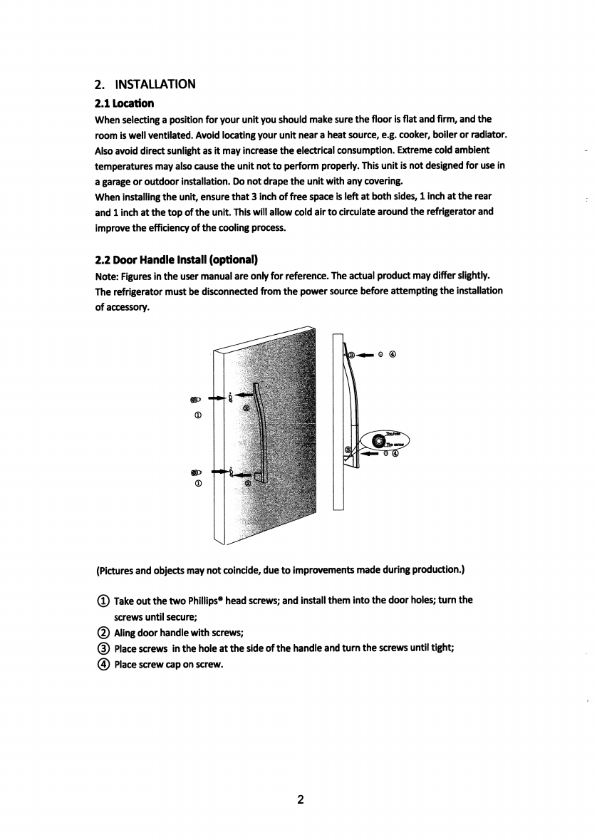
2.2
Door
Handle
Install
(optional)
Note:
Figures
in
the
user
manual
are
only
for
reference.
The
actual
product
may
differ
slightly.
The
refrigerator
must
be
disconnected
from
the
power
source
before
attempting
the
installation
of
accessory.
C
8
»>
(D
●●r:
QlJ
■'A
(Pictures
and
objects
may
not
coincide,
due
to
improvements
made
during
production.)
Take
out
the
two
Phillips®
head
screws;
and
install
them
into
the
door
holes;
turn
the
screws
until
secure;
Aling
door
handle
with
screws;
Place
screws
in
the
hole
at
the
side
of
the
handle
and
turn
the
screws
until
tight;
Place
screw
cap
on
screw.
@
@
2

1.
SAFETY
WARNINGS
Warning:
Risk
of
fire/flammable
materials
RECOMMENDATIONS:
This
appliance
is
intended
to
be
used
in
household
and
similar
applications
such
as
staff
kitchen
areas
in
shops,
offices
and
other
working
environments;
farmhouses
and
by
clients
in
hotels,
motels
and
other
residential
type
environments;
bed
and
breakfast
type
environments;
catering
and
similar
non-retail
applications.
If
the
supply
cord
is
damaged,
it
must
be
replaced
by
the
manufacturer,
its
service
agent
or
similarly
qualified
persons
in
order
to
avoid
a
hazard.
Do
not
store
explosive
substances
such
as
aerosol
cans
with
a
flammable
propellant
in
this
appliance.
The
appliance
has
to
be
unplugged
after
use
and
before
carrying
out
user
maintenance
on
the
appliance.
●
WARNING:
Keep
ventilation
openings,
in
the
appliance
enclosure
or
in
the
built-in
structure,
clear
of
obstruction.
●
WARNING:
Do
not
use
mechanical
devices
or
other
means
to
accelerate
the
defrosting
process,
other
than
those
recommended
by
the
manufacturer.
●
WARNING:
Do
not
damage
the
refrigerant
circuit.
●
WARNING:
Do
not
use
electrical
appliances
inside
the
food
storage
compartments
of
the
appliance,
unless
they
are
of
the
type
recommended
by
the
manufacturer.
●
WARNING;
Please
discard
the
refrigerator
according
to
local
regulators
for
it
use
flammable
blowing
gas
and
refrigerant.
●
WARNING:
When
positioning
the
appliance,
ensure
the
supply
cord
is
not
trapped
or
damaged.
●
WARNING:
Do
not
locate
multiple
portable
socket-outlets
or
portable
power
supplies
at
the
rear
of
the
appliance.
●
Do
not
use
extension
cords
or
ungrounded
(two
prong)
adapters.
●
DANGER:
Risk
of
child
entrapment.
Before
you
throw
away
your
old
refrigerator
or
freezer:
●
Take
off
the
doors.
●
Leave
the
shelves
in
place
so
that
children
may
not
easily
climb
inside.
The
refrigerator
must
be
disconnected
from
the
source
of
electrical
supply
before
attempting
the
installation
of
any
accessory.
Refrigerant
and
cyclopentane
foaming
material
used
for
the
refrigerator
are
flammable.
Therefore,
when
the
refrigerator
is
discarded,
it
shall
be
kept
away
from
any
fire
source
and
recovered
by
a
special
recovering
company
with
corresponding
qualification
other
than
be
disposed
by
combustion,
so
as
to
prevent
damage
to
the
environment
or
any
other
harm.
Children
should
be
supervised
to
ensure
that
they
do
not
play
with
the
appliance.
This
appliance
is
not
intended
for
use
by
persons
(including
children
)
with
reduced
physical,
sensory
or
mental
capabilities,
or
lack
of
experience
and
knowledge,
unless
they
have
been
given
supervision
or
instruction
concerning
use
of
the
appliance
by
a
person
responsible
for
their
safety.
1*
1

2.3
Reversing
The
Door
Swing
Reversing
the
door
position
Parts
included
with
the
hinge
kit:
Parts
already
mounted
on
the
door
(as
shipped):
h
Center
right
hinge
Right
top
hinge
cover
Center
left
hinge
Left
top
hinge
cover
Top
right
hinge
Top
left
hinge
Screws
(4)
Upper
door
self-locking
block
Right
door-open
stopper
Plug
(4)
Door
block
Handle
assembly
Allen
wrench
Upper
door
self-locking
block
Left
door-open
stopper
Bottom
hinge
1.
Unplug
your
refrigerator
and
remove
alt
food
from
the
door
shelves.
2.
Remove
the
left
cover
plate
and
the
right
top
hinge
cover,
then
unscrew
and
remove
the
right
top
hinge.
Keep
the
screws
to
reuse.
/
\
Left
cover
plate
Right
top
hinge
cover
t
3.
Lift
the
freezer
door
up
and
away
from
your
refrigerator.
4.
Unscrew
the
three
screws
holding
the
center
hinge,
remove
the
hinge,
then
lift
the
refrigerator
door
up
and
away
from
your
refrigerator.
Save
the
screws
to
reuse.
t
3

Unscrew
the
two
screws
holding
the
bottom
hinge,
then
remove
the
bottom
hinge
from
the
bottom
ri
ght
side
of
the
refrigerator.
Unscrew
the
hinge
pin
from
the
right
side
of
the
bottom
hinge
and
move
it
to
the
ieft
side,
then
secure
the
bottom
hinge
to
the
bottom
left
side
of
the
refrigerator,
using
the
screws
you
removed
previously.
9.
Insert
the
plastic
bushings
into
the
left
sides
of
freezer
and
refrigerator
doors.
5.
©^r
6.
)
5
1
Reattach
the
bottom
hinge
Remove
the
bottom
hinge
Hinge
pin
10.
Remove
the
door
block
from
the
bottom,
right
side
of
the
door
and
attach
it
to
the
other
side.
Hinge
pin
7.
Remove
the
plastic
bushing
from
the
top
right
of
the
freezer
and
refrigerator
doors.
11.
Attach
the
ieft
upper
door
self-locking
biock
and
the
left
door-open
stopper
to
the
left
side
of
the
freezer
door.
5
1
Upper
door
self-lociting
block
8.
Remove
the
hole
cap
from
the
top
left
of
refrigerator
door
and
insert
it
in
the
other
side.
)
rj
)
h
Left
door-open
stopper
5
4

12.
Remove
the
right
upper
door
self-locking
block
and
the
right
door-open
stopper.
Store
in
a
safe
place
in
case
you
need
to
reverse
the
door
position
again.
13.
Remove
the
two
hole
caps
from
the
left
side,
where
the
center
hinge
will
go,
and
insert
them
into
the
other
side.
14.
Attach
the
refrigerator
door
on
the
bottom
hinge,
then
attach
the
center
left
hinge
to
the
left
side
of
the
refrigerator.
Attach
the
left
center
hinge
15.
Put
the
freezer
door
onto
the
center
left
hinge,
then
attach
the
top
left
hinge
to
the
top
of
refrigerator.
Cover
the
hinge
with
the
top
left
hinge
cover
and
cover
the
screw
holes
on
the
right
side
of
the
top
with
the
cover
plate
you
previously
removed.
Attach
the
top
left
hinge
16.
Remove
the
screw
caps
on
the
door
handles,
then
remove
the
four
Alien-screws
securing
the
handles
to
the
left
side
of
the
doors
with
the
Allen
wrench.
Remove
the
handles.
f
I-.
5
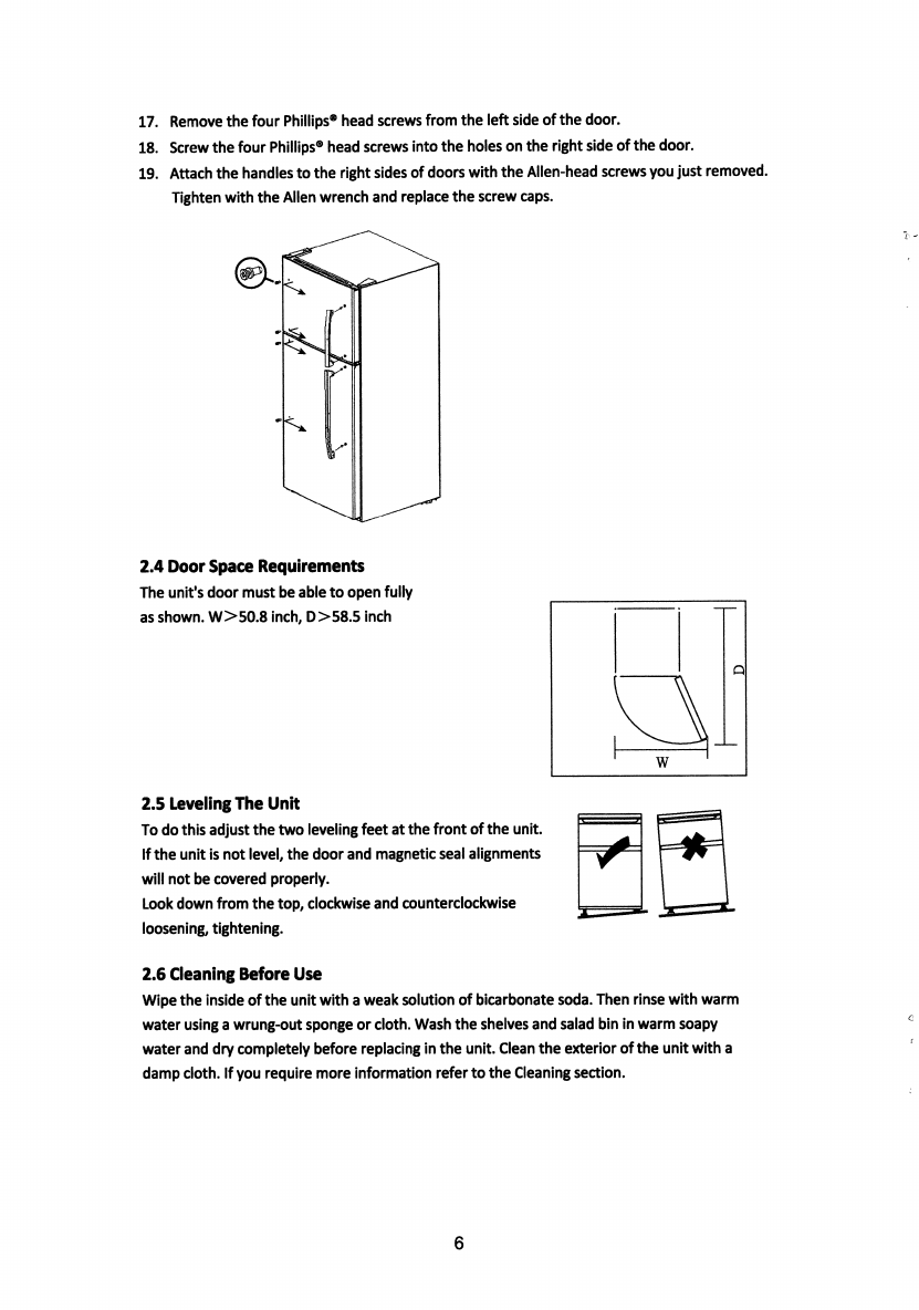
Remove
the
four
Phillips*
head
screws
from
the
left
side
of
the
door.
Screw
the
four
Phiiiips*
head
screws
into
the
holes
on
the
right
side
of
the
door.
Attach
the
handles
to
the
right
sides
of
doors
with
the
Allen-head
screws
you
just
removed.
Tighten
with
the
Aiien
wrench
and
repiace
the
screw
caps.
17.
18.
19.
2.4
Door
Space
Requirements
The
unit's
door
must
be
able
to
open
fully
as
shown.
W>50.8
inch,
D>58.5
inch
Q
2.5
Leveling
The
Unit
To
do
this
adjust
the
two
ieveiing
feet
at
the
front
of
the
unit.
If
the
unit
is
not
level,
the
door
and
magnetic
seal
alignments
wiil
not
be
covered
properly.
Look
down
from
the
top,
clockwise
and
counterclockwise
loosening,
tightening.
2.6
Cleaning
Before
Use
Wipe
the
inside
of
the
unit
with
a
weak
solution
of
bicarbonate
soda.
Then
rinse
with
warm
water
using
a
wrung-out
sponge
or
cloth.
Wash
the
shelves
and
salad
bin
in
warm
soapy
water
and
dry
completely
before
replacing
in
the
unit.
Clean
the
exterior
of
the
unit
with
a
damp
cloth.
If
you
require
more
information
refer
to
the
Cleaning
section.
6
2.7
Before
Using
Your
Unit
The
refrigerator
adopts
115V/60HZ
AC
power,
voltage
fluctuations
over
the
range
of
98
~
132V
will
cause
malfunction
or
even
damage.
Do
not
damage
the
power
cord
under
any
condition
so
as
to
ensure
safety
use,
do
not
use
when
the
power
cord
is
damaged
or
the
plug
is
worn.
Do
not
put
flammable,
explosive,
volatile
and
highly
corrosive
items
in
the
refrigerator
to
prevent
damages
to
the
product
or
fire
accidents.
Do
not
place
flammable
items
near
the
refrigerator
to
avoid
fires.
This
product
is
household
refrigerators
and
shall
be
only
suitable
for
the
storage
of
foods.
According
to
national
standards,
household
refrigerators
shall
not
be
used
for
other
purposes,
such
as
storage
of
blood,
drugs
or
biological
products.
Do
not
place
items
such
as
bottled
or
sealed
container
of
fluid
such
as
bottled
beers
and
beverages
in
the
freez
er
to
prevent
bursts
and
other
losses.
Before
placing
any
food
in
your
unit,
turn
it
on
and
wait
for
24
hours,
to
make
sure
it
is
working
properly
and
to
allow
it
time
to
fall
to
the
correct
temperature,
your
unit
should
not
be
overfilled.
Do
not
store
or
place
dry
ice
in
the
refrigerator.
t
m
V
A
Before
Plugging
in
You
must
check
that
you
have
a
socket
which
is
compatible
with
the
plug
supplied
with
the
unit.
Before
Turning
On
I
Do
not
turn
on
until
two
hours
after
moving
the
unit.
2.8
Interior
Accessories
Various
glass
or
plastic
storage
shelves
are
included
with
your
appliance
-
different
models
have
different
combinations.
You
should
always
slide
one
of
the
full
size
glass
storage
shelves
into
the
lowest
set
of
guides,
above
the
fruit
and
vegetable
containers,
and
keep
it
in
this
position.
To
do
this,
pull
the
storage
shelf
forward
until
it
can
be
swiveled
upwards
or
downwards
and
removed.
Please
do
the
same
in
reverse
to
insert
the
shelf
at
a
different
height.
In
order
to
make
the
full
use
of
the
volume
of
the
fresh
food
storage
compartment
and
frozen-food
storage
compartment,
the
user
can
remove
one
or
more
shelves,
drawers,
out
of
the
appliance,
according
to
your
daily
use.
2.9
Icemaker
Installation
(optional)
The
refrigerator
is
ready
for
ice
maker
installation,
if
you
need
ice
maker.
Please
select
the
type
of
IMISOOMD
MIDEA
IceMaker.
Remove
a
protective
cover
before
connecting
the
wire
of
the
ice
machine
in
the
box.
Tools
Required:
●
1/4
inch
copper
supply
line
with
shut
off
valve
●
1/4
inch
brass
compression
nut
and
ferrule
●
Freezer
shelf
of
your
model
does
not
have
one,
contact
your
dealer
to
order
one.
7
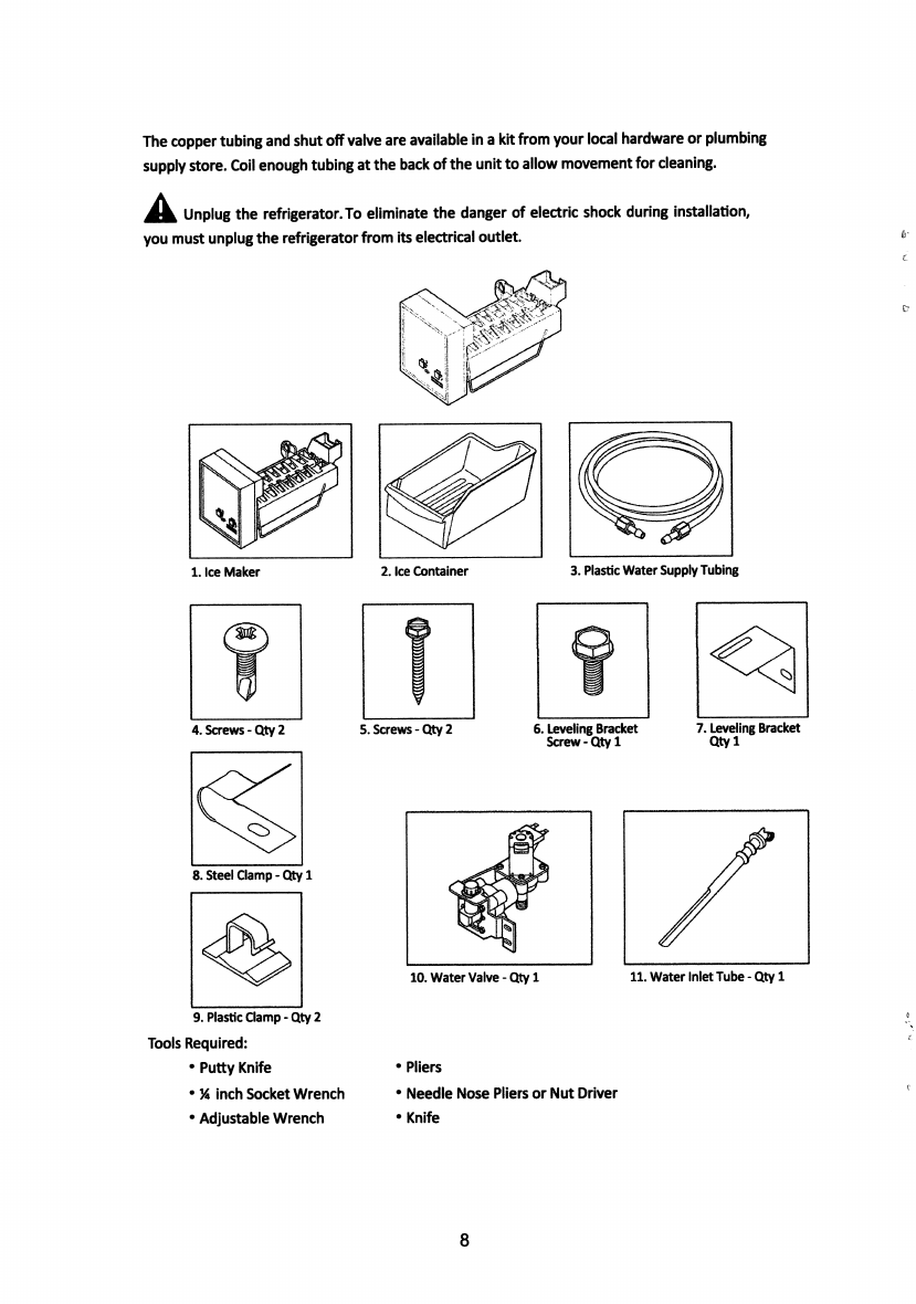
The
copper
tubing
and
shut
off
valve
are
available
In
a
kit
from
your
local
hardware
or
plumbing
supply
store.
Coil
enough
tubing
at
the
back
of
the
unit
to
aliow
movement
for
cleaning.
Unplug
the
refrigerator.To
eliminate
the
danger
of
electric
shock
during
installation,
you
must
unplug
the
refrigerator
from
its
electrical
outlet.
i'l
»l
3.
Plastic
Water
Supply
Tubing
1.
Ice
Maker
2.
Ice
Container
7.
Leveling
Bracket
Qtyl
6.
Leveling
Bracket
Screw
-
Qty
1
4.
Screws
-
Qty
2
5.
Screws-Qty
2
8.
Steel
Clamp
-
Qty
1
11.
Water
Inlet
Tube-Qtyl
10.
Water
Valve-Qtyl
9.
Plastic
Clamp
-
Qty
2
Tools
Required:
●
Putty
Knife
●
H
inch
Socket
Wrench
*
Adjustable
Wrench
●
Pliers
●
Needle
Nose
Pliers
or
Nut
Driver
●
Knife
8

1.
Unplug
refrigerator
from
wall
outlet.
2.
Remove
ice
tray
rack
from
freezer.
3.
The
frozen
shelf
moved
to
the
next
partition.
4.
Remove
plugs
from
inside
freezer
compartment
with
putty
knife.
O
\
5.
Peel
off
label
covering
ice
maker
hole.
RamowUbal
^
6.
With
needle
nose
pliers,
remove
foam
from
hole.
Remove
and
Discan}
■>
I
7.
Push
water
Inlet
tube
into
small
hole
on
back
of
refrigerator.
Rotate
while
inserting
tube
until
flat
surface
of
inlet
tube
is
tight
against
back
of
refrigerator.
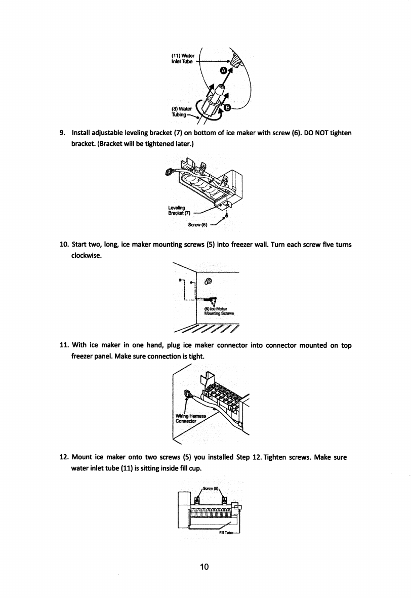
8.
Push
plastic
water
supply
tubing
(3)
into
water
inlet
tube
(11)
as
far
as
it
will
go
and
finger
tighten
nylon
compression
nut
onto
threaded
end
of
inlet
tube.
Tighten
another
one
half
turn
with
a
wrench.
DO
NOT
over
tighten.
9
(11)
Water
Inlet
Tube
(3)
Water
Tubing—.
9.
Install
adjustable
leveling
bracket
(7)
on
bottom
of
ice
maker
with
screw
(6).
DO
NOT
tighten
bracket.
(Bracket
wili
be
tightened
iater.)
Leveing
Bracket
(7)
i
Screw
(6)
10.
start
two,
iong,
ice
maker
mounting
screws
(5)
into
freezer
wail.
Turn
each
screw
five
turns
clockwise.
(Mice
Maker
Mountng
Screw6
11.
With
ice
maker
in
one
hand,
plug
ice
maker
connector
into
connector
mounted
on
top
freezer
panel.
Make
sure
connection
is
tight.
VWing
Harness
Connector
12.
Mount
ice
maker
onto
two
screws
(5)
you
instaiied
Step
12.
Tighten
screws.
Make
sure
water
inlet
tube
(11)
is
sitting
inside
fiii
cup.
t
10
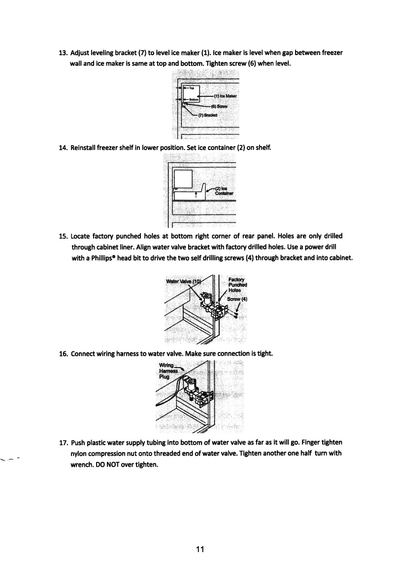
13.
Adjust
leveling
bracket
(7)
to
level
Ice
maker
(1).
Ice
maker
is
level
when
gap
between
freezer
wall
and
ice
maker
is
same
at
top
and
bottom.
Tighten
screw
(6)
when
levei.
»-T!»
■(1)ke
Maker
(6)
Screw
(7)
Bracket
14.
Reinstaii
freezer
sheif
in
lower
position.
Set
ice
container
(2)
on
shelf.
/l^(2)k»
Container
T
15.
Locate
factory
punched
holes
at
bottom
right
corner
of
rear
panel.
Holes
are
only
drilled
through
cabinet
liner.
Align
water
valve
bracket
with
factory
drilled
holes.
Use
a
power
drill
with
a
Phiiiips*
head
bit
to
drive
the
two
self
drilling
screws
(4)
through
bracket
and
into
cabinet.
Factory
Punched
Water
Valve
(II
/
Screw
(4)
16.
Connect
wiring
harness
to
water
valve.
Make
sure
connection
is
tight.
17.
Push
plastic
water
supply
tubing
into
bottom
of
water
valve
as
far
as
it
will
go.
Finger
tighten
nylon
compression
nut
onto
threaded
end
of
water
valve.
Tighten
another
one
half
turn
with
wrench.
DO
NOT
over
tighten.
11

Water
Valve
(10)
NybnNul
m
Plastic
Water
■TubtnB{3)
Tokematwr
PH
Tube
18.
Secure
plastic
water
tubing
to
rear
of
cabinet
with
two
piastic
clamps
(9).
NOTE:
Clean
back
of
cabinet
with
a
commercial
household
cleaner,
ammonia
or
alcohol
before
applying
clamps.
(9)
Plastic
aarap
2.10
Connecting
Ice
Maker
To
Water
Supply
Unplug
the
refrigerator.
To
eliminate
the
danger
of
electric
shock
during
installation,
you
must
unplug
the
refrigerator
from
its
electrical
outlet.
IMPORTANT:
Ensure
that
your
water
supply
line
connections
comply
with
all
local
plumbing
codes.
Before
Installing
The
Water
Supply
Line,
You
Will
Need:
●
Basic
tools:
adjustable
wrench,
flat
blade
screwdriver,
and
Phillips*
screwdriver.
●
Access
to
a
household
cold
water
line
with
water
pressure
between
20
and 120
psi.
●
A
water
supply
line
made
of
1/4
inch
(6.4
mm)
OD,
copper
tubing.
To
determine
the
length
of
copper
tubing
needed,
you
will
need
to
measure
the
distance
from
the
ice
maker
inlet
valve
at
the
back
of
the
refrigerator
to
your
cold
water
pipe.
Then
add
approximately
7
feet
(2.1
meters),
so
the
refrigerator
can
be
moved
out
for
cleaning.
●
A
shutoff
valve
to
connect
the
water
supply
line
to
your
household
water
system.
DO
NOT
use
a
self-piercing
type
shutoff
valve.
●
A
compression
nut
and
ferrule
(sleeve)
for
connecting
the
water
supply
line
to
the
ice
maker
inlet
valve.
NOTE:
Water
line
kit
number
5303917950,
available
from
your
appliance
dealer
at
additional
cost,
contains
25
Water
line
kit
number
5303917950,
available
from
your
appliance
dealer
at
additional
cost,
contains
25
compression
nuts,
(2)
ferrules/sleeves,
and
instructions
for
installing
a
water
supply
line.
To
Connect
Water
5upply
Line
To
Ice
Maker
Inlet
Valve:
1.
Disconnect
refrigerator
from
electric
power
supply.
2.
Place
end
of
water
supply
line
into
sink
or
bucket.
Turn
ON
water
supply
and
flush
supply
line
until
water
is
clear.
Turn
OFF
water
supply
at
shutoff
valve.
3.
Unscrew
plastic
cap
from
water
valve
inlet
and
discard
cap.
12
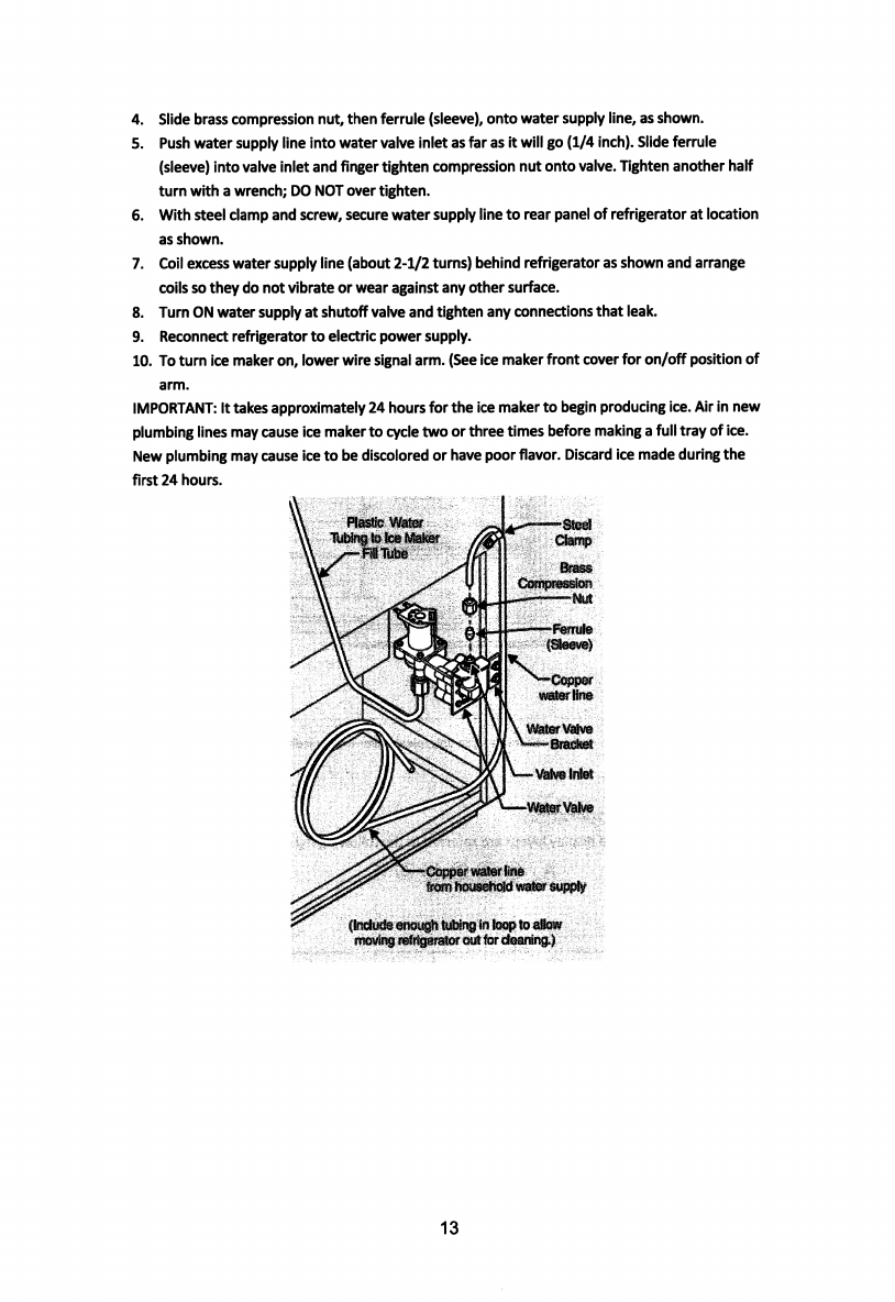
Slide
brass
compression
nut,
then
ferrule
(sleeve),
onto
water
supply
line,
as
shown.
Push
water
supply
line
into
water
valve
inlet
as
far
as
it
will
go
(1/4
Inch).
Slide
ferrule
(sleeve)
into
valve
inlet
and
finger
tighten
compression
nut
onto
valve.
Tighten
another
haif
turn
with
a
wrench;
DO
NOT
over
tighten.
With
steel
clamp
and
screw,
secure
water
supply
line
to
rear
panei
of
refrigerator
at
iocation
as
shown.
Coii
excess
water
supply
line
(about
2-1/2
turns)
behind
refrigerator
as
shown
and
arrange
coiis
so
they
do
not
vibrate
or
wear
against
any
other
surface.
Turn
ON
water
suppiy
at
shutoff
valve
and
tighten
any
connections
that
leak.
Reconnect
refrigerator
to
electric
power
suppiy.
To
turn
ice
maker
on,
iower
wire
signai
arm.
(See
ice
maker
front
cover
for
on/off
position
of
arm.
iMPORTANT:
It
takes
approximately
24
hours
for
the
ice
maker
to
begin
producing
ice.
Air
in
new
plumbing
lines
may
cause
ice
maker
to
cycie
two
or
three
times
before
making
a
full
tray
of
ice.
New
piumbing
may
cause
ice
to
be
discoiored
or
have
poor
fl
avor.
Discard
ice
made
during
the
first
24
hours.
4.
5.
6.
7.
8.
9.
10.
Plastic
Water
Tubing
to
Ice
Maker
^F*Tube
Steel
Clamp
Brass
Compression
Nut
-Ferrule
(Sleeve)
V
Copper
water
line
Water
Vdve
Bracket
Valve
Intel
■Water
Valve
Copper
water
line
from
household
water
supply
(Include
enough
tubing
in
loop
to
allow
rTKH/ing
refrigerator
out
to
r
deantrig.)
13

3.
PRODUCT
OVERVIEW
control
Salad
Cover
●All
images
in
this
Instruction
manual
are
for
Indication
only;
please
refer
to
your
individual
unit
for
details.
4.
OPERATION
HMI
and
keys
operation
The
keys
in
HMI
and
display
layout
are
referred
in
the
following
figure:
A
®
@(D
@(D
®
1
J
3 3
r”*T”
X
o
o
O
o
Q-
O
JlSUi!3&)
Temperatuiv
ConbX)l
\
SET
4.1
Key
A.
©Temperature
setting
button
of
refrigerator
compartment.
4.2
Display
Screen
®
Shift
1
@
Shift
2
@
Shift
3
®
Shift
4
®
Shift
5
®
Standby
indicator
14
5.
CLEANING
5.1
Defrosting
Auto-defrost
for
Frost-free
Refrigerator.
5.2
Cleaning
the
Interior
and
the
Exterior
of
the
Unit
●
Remove
all
the
shelves
and
the
salad
bin.
To
remove
the
salad
bin
first
remove
the
lower
door
shelf.
●
Wipe
the
inside
of
the
unit
with
a
weak
solution
of
bicarbonate
soda
and
then
rinse
with
warm
water
using
a
wrung-out
sponge
or
cloth.
Wipe
completely
dry
before
replacing
the
shelves
and
salad
bin.
●
Use
a
damp
cloth
to
clean
the
exterior,
and
then
wipe
with
a
standard
furniture
polish.
Make
sure
that
the
door
is
closed
to
avoid
the
polish
getting
on
the
magnetic
door
seal
or
inside
the
unit.
5.3
Cleaning
Tips
Condensation
may
appear
on
the
outside
of
the
unit.
This
may
be
due
to
a
change
in
room
temperature.
Wipe
of
any
moisture
residue.
If
the
problem
continues,
please
contact
a
qualified
technician
for
assistance.
6.
MAINTENANCE
6.1
Changing
The
Internal
Light
Setting
the
refrigerator
control
to
off
does
not
remove
power
to
the
light
circuit.
A
CAUTION:
Light
bulb
may
be
hot.
Light
bulb
parameter:
MAX
40W
1.
Unplug
the
refrigerator.
2.
The
bulb
is
located
at
the
top
of
the
compartment
near
the
opening.
3.
Replace
with
an
appliance
bulb
of
the
same
or
lower
wattage.
4.
Plug
the
refrigerator
back
in.
6.2
Care
When
Handling
/
Moving
Your
Unit
Hold
the
unit
around
its
sides
or
base
when
moving
it.
Under
no
circumstances
should
it
be
lifted
by
holding
the
edges
of
the
top
surface.
The
refrigerator
is
arranged
at
the
bottom
of
the
condenser,
be
careful
to
keep
the
bottom
dry,
used
in
the
handling
process.
Check
leveling
feet
before
moving.
6.3
Servicing
The
unit
should
be
serviced
by
an
authorized
engineer
and
only
genuine
spare
parts
should
be
used.
Under
no
circumstances
should
you
attempt
to
repair
the
unit
yourself.
Repairs
carried
out
by
inexperienced
persons
may
cause
injury
or
serious
malfunction.
Contact
a
qualified
technician.
6.4
Switching
Off
for
Long
Periods
of
Time
When
the
unit
is
not
in
use
for
a
long
period
of
time,
disconnect
it
from
the
main
power
supply,
empty
all
food
and
clean
the
appliance,
leaving
the
door
ajar
to
prevent
from
unpleasant
smells.
16
4.3
Display
●
Once
initially
powered
on,
the
display
screen
(including
the
key
light)
is
on
fuil
dispiay
for
3s,
and
then
operates
as
the
dispiayed
middle
shift.
●
Normai
operation
display
In
case
of
a
failure,
the
appropriate
LED
light
show
in
combination
the
faiiure
code
(in
recycling
display);
In
case
of
no
failures,
the
actual
operation
position
of
refrigerator
will
be
on
display.
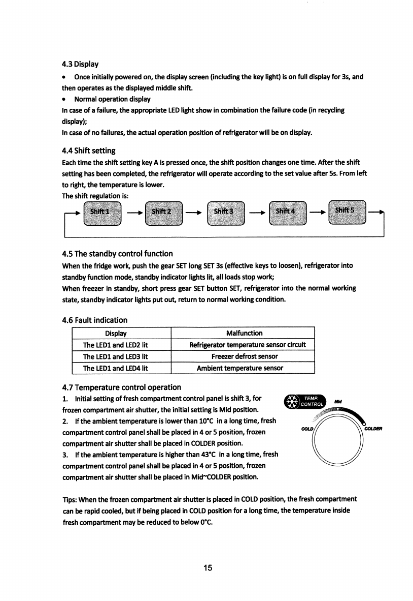
4.4
Shift
setting
Each
time
the
shift
setting
key
A
is
pressed
once,
the
shift
position
changes
one
time.
After
the
shift
setting
has
been
completed,
the
refrigerator
will
operate
according
to
the
set
value
after
5s.
From
left
to
right,
the
temperature
is
lower.
The
shift
regulation
is:
Shifts
Shift
4
Shift
1
Shift
2
Shifts
4.5
The
standby
control
function
When
the
fridge
work,
push
the
gear
SET
long
SET
3s
(effective
keys
to
loosen),
refrigerator
into
standby
function
mode,
standby
indicator
lights
lit,
all
loads
stop
work;
When
freezer
in
standby,
short
press
gear
SET
button
SET,
refrigerator
into
the
normal
working
state,
standby
indicator
lights
put
out,
return
to
normal
working
condition.
4.6
Fault
indication
Malfunction
Display
The
LEDl
and
LED2
lit
Refrigerator
temperature
sensor
circuit
The
LEDl
and
LEDS
lit
Freezer
defrost
sensor
The
LEDl
and
LED4
lit
Ambient
temperature
sensor
4.7
Temperature
control
operation
1.
Initial
setting
of
fresh
compartment
control
panel
is
shift
3,
for
frozen
compartment
air
shutter,
the
initial
setting
is
Mid
position.
2.
If
the
ambient
temperature
is
lower
than
10“C
in
a
long
time,
fresh
compartment
control
panel
shall
be
placed
in
4
or
5
position,
frozen
compartment
air
shutter
shall
be
placed
in
COLDER
position.
3.
If
the
ambient
temperature
is
higher
than
43°C
in
a
long
time,
fresh
compartment
control
panel
shall
be
placed
in
4
or
5
position,
frozen
compartment
air
shutter
shall
be
placed
in
Mid~COLDER
position.
\
TEMP.
inntJTtiai
Tips:
When
the
frozen
compartment
air
shutter
is
placed
in
COLD
position,
the
fresh
compartment
can
be
rapid
cooled,
but
if
being
placed
in
COLD
position
for
a
long
time,
the
temperature
inside
fresh
compartment
may
be
reduced
to
below
0”C.
15
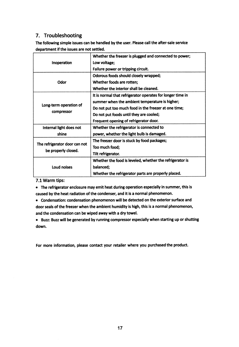
7.
Troubleshooting
The
following
simple
issues
can
be
handled
by
the
user.
Please
call
the
after-sale
service
department
if
the
issues
are
not
settled.
Whether
the
freezer
Is
plugged
and
connected
to
power;
Low
voltage;
Failure
power
or
tripping
circuit.
Inoperation
Odorous
fo
ods
should
closely
wrapped;
Whether
foods
are
rotten;
Whether
the
interior
shall
be
cleaned.
Odor
It
is
normal
that
refrigerator
operates
for
longer
time
in
summer
when
the
ambient
temperature
is
higher;
Do
not
put
too
much
food
in
the
freezer
at
one
time;
Do
not
put
fo
ods
until
they
are
cooled;
Frequent
opening
of
refrigerator
door.
Long-term
operation
of
compressor
Whether
the
refrigerator
is
connected
to
power,
whether
the
light
bulb
is
damaged.
Internal
light
does
not
shine
The
freezer
door
is
stuck
by
fo
od
packages;
Too
much
food;
Tilt
refrigerator.
The
refrigerator
door
can
not
be
properly
closed.
Whether
the
food
is
leveled,
whether
the
refrigerator
is
balanced;
Whether
the
refrigerator
parts
are
properly
placed.
Loud
noises
7.1
Warm
tips:
●
The
refrigerator
enclosure
may
emit
heat
during
operation
especially
in
summer,
this
is
caused
by
the
heat
radiation
of
the
condenser,
and
it
is
a
normal
phenomenon.
●
Condensation;
condensation
phenomenon
will
be
detected
on
the
exterior
surface
and
door
seals
of
the
freezer
when
the
ambient
humidity
is
high,
this
is
a
normal
phenomenon,
and
the
condensation
can
be
wiped
away
with
a
dry
towel.
●
Buzz:
Buzz
will
be
generated
by
running
compressor
especially
when
starting
up
or
shutting
down.
For
more
information,
please
contact
your
retailer
where
you
purchased
the
product.
17
This manual suits for next models
1
Table of contents
Other BEVOi Refrigerator manuals


