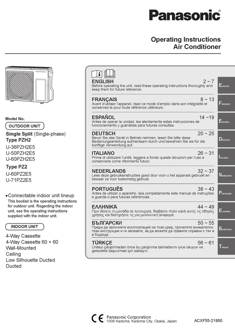
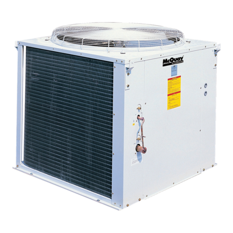
BGH BV-V28W/DHN1 User manual

Manual técnico
VRF Unidades Exteriores
Modelos:
BV-V28W/DHN1(At), BV-V36W/DHN1(At), BV-V42W/DHN1(At),
BV-V48W/DHN1(At), BV-V56W/DHN1(At).

1
Part 1 General Informaon............................................................................3
Part 2 Outdoor Unit Engineering Data ....................................................... 13
Part 3 System Design and Installaon........................................................ 69
Contents

2
VRF 50/60Hz

3
1 Indoor and Outdoor Unit Capacies........................................................ 4
2 External Appearance............................................................................... 5
3 Nomenclature......................................................................................... 6
4 Combinaon Rao .................................................................................. 7
5 Selecon Procedure ................................................................................ 8
General Informaon
Part 1

4
1Indoor and Outdoor Unit Capaci es
1.1 Indoor Units
Table 1-1.1: Indoor unit abbrevia on codes
Abbrevia on code Type
Q1 One-way Casse e
Q4C Compact Four-way Casse e
Q4 Four-way Casse e
T2 Medium Sta c Pressure Duct
G Wall-mounted
Table 1-1.2: Indoor unit capacity range
Capacity Capacity
index Q1 Q4C Q4 T2 G
kBtu/h kW HP
6 1.8 0.6 6 6 — — — —
7 2.2 0.8 7 7 7 — 7 7
9 2.8 1 9 9 9 9 9 9
12 3.6 1.25 12 12 12 12 12 12
15 4.5 1.6 15 15 15 15 15 15
18 5.6 2 18 18 — 18 18 18
24 7.1 2.5 24 24 — 24 24 24
28 8.0 3 28 — — 28 28 28
32 9.0 3.2 32 — — 32 32 32
36 10.0 3.6 36 — — 36 — —
40 11.2 4 40 — — 40 40 —
48 14.0 5 48 — — 48 48 —
56 16.0 6 56 — — — 56 —
Notes:
1. Atom series indoor units could connect to Atom series outdoor units.
1.2 Outdoor Units
Table 1-1.3: Outdoor unit capacity range
Capacity (kBtu/h)
Model Name
28 BV
36 BV
42 BV
48 BV
56 BV
Notes:
1. Atom series outdoor units could not be combined.
VRF 50/60Hz
-V28W/DHN1(At)
-V36W/DHN1(At)
-V42W/DHN1(At)
-V48W/DHN1(At)
-V56W/DHN1(At)

5
2External Appearance
2.1 Indoor Units
Table 1-2.1: Indoor unit appearance
One-way Cassee
Four-way Cassee
Q1
Q4
Compact Four-way Cassee
Wall-mounted
Q4C
G
Medium Stac Pressure Duct
T2
2.2 Outdoor Units
Table 1-2.2: Outdoor unit appearance
28 kBtu/h 36/42 kBtu/h 48/56 kBtu/h

6
3Nomenclature
3.1 Indoor Units
BV
-
D
09
Q4
/
N1
-
E
(At)
①
②
③
④
⑤
⑥
⑦
Legend
No. Code Remarks
1 BV BGH VRF
2 D VRF indoor unit
3 09 Capacity index (the capacity in kBtu/h)
4 Q4
Indoor unit type
Q1: One-way Cassee
Q4C: Compact Four-way Cassee
Q4: Four-way Cassee
T2: Medium Stac Pressure Duct
G: Wall Mounted
5 N1 Refrigerant type (N1: R410A)
6 E Design code
7 At Atom series
3.2 Outdoor Units
BV
-
V
28
W
/
D
H
N1
(At)
①
②
③
④
⑤
⑥
⑦
⑧
Legend
No. Code Remarks
1 BV BGH VRF
2 V All DC inverter
3 28 Capacity index (the capacity in kBtu/h)
4 W VRF outdoor unit
5 D DC inverter compressor
6 H
Power supply
Omit: 1 phase, 220-240V, 50Hz
H: 1 phase, 220-240V, 50/60Hz
7 N1 Refrigerant type (N1: R410A)
8 At Atom series
VRF 50/60Hz

7
4Combinaon Rao
Table 1-4.1: Indoor and outdoor unit combinaon rao limitaons
Type Minimum combinaon rao Maximum combinaon rao
Atom Series outdoor units
45%
130%
Table 1-4.2: Combinaons of Indoor and outdoor units
Outdoor unit capacity
Sum of capacity indexes of
connected indoor units (standard
indoor units only)
Number of connected
indoor units
kBtu/h
Capacity
index
28 28 12.6 to 36.4 1-4
36 36 16.2 to 46.8 1-6
42 42 18.9 to 54.6 1-7
48 48 21.6 to 62.4 1-8
56 56 25.2 to 72.8 1-9
Combinaon rao = Sum of capacity indexes of the indoor units
Capacity index of the outdoor unit

8
5Selecon Procedure
5.1 Procedure
Step 1: Establish designcondions
Step 2: Select indoor units
Step 3: Select outdoor unit
Notes:
1. If the indoor design temperature falls between two temperatures listed in the indoor unit's capacity table, calculate the corrected capacity by interpolaon.
If the indoor unit selecon is to be based on total heat load and sensible heat load, select indoor units which sasfy not only the total heat load requirements
of each room but also the sensible heat load requirements of each room. As with total heat capacity, the sensible heat capacity of indoor units should be
corrected for indoor temperature, interpolang where necessary. For the indoor unit capacity tables, refer to the indoor unit technical manuals.
Yes
Design temperature and humidity (indoor and outdoor)
Required heat load of each room
System peak load
Piping length, level differences
Indoor unit specificaons (type and quanty)
Decide indoor unit safety factor
Select indoor unit models ensuring that:
Indoor unit capacity corrected for indoor air temperature WB1≥Required heat load × Indoor unit safety factor
Determine required total heat load on the outdoor unit
Use the sum of the peak load of each room Use the system peak load
Provisionally select outdoor unit capacity based on combinaon rao limitaons
Confirm that the number of indoor units connected to the outdoor unit is within limitaon
Correct cooling and heang capacies of the outdoor unit for the following items:
Outdoor air temperature / Indoor air temperature WB / Combinaon rao / Piping length, level difference
/ Piping heat loss / Frost accumulaon (for heang capacity only)
Is corrected outdoor unit capacity ≥Required total heat load on outdoor unit?
VRF system selecon is complete
No
VRF 50/60Hz

9
5.2 Example
The following is a selecon example based on total heat load for cooling.
Figure 1-5.1: Room plan
Room A
Room B
Room C
Room D
Step 1: Establish design condions
•Indoor air temperature 25°C DB, 18°C WB; outdoor air temperature 33°C DB.
•Determine peak load of each room and system peak load. As shown in Table 1-5.1, the system peak load is 10.5kW.
Table 1-5.1: Required heat load of each room (kW)
Time Room A Room B Room C Room D Total
9:00 2.5 1.6 1.6 1.6 7.3
12:00 3.2 2.4 2.4 2.4 10.4
14:00 3.1 2.4 2.4 2.6 10.5
16:00 3.1 2.3 2.3 2.3 10
•The maximum piping lengths and level differences in this example are as given in Figure 1-5.2.
Figure 1-5.2: System diagram
•Indoor unit type for all rooms: Medium Stac Pressure Duct (T2).
Step 2: Select indoor units
•In this example, a safety factor is not used (i.e. the safety factor is 1).
•Select indoor unit models using the medium stac pressure duct cooling capacity table. Each indoor unit's corrected
capacity needs to be greater than or equal to the peak load of the relevant room. The selected indoor units are shown
in Table 1-5.3.
Equivalent length of piping 50m
Lev
el
differenc
e
20
m
Outdoor
Unit
Indoor
Unit
Indoor
Unit
Indoor
Unit
Indoor
Unit

10
Table 1-5.2: Extract from medium stac pressure duct (T2) cooling capacity table
Model
Capacity
index
Indoor air temperature
14°C WB 16°C WB 18°C WB 19°C WB 20°C WB 22°C WB 24°C WB
20°C DB 23°C DB 26°C DB 27°C DB 28°C DB 30°C DB 32°C DB
kBtu/h kW×10
TC SHC TC SHC TC SHC TC SHC TC SHC TC SHC TC SHC
T2
7 22 1.5 1.4 1.8 1.5 2.1 1.6 2.2 1.6 2.3 1.7 2.4 1.5 2.4 1.5
9 28 1.9 1.7 2.3 1.9 2.6 2.1 2.8 2.1 3.0 2.1 3.1 2.0 3.1 1.9
12 36 2.5 2.1 2.9 2.3 3.4 2.5 3.6 2.6 3.8 2.7 4.2 2.8 3.9 2.3
15 45 3.1 2.6 3.7 2.8 4.2 3.1 4.5 3.2 4.8 3.2 4.9 3.1 5.1 2.9
18 56 3.9 3.0 4.6 3.3 5.3 3.6 5.6 3.7 5.9 3.8 6.2 3.7 6.2 3.4
24 71 4.9 3.9 5.8 4.3 6.7 4.7 7.1 4.9 7.5 4.8 7.8 4.6 7.8 4.3
28 80 5.5 4.4 6.6 4.9 7.5 5.3 8.0 5.5 8.4 5.5 8.8 5.2 8.8 4.8
32 90 6.2 5.3 7.3 5.8 8.4 6.3 9.0 6.4 9.6 6.5 9.9 6.1 9.9 5.7
40 112 7.7 6.4 9.1 7.1 10.5 7.7 11.2 7.8 11.9 8.1 12.5 7.8 12.5 7.4
48 140 9.7 7.8 11.3 8.6 13.2 9.6 14.0 9.8 14.8 9.8 15.7 9.7 15.4 8.8
Abbreviaons:
TC: Total capacity (kW); SHC: Sensible heat capacity (kW)
Table 1-5.3: Selected indoor units
Room A Room B Room C Room D
Peak heat load (kW) 3.1 2.4 2.4 2.6
Selected indoor unit BV-D12T2/N1-DA5(At) BV-D09T2/N1-DA5(At) BV-D09T2/N1-DA5(At) BV-D09T2/N1-DA5(At)
Corrected TC (kW) 3.6 2.8 2.8 2.8
Step 3: Select outdoor unit
•Determine the required total heat load from the indoor units tothe outdoor unit based on either the sum of the peak
loads of each room or the system peak load. In this example, it is determined based on the system peak load. Therefore,
the required heat load is 10.5kW.
•Provisionally select an outdoor unit using the sum of the capacity indexes (CIs) of the selected indoor units (as shown
in Table 1-5.4), ensuring that the combinaon rao is between 50% and 130%. Refer toTable 1-5.5. As the sum of CIs
of the indoor units is 120, all outdoor units are potenally suitable except 8kW. Start from the smaller, which is the
10kW unit.
Table 1-5.4: Sum of indoor unit capacity indexes
Model Capacity Index No. of units
BV-D12T2/N1-DA5(At) 36 1
BV-D09T2/N1-DA5(At) 28 3
Sum of CIs 120
Table 1-5.5: Combinaons of Indoor and outdoor units
Outdoor unit capacity
Sum of capacity indexes of
connected indoor units
(standard indoor units only)
kBtu/h
Capacity
index
28 28 14 to36.4
36 36 18 to46.8
42 42 21 to54.6
48 48 24 to62.4
56 56 28 to72.8
VRF 50/60Hz

11
•The number of connected indoor units is 4 and the maximum number of connected indoor units on the 10kW outdoor
unit is 6, so the number of connected indoor units is within the limitaon.
•Calculate the corrected capacity of the outdoor unit:
a) The sum of the indoor unit CIs is 120 and the CI of the 10kW outdoor unit is 100, so the combinaon rao is 120 /
100 = 120%.
b) Using the outdoor unit’s cooling capacity table, interpolate to obtain the capacity (“B”) corrected for outdoor air
temperature, indoor air temperature, and combinaon rao. Refer to Tables 1-5.6 and 1-5.7.
Table 1-5.6: Extract from Table 2-7.2 BV-V36W/DHN1(At)
cooling capacity
Table 1-5.7: Cooling capacity calculated by interpolaon
CR
Outdoor
air
temp.
(°C DB)
Indoor air temp.
(°C DB / °C WB)
CR
Outdoor
air
temp.
(°C DB)
Indoor air temp.
(°C DB / °C WB)
25.8 / 18.0
25.8 / 18.0
TC PI
TC PI
kW kW
kW kW
120%
31
10.56
2.50
120%
33
10.44
2.59
33
10.44
2.59
35 10.22 2.68
B =10.44
110%
31
10.33 2.44
110%33 10.22 2.57
33 10.22 2.57
35 10.00 2.66
c) Find the correcon factor for piping length and level difference (“K1”)
Figure 1-5.3: Atom rate of change in cooling capacity
d) Calculate the corrected capacity of BV-V36W/DHN1(At) (“C”) by using K1:
C = B × K1 = 10.44 × 0.968 =10.1kW
•The corrected capacity 10.1 kW is lower than required total heat load 10.5kW, so selecon is not complete. Step 3
should be repeated from the point where the outdoor unit capacity is provisionally selected.
Repeat Step 3: Select outdoor unit
•Determine the required total heat load from the indoor units to the outdoor unit based on either the sum of the peak
loads of each room or the system peak load. In this example, it is determined based on the system peak load. Therefore,

12
the required heat load is 10.5kW.
•Provisionally select an outdoor unit using the sum of the capacity indexes (CIs) of the selected indoor units (as shown
in Table 1-5.5), ensuring that the combinaon rao is between 50% and 130%. Refer to Table 1-5.6. As the sum of CIs
of the indoor units is 120. For the 10kW unit is not suitable, try to select 12kW unit.
•The number of connected indoor units is 4 and the maximum number of connected indoor units on the 12kW outdoor
unit is 7, so the number of connected indoor units is within the limitaon.
•Calculate the corrected capacity of the outdoor unit:
a) The sum of the indoor unit CIs is 120 and the CI of the 12kW outdoor unit is 120, so the combinaon rao is 120 /
120 = 100%.
b) Using the outdoor unit’s cooling capacity table, interpolate to obtain the capacity (“B”) corrected for outdoor air
temperature, indoor air temperature, and combinaon rao. Refer to Tables 1-5.8 and 1-5.9.
Table 1-5.8: Extract from Table 2-7.3 BV-V42W/DHN1(At)
cooling capacity
Table 1-5.9: Cooling capacity calculated by interpolaon
CR
Outdoor
air
temp.
(°C DB)
Indoor air temp.
(°C DB / °C WB)
CR
Outdoor
air
temp.
(°C DB)
Indoor air temp.
(°C DB / °C WB)
25.8 / 18.0
25.8 / 18.0
TC
PI
TC
PI
kW
kW
kW
kW
100%
31 11.2 2.46
100%
33 11.2 2.63
33 11.2 2.76
35 11.2 2.80
B = 11.2
90%
31 10.1 2.11
90%33 10.1 2.26
33 10.1 2.37
35 10.1 2.40
c) Find the correcon factor for piping length and level difference (“K1”)
Figure 1-5.4: Atom rate of change in cooling capacity
d) Calculate the corrected capacity of BV-V42W/DHN1(At) (“C”) by using K1:
C = B × K1 = 11.2 × 0.968 =10.84kW
•The corrected capacity 10.84 kW is larger than required total heat load 10.5kW, so selecon is complete.
VRF 50/60Hz

13
1 Specificaons ........................................................................................ 14
2 Dimensions ........................................................................................... 15
3 Installaon Space Requirements ........................................................... 17
4 Piping Diagrams .................................................................................... 18
5 Wiring Diagrams.................................................................................... 20
6 Electrical Characteriscs........................................................................ 23
7 Capacity Tables...................................................................................... 24
8 Operang Limits.................................................................................... 65
9 Sound Levels ......................................................................................... 66
10 Accessories.......................................................................................... 68
Outdoor Unit
Engineering Data
Part 2

14
1Specications
BV-V28W/DHN1(At) / BV-V36W/DHN1(At) / BV-V42W/DHN1(At)
Table 2-1.1: 28/36/42 modelspecications
Model BV-V28W/DHN1(At) BV-V36W/DHN1(At) BV-V42W/DHN1(At)
Power supply V-Ph-Hz 220-240/1/ 50(60)
Cooling1
Capacity kBtu/h 28 36 42
kW 8 10 12
Input kW 2.1 2.66 3.31
EER kW/ KW 3.81 3.76 3.63
Heang2
Capacity
kBtu/h 32 42 48
kW 9 12 14
Input kW 2.04 3.15 3.64
COP kW/ kW 4.41 3.81 3.85
Connectable
indoor unit
Total capacity 45~130% of outdoor unit capacity
Quanty 1~4 1~6 1~7
Compressor
Type DC inverter DC inverter DC inverter
Quanty 1 1 1
Oil type RB74AF RB74AF RB74AF
Fan
Motor type DC motor DC motor DC motor
Quanty 1 1 1
Output W 80 170 170
Outdoor air flow m3/h 3700 5200 5000
Sound pressure level3 dB(A) 54 54 56
Net dimensions (W×H×D)4mm 910 x 712 x 426 950 x 840 x 440 950 x 840 x 440
Packed dimensions (W×H×D) mm 1045 x 810 x 485 1025 x950 x 510 1025 x950 x 510
Net weight kg 53 71.5 83
Gross weight kg 57.5 81 92
Refrigerant
Type R410A R410A R410A
Factory charge g 2200 2350 3000
Throle type Electronic expansion valve
Pipe connecons
Liquid pipe mm Ф9.53 Ф9.53 Ф9.53
Gas pipe mm Ф15.9 Ф15.9 Ф15.9
Ambient Temp.
operaon range
Cooling oC -5~55
Heang oC -15~27
Notes:
1. The cooling condions: indoor temp: 27 oC DB (80.6 oF), 19 oC WB (66.2 oF) outdoor temp: 35 oC DB (95 oF) equivalent pipe length: 5m drop length: 0m.
2. The heang condions: indoor temp: 20 oC DB (68 oF), 15 oC WB (44.6 oF) outdoor temp.: 7 oC DB (42.8 oF) equivalent pipe length: 5m drop length: 0m.
3. Sound level: Anechoic chamber conversion value, measured at a point 1 m in front of the unit at a height of 1m for 28/26 model, 1.2m for 42 model. During
actual operaon, these values are normally somewhat higher as a result of ambient condions.
4. Diameters given are those of the unit's stop valves.
5. The above data may be changed without noce for future improvement on quality and performance.
VRF 50/60Hz

15
BV-V48W/DHN1(At) / BV -V56W/DHN1(At)
Table 2-1.2: 48/52 model specificaons
Model BV-V48W/DHN1(At) BV-V56W/DHN1(At)
Power supply V-Ph-Hz 220-240/1/ 50(60)
Cooling1
Capacity
kBtu/h 48 56
kW 14 15.5
Input kW 3.97 4.87
EER kW/ KW 3.53 3.18
Heang2
Capacity
kBtu/h 56 63
kW 16 18
Input kW 3.98 4.82
COP kW/ kW 4.02 3.73
Connectable
indoor unit
Total capacity 45~130% of outdoor unit capacity
Quanty 1~8 1~9
Compressor
Type DC inverter DC inverter
Quanty 1 1
Oil type RB74AF RB74AF
Fan
Motor type DC motor DC motor
Quanty 1 1
Output W 170 170
Outdoor air flow m3/h 5400 5200
Sound pressure level3dB(A) 56 56
Net dimensions (W×H×D)4mm 1040 x 865 x 523 1040 x 865 x 523
Packed dimensions (W×H×D) mm 1120 x 980 x 560 1120 x 980 x 560
Net weight kg 90.4 94.4
Gross weight kg 100.4 104.4
Refrigerant
Type R410A R410A
Factory charge g 3400 3800
Throle type Electronic expansion valve
Pipe connecons
Liquid pipe mm Ф9.53 Ф9.53
Gas pipe mm Ф15.9 Ф19.1
Ambient Temp.
operaon range
Cooling oC -5~55
Heang oC -15~27
Notes:
1. The cooling condions: indoor temp: 27 oC DB (80.6 oF), 19 oC WB (66.2 oF) outdoor temp: 35 oC DB (95 oF) equivalent pipe length: 5m drop length: 0m.
2. The heang condions: indoor temp: 20 oC DB (68 oF), 15 oC WB (44.6 oF) outdoor temp.: 7 oC DB (42.8 oF) equivalent pipe length: 5m drop length: 0m.
3. Sound level: Anechoic chamber conversion value, measured at a point 1 m in front of the unit at a height of 1m for 28/26 model, 1.2m for 42 model. During
actual operaon, these values are normally somewhat higher as a result of ambient condions.
4. Diameters given are those of the unit's stop valves.
5. The above data may be changed without noce for future improvement on quality and performance.

16
2Dimensions (unit: mm)
Figure 2-2.1: 28 model front view dimensions Figure 2-2.2: 28 model top view dimensions
Figure 2-2.3: 28/36 model front view Dimensions Figure 2-2.4: 28/36 model front top Dimensions
Figure 2-2.5: 48/56 model front view Dimensions Figure 2-2.6: 48/56 model front top Dimensions
Model A B C D E F G H I
28 910 982 390 345 120 663 712 375 426
36/42 950 / 406 360 175 590 840 390 440
48/56
1040
1053
452
410
191
656
865
463
523

17
3Installaon Space Requirements
Figure 2-3.1: Single unit installaon top view (unit: mm) Figure 2-3.2: Single unit installaon side view (unit: mm)
Figure 2-3.3: Mulple unit installaon top view (unit: mm)
Figure 2-3.4: Mulple unit installaon side view (unit: mm)

18
4Piping Diagrams
Figure 2-4.1: 28 model Piping diagram
Figure 2-4.2: 36/42 model Piping diagram
VRF 50/60Hz

19
Figure2-4.3: 48/56 modelPiping diagram
Key components:
1. Oil separator:
Separates oil from gas refrigerant pumped out of the compressor and quickly returns it to the compressor. Separaon
efficiency is up to 99%.
2. Gas-liquid separator:
Stores liquid refrigerant and oil to protect compressor from liquid hammering.
3. Electronic expansion valve (EXV):
Controls refrigerant flow and reduces refrigerant pressure.
4. Four-way valve(ST1):
Controls refrigerant flow direcon. Closed in cooling mode and open in heang mode. When closed, the heat exchanger
funcons as a condenser; when open, the heat exchanger funcons as an evaporator.
5. High and low pressure switches:
Regulate system pressure. When system pressure rises above the upper limit or falls below the lower limit, the high or
low pressure switches turn off, stopping the compressor. Aer 5 minutes, the compressor restarts.
Accumulator
Other manuals for BV-V28W/DHN1
1
This manual suits for next models
8
Table of contents
Other BGH Air Conditioner manuals
Popular Air Conditioner manuals by other brands
Midea
Midea PD series manual
Heiko
Heiko JZ026-B1 installation manual
Daikin
Daikin Comfort Flex CLIV Series Installation, operation and maintenance manual

Hitachi
Hitachi RAS-70YHA1 instruction manual
Frigidaire
Frigidaire FFMS121CQ10 installation manual
Panasonic
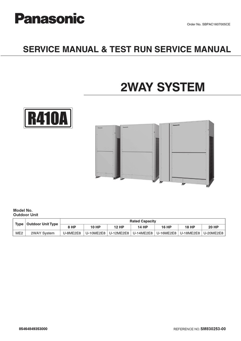
Panasonic U-8ME2E8 Service Manual & Test Run Service Manual


