Inficon PEG100 User manual

Operating Manual
Incl. EU Declaration of Conformity
tina14e1-a (2017-12) 1
Penning Gauge
PEG100

2tina14e1-a (2017-12) PEG100.om
In all communications with INFICON, please specify the information on the product
nameplate. For convenient reference copy that information into the space provided
below.
This document applies to products with part numbers
351-000 (PEG100, DN 25 ISO-KF)
351-002 (PEG100, DN 40 CF-F)
The part number (No:) can be taken from the product nameplate.
We reserve the right to make technical changes without prior notice.
All dimensions in mm.
The references to diagrams, e.g. (4/1), consist of the fig. no. and the item no. in
that order.
The Penning Gauge PEG100 has been designed for vacuum measurement of in
the pressure range of 1×10⁻⁹ to 1×10⁻² mbar.
The Penning Gauge PEG100 is a compact active pressure converter housing a
Penning measurement system as well as the corresponding operating electronics.
They have been developed specifically for integration into vacuum systems and
offer a measurement range from 1×10⁻⁹ to 1×10⁻² mbar.
The gauge is connected directly to the vacuum system through its DN 25 KF or
DN 40 CF flange.
The electrical connection is provided through a screened 8-pin FCC 68 connector.
Unpack the PEG100 immediately after delivery, even if it is to be installed at a later
date.
Examine the packaging for any external damage. Completely remove all packaging
materials.
Retain the shipping container and the packaging materials in the event of com-
plaints about damage.
Check that the PEG100 is complete and carefully examine the gauges visually.
If any damage is discovered, report it immediately to the forwarding agent and in-
surer. If the damaged part has to be replaced, please get in touch with the orders
department.
Product Identification
Validity
Intended Use
Description
Unpacking and Checking

tina14e1-a (2017-12) PEG100.om 3
Based on a supply voltage of 24 V the PEG100 generates the internal supply vol-
tages required for operation of the integrated Penning measurement system. The
PEG100 supplies a logarithmic representation of the vacuum pressure by way of a
voltage signal which ranges from 0.66 V to 10 V. Moreover, the high tension
generated in the PEG100 can be switched on and off by applying an external con-
trol voltage or by connecting an external switch.
When the gas discharge in the Penning measurement system is ignited, the oper-
ating voltage is raised to 2.8 kV. After successful ignition, this voltage then drops to
1.6 kV thereby increasing the useful service life of the Penning measurement
system.
A status output indicates the two possible conditions of the Penning measurement
system:
1. not ignited (including high tension OFF) and
2. ignited (and pressure > 3×10⁻⁹ mbar).
A much improved ignition characteristic in the high vacuum range has been ob-
tained through the special design for the electrodes in the measurement system.
•Penning Gauge
•Replacement cathode plate of titanium
•Replacement ceramics disc
•Operating Manuals
Design and Function
Scope of Delivery

4tina14e1-a (2017-12) PEG100.om
Contents
Product Identification 2
Validity 2
Intended Use 2
Description 2
Unpacking and Checking 2
Design and Function 3
Scope of Delivery 3
1Safety 5
1.1 Symbols Used 5
1.2 Personnel Qualifications 5
1.3 General Safety Instructions 5
1.4 Liability and Warranty 5
2Technical Data 6
3Installation 8
3.1 Vacuum Connection 8
3.2 Electrical Connection 8
3.2.1 Power Supply 10
3.2.2 Switching on the High Tension 10
3.2.3 Measurement Signal Output 10
3.2.4 Status Output 11
3.2.5 Identification 11
4Operation 12
4.1 Operation 12
4.2 Measurement System Status Indication 13
4.3 Degassing 13
4Maintenance 14
5.1 The Electronics Assembly 14
5.2 Cleaning the Sensor 14
5.2.1 Detaching the Electronics Assembly 14
5.2.2 Disassembly of the Sensor 15
5.2.3 Cleaning the Individual Parts 15
5.2.4 Assembly of the Sensor 15
5.2.5 Assembly of the Electronics Assembly 16
6Troubleshooting 16
7Wearing Parts and Original Spare Parts 17
9Returning the Product 18
10 Disposal 18
Appendix 19
A: Output Voltage vs. Pressure 19
B: Examples for Connecting 20
EU Declaration of Conformity 21
For cross-references within this document, the symbol (→XY) is used.
tina14e1-a (2017-12) PEG100.om 5
1 Safety
DANGER
Information on preventing any kind of physical injury.
WARNING
Information on preventing extensive equipment and environmental damage.
Caution
Information on correct handling or use. Disregard can lead to malfunctions or
minor equipment damage.
Notice
Skilled personnel
All work described in this document may only be carried out by persons who have
suitable technical training and the necessary experience or who have been
instructed
•Adhere to the applicable regulations and take the necessary precautions for the
process media used.
Consider possible reactions with the product materials (→6).
•Adhere to the applicable regulations and take the necessary precautions for all
work you are going to do and consider the safety instructions in this document.
•Before beginning to work, find out whether any vacuum components are conta-
minated. Adhere to the relevant regulations and take the necessary precautions
when handling contaminated parts.
Communicate the safety instructions to all other users.
INFICON assumes no liability and the warranty is rendered null and void if the end-
user or third parties
•disregard the information in this document
•use the product in a non-conforming manner
•make any kind of interventions (modifications, alterations etc.) on the product
•use the product with accessories not listed in the corresponding product docu-
mentation.
1.1 Symbols Used
Symbols for residual risks
1.2 Personnel Qualifications
1.3 General Safety
Instructions
1.4 Liability and Warranty

6tina14e1-a (2017-12) PEG100.om
2 Technical Data
Measurement range 1×10⁻⁹ to 1×10⁻² mbar
Measurement uncertainty in the range from 1×10⁻⁸ to 1×10⁻⁴ mbar
Deviation from the characteristic ±30 % of the displayed value
Average temperature coefficient of the
output span
<0,5 % / K of the displayed value
Reproducibility <4 % of the displayed value
Measurement principle Cold cathode ionization according to
Penning
Supply voltage 14.5 to 36 V (dc) typ. 24 V (dc),
2 Vss
Power consumption <2 W
Protection IP 40
Flammability UL 94 - V 2
Status displays
Operation (POWER) orange LED
Ready to measure (ignited) READY green LED
Measurement system detachable
Vacuum connection DN 25 KF or DN 40 CF
Degassing temperature see Section 4.3
Internal volume 21 cm3approx.
Materials in contact with the medium stainless steel; CrNi; AL2O3 ceramics;
NiFe; Ni; titanium
Overpressure tolerance 10 bar abs.
(The limits for the flange connections must be observed)
Operating voltage 1.6 kV (current limited to <0,5 mA)
Ignition voltage 2.8 kV (current limited to < 0,5 mA)
Signal output 0 to 10,6 V
Permissible load resistance Ra 10 k
Measurement signal 0,66 to 10,0 V
logarithmic 1.333 V / per decade
Status signal (not ignited) 0.4 V
Input resistance RE: 10 kapprox.
High voltage cut-in with negative logic at
pin 7:
High voltage ON at U <2.5 V
High voltage OFF at U >4 V
or
High voltage cut-in with positive logic at
pin 8:
High voltage ON at U >12 V
High voltage OFF at U <7 V
(for this refer also to figure 3 and section 3.2.2)
Ready to measure High level (13.5 to 35 V, max.
50 mA)
Error (not ignited, HV off) 0 V
For this refer also to section 3.2.4.
General Data
Measurement System
Signal Output
Control Inputs
Status Output

tina14e1-a (2017-12) PEG100.om 7
Fig. 1 Dimensional drawing
Weight 500 g approx
Storage temperature range –20 °C to +70 °C
Climatic rating KWF to DIN 40040
Operating temperature range 10 °C to 50 °C
Max. rel. humidity of the ambient air (on 30
days per year, non-condensing)
70 %1) or 95 %2)
1) usable measurement range 10-2 to 10-9 mbar
2) usable measurement range 10-2 to 10-7 mbar
Dimensions [mm], Weight
Ambient Conditions

8tina14e1-a (2017-12) PEG100.om
3 Installation
Please check by referring to the technical data whether or not your gauge is
suitable for your application.
The Penning Gauge PEG100 should preferably be mounted flange down. Inclined
installation is possible but the horizontal orientation must not be exceeded.
Flange up installation is not permissible because under such circumstances con-
densate may collect in the PEG100. This will either adversely affect the measure-
ments, or the sensor itself may possibly be damaged.
The Penning Gauge is equipped with a DN 25 KF or a DN 40 CF connection
flange. The DN 25 KF flange is used to connect the gauge to the mating connec-
tion flange on a vacuum system with the aid of a centering ring and a clamping
ring.
The cathode plate (7/5) also acts as a baffle.
The supply voltage and the high voltage switching signal as well as the measure-
ment voltage signal are carried through the 8-way FCC 68 socket.
Fig. 2 Connection socket
The pinout is given in Fig. 2.
Pin Signal Designation on
the rear
Pin 1 Supply voltage 14,5 V to 36 V (dc) +24 V (dc)
Pin 2 0 V supply; used as the ground reference for the
supply and control signal voltages
COMMON
Pin 3 Pressure dependent logarithmic signal output SIGN 0 - 10 V
Pin 4 Gauge identification (100 k) IDENT
Pin 5 Signal ground (use only for the pressure signal) SIGN COM
Pin 6 Status (ready to measure) STATUS
Pin 7 High tension "ON / OFF" (control input); Low active HV ON (L)
Pin 8 High tension "ON / OFF" (control input); High active HV ON (H)
Signal ground (Pin 5) and power supply ground (Pin 2) are internally linked. For
this also refer to the block diagram of Fig. 3.
3.1 Vacuum Connection
3.2 Electrical Connection

tina14e1-a (2017-12) PEG100.om 9
Two examples of how to connect the PEG100 are given in Annex B.
Fig. 3 Block diagram

10 tina14e1-a (2017-12) PEG100.om
DANGER
The Penning Gauge PEG100 may only be connected to supply units
or measuring instruments which meet the requirements of mains
isolated extra-low voltages (PELV) and VDE 0100.
The PEG100 is capable of operating off supply voltages ranging from 14.5 V to
36 V. A supply voltage of 24 V (dc) is recommended.
The power supply must be connected to Pin 1 (+) and Pin 2 (power supply ground).
The high voltage may be switched on either through Pin 7 using negative logic or
Pin 8 using positive logic.
In each case Pin 2 must be used as the reference potential.
Pin 7 switches the high voltage on when
•contact is established with Pin 2 or
•a voltage of less than 2.5 V is present with reference to Pin 2.
Pin 7 switches the high voltage off when
•there is no contact with Pin 2 (open input) or
•a voltage greater than 4 V is present with reference to Pin 2.
Pin 8 switches the high voltage on when
•contact is established with Pin 1 (supply voltage) or
•a voltage greater than 12 V is present with reference to Pin 2.
Pin 8 switches the high voltage off when
•there is no contact with Pin 1 (open input) or
•a voltage of less than 7 V is present with reference to Pin 2.
Operation of the PEG100 in the pressure range above 10-2 mbar will cause the
accumulation of contaminations and will thus reduce service life. For this reason,
the high tension should only be switched on or off when the pressure has dropped
to the 10-2 to 10-3 mbar range.
The high tension may also be switched on or off directly by the output signal pro-
vided by a Pirani Standard Gauge with switching functions (e.g. PSG500-S). Thus
the PEG100 can be switched on or off automatically at a pressure of approximately
5×10⁻³ mbar.
The PEG100 supplies a defined output signal ranging from 0.66 V to 10 V at Pin 3
with reference to Pin 5 which is signal ground. For this also refer to Table 1 in
Annex A.
Table 1 has been included to clarify the relationship between the output voltage
and the pressure.
The measurement signal provided by the PEG100 depends on the type of gas. The
values stated in Table 1 apply to nitrogen and air. For other gases, corresponding
correction factors must be used which are available from INFICON upon request.
3.2.1 Power Supply
3.2.2 Switching on the High
Tension
3.2.3 Measurement Signal
Output

tina14e1-a (2017-12) PEG100.om 11
When the gauge is ready to measure, this is indicated via the status output.
Status Status signal at Pin 6 (with respect
to Pin 2)
High voltage OFF 0 V
High voltage ON
(not yet ignited)
0 V
High voltage ON
at p < 3×10⁻⁹ mbar
0 V
High voltage ON
at p > 3×10⁻⁹ mbar
High (13.5 - 32 V, depending at
p > 3×10⁻⁹ mbar on the supply vol-
tage (50 mA max.)
When the pressure drops below 3×10⁻⁹ mbar, the status signal remains HIGH.
For the purpose of identifying the connected type of gauge and the pressure range,
the PEG100 is equipped with an identification resistor (R = 100 k) between Pin 4
and Pin 2. This resistor may be sensed by connected operating or control units so
that these can automatically adapt.
3.2.4 Status Output
3.2.5 Identification
12
4
O
4.1
O
N
O
T
o
O
peratio
n
O
peration
N
o LED on
O
nly the ora
n
T
he green L
E
o
range LED
n
n
ge LED (6/
1
E
D (6/2) is o
(6/1) is on
F
A
c
o
S
A
R
N
•
•
•
•
•
•
•
1
) is on
n, the
A h
se
n
for
re
m
wh
e
ig. 6 PEG10
0
A
pply the 24 V
o
mes on.
S
witch the hig
h
A
fter successf
u
R
EADY LED (
6
N
ow the gaug
e
Supply volt
a
Measureme
The supply
The high te
Measureme
The supply
The high te
The gas di
s
The pressu
Measureme
DAN
G
h
igh tension w
n
sor in the PE
the PEG100
b
m
oving the ga
u
e
n inadverten
t
0
- front view
supply volta
g
h
tension on v
u
l ignition and
6
/2) will come
e
is ready to
m
a
ge is missin
g
nt signal 0 V
voltage is pr
e
e
nsion has no
t
nt signal 0 V
voltage is pr
e
e
nsion has be
e
s
charge has b
re is over 3×1
nt signal 0.66
G
ER
hich is dange
r
G100. You m
u
b
efore startin
g
u
ge from the
c
t
ly coming in
t
g
e to the PEG
1
i
a the high te
n
at a pressur
e
on.
m
ake measure
g
.
e
sent.
t
been switch
e
e
sent.
e
n switched o
n
een started.
0-9 mbar
V
r
ous when to
u
u
st always s
w
g
any work on
c
onnection fla
n
t
o contact wit
h
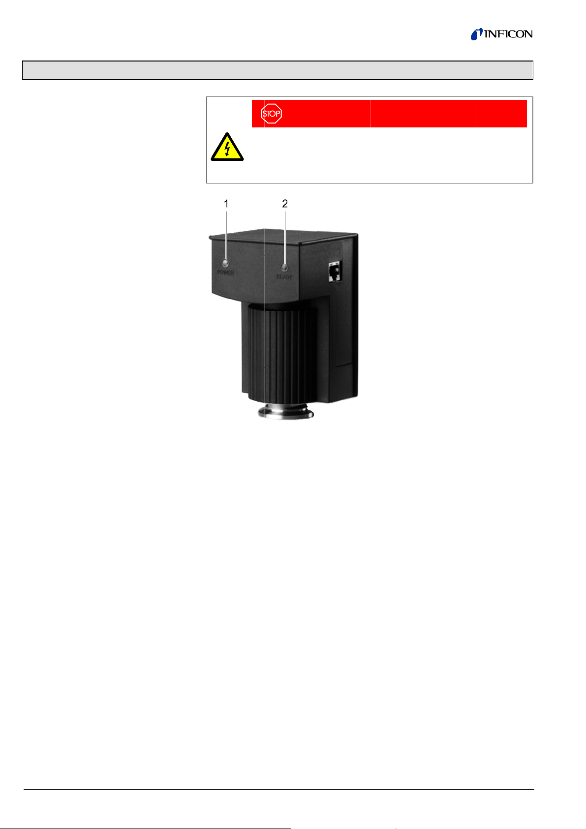
Key to
F
1 LE
D
2 LE
D
1
00. The oran
n
sion switchin
g
> 3×10
-9
mb
a
ments.
e
d on.
n
.
tina14
e
u
ched is appli
e
w
itch off the s
u
the gauge (e
v
n
ge) so as to
h
the high ten
s
F
ig. 6:
D
"POWER" (
o
D
"READY" (g
r
n
ge "POWER"
g
input. See
S
a
r the additio
n
e
1-a (2017-12) PEG100.
o
e
d to the
pply voltage
v
en when
avoid injury
s
ion.
o
range)
r
een)
LED (6/1)
S
ection 3.2.2.
n
al green or
o
m
tina14e1-a (2017-12) PEG100.om 13
In the case of the Penning method of measurement one only may draw conclu-
sions as to proper functioning while the gauge is in the measurement mode, i.e.
when the gas discharge is running.
Trouble-free operation ("READY" LED (6/2) is on, status output HIGH) is marked
by the presence of a pressure dependent signal starting at a pressure of about
3×10⁻⁹ mbar up to the range limit of 1×10⁻² mbar. When the pressure drops
< 3×10⁻⁹ mbar this status is also maintained.
When the “READY” LED (6/2) is not on, status output 0 V:
Cause 1: When the high voltage was switched on the pressure was below
p <3×10⁻⁹ mbar.
Cause 2: No ignition of the gas discharge, even if the power supply voltage is
present, the high tension has been switched on and a pressure between
about 3×10⁻⁹ mbar and 1×10⁻² mbar.
WARNING
Before baking out the sensing cell you must detach the electronics
assembly from the sensing cell. The electronics assembly may be
damaged when exceeding a temperature of 70 °C.
Before baking out, you must make sure that an ultra sealing disc
(PEG100, DN 25 KF) or a copper seal (PEG100, DN 40 CF) is used
as the flange seal.
The PEG100 is equipped with all-metal sensing cells so that any outgassing
caused by polymer seals is entirely avoided.
After having detached the electronics (refer to Section 5.2.1) from the sensing cell,
the outgassing rate of the sensing cell may be reduced considerably by baking out,
so that the accuracy of the measurements in the range below 1×10⁻⁶ mbar is im-
proved.
When using the gauge chiefly in the UHV range (< 10-8 mbar) it is recommended to
remove the cathode plate. This helps to reduce the surface area of the surfaces
which may release gas.
How to proceed in order to detach the electronics assembly is described in Section
5.2 (cleaning of the sensor).
Permissible bake out temperature:
Sensing cell of the PEG100 (DN 25 KF) 150 °C (with ultra sealing disc)
Sensing cell of the PEG100 (DN 40 CF) 350 °C
4.2 Measurement System
Status Indication
4.3 Degassing
14 tina14e1-a (2017-12) PEG100.om
5 Maintenance
DANGER
DANGER: contaminated parts
Contaminated parts can be detrimental to health and environment.
Before you begin to work, find out whether any parts are contami-
nated. Adhere to the relevant regulations and take the necessary
precautions when handling contaminated parts.
Caution
Caution: vacuum component
Dirt and damages impair the function of the vacuum component.
When handling vacuum components, take appropriate measures to
ensure cleanliness and prevent damages.
Caution
Caution: dirt sensitive area
Touching the product or parts thereof with bare hands increases the
desorption rate.
Always wear clean, lint-free gloves and use clean tools when working
in this area.
The electronics assembly of the PEG100 does not require any maintenance.
DANGER
A high tension which is dangerous when touched is applied to the
sensor in the PEG100. You must always switch off the supply voltage
for the PEG100 before starting any work on the gauge (even when
removing the PEG100 from the connection flange) so as to avoid
injury when inadvertently coming in to contact with the high tension.
In order to detach the electronics assembly and the magnet assembly (7/1) you
must loosen the two cross head screws which can be accessed through two holes
in the rear of the PEG100 by turning these by about 1.5 turns.
Then the electronics assembly and the magnet assembly (7/1) may be pulled off
from the sensor housing.
The magnet assembly (7/1) may drop down during the pulling off pro-
cess.
5.1 The Electronics
Assembly
5.2 Cleaning the Sensor
5.2.1 Detaching the
Electronics Assembly

tina14e1-a (2017-12) PE
G
5.2.2 Dis
a
Sen
s
5.2.3 Cle
a
Par
t
5.2.4 Ass
e
G
100.om
a
ssembly
o
s
o
r
a
ning the I
n
t
s
e
mbly of t
h
o
f the
n
dividual
h
e Senso
r
The se
n
(7/2) an
How to
d
1) Use
2) Use
the
p
3) Det
a
Fig. 7
S
In the c
a
steel w
o
blow cl
e
be rem
o
If possi
b
same s
h
cerami
c
taminat
i
The se
n
describ
e
When i
n
remain
s
Moreov
e
When i
n
(7/2) m
u
n
sor consists
o
d the cathod
e
disassemble:
a pair of twe
e
a pair of plie
r
p
liers to and f
r
a
ch the cera
m
S
ensor
Do not da
m
a
se of severe
o
ol or similar
a
e
an with oil-fr
e
o
ved by blowi
n
b
le, the catho
d
h
ould be don
e
c
s protection
d
i
on.
n
sor is reasse
m
e
d in Section
5
n
serting the a
n
s
between the
e
r, make sur
e
n
serting the c
a
u
st not be be
n
o
f the vacuu
m
e
plate (7/5).
S
e
zers to pull t
h
r
s to pull the a
r
o a little.
m
ics disc (7/3)
m
age the seal
contaminatio
n
a
nd then subj
e
e
e pressurize
d
n
g these out
o
d
e plate (7/5)
e
for the anod
e
d
isc (7/3) whic
m
bled in the
r
5
.2.2.
n
ode ring (7/4
wings of the i
e
that the ano
d
a
thode plate (
7
n
t. Therefore i
n
housing, the
S
ee Fig. 7.
h
e cathode pl
a
node ring out
f
rom the curr
e
ing surfaces
o
n
, the inside
o
e
cted to furth
e
d
air or nitrog
e
o
f the housing
.
s
hould be rep
e
ring (7/4) wi
t
h protects the
e
verse order
a
) you must m
a
gnition aid (7
/
d
e ring is lying
7
/5) into the h
n
sert slowly a
n
anode ring (
7
a
te (7/5) out o
from the hou
s
e
nt feed- thro
u
Key to fi
g
1 Mag
n
2 Igniti
o
3 cera
m
4 Ano
d
5 Cath
o
6 Sens
flang
e
o
f the vacuum
o
f the housing
e
r cleaning wi
t
e
n. Any possi
b
.
p
laced by a n
e
t
h the ignition
e
current feed
-
a
s for disass
e
a
ke sure that
a
/
2) and the w
a
g
snug on the
c
ousing the wi
n
nd carefully.
7
/4) with igniti
o
f
the sensor.
s
ing; for this
m
u
gh.
g
. 7:
n
et assembly
o
n aid
m
ics disc
e ring
o
de plate
or housing wi
t
e
flange.
may be clea
n
h alcohol. Fin
b
ly present fla
k
e
w cathode pl
a
aid (7/2) and
-
through agai
n
e
mbly which i
s
a
clearance o
f
a
ll of the hous
i
c
eramics disc
n
gs of the ign
i
15
o
n aid
m
ove
t
h
n
ed with
ally
k
es will
a
te. The
the
n
st con-
s
f
1 mm
i
ng.
.
i
tion aid
16 tina14e1-a (2017-12) PEG100.om
How to proceed:
1) Place the magnet assembly on the sensor.
2) Push the electronics assembly over the magnet assembly and the sensor, and
turn slightly as required until the correct orientation between electronics
assembly and sensor has been found. When the electronics assembly has
been placed as required, the black magnet housing is fully surrounded by the
housing of the PEG100.
3) Retighten the cross head screws at the rear of the gauge.
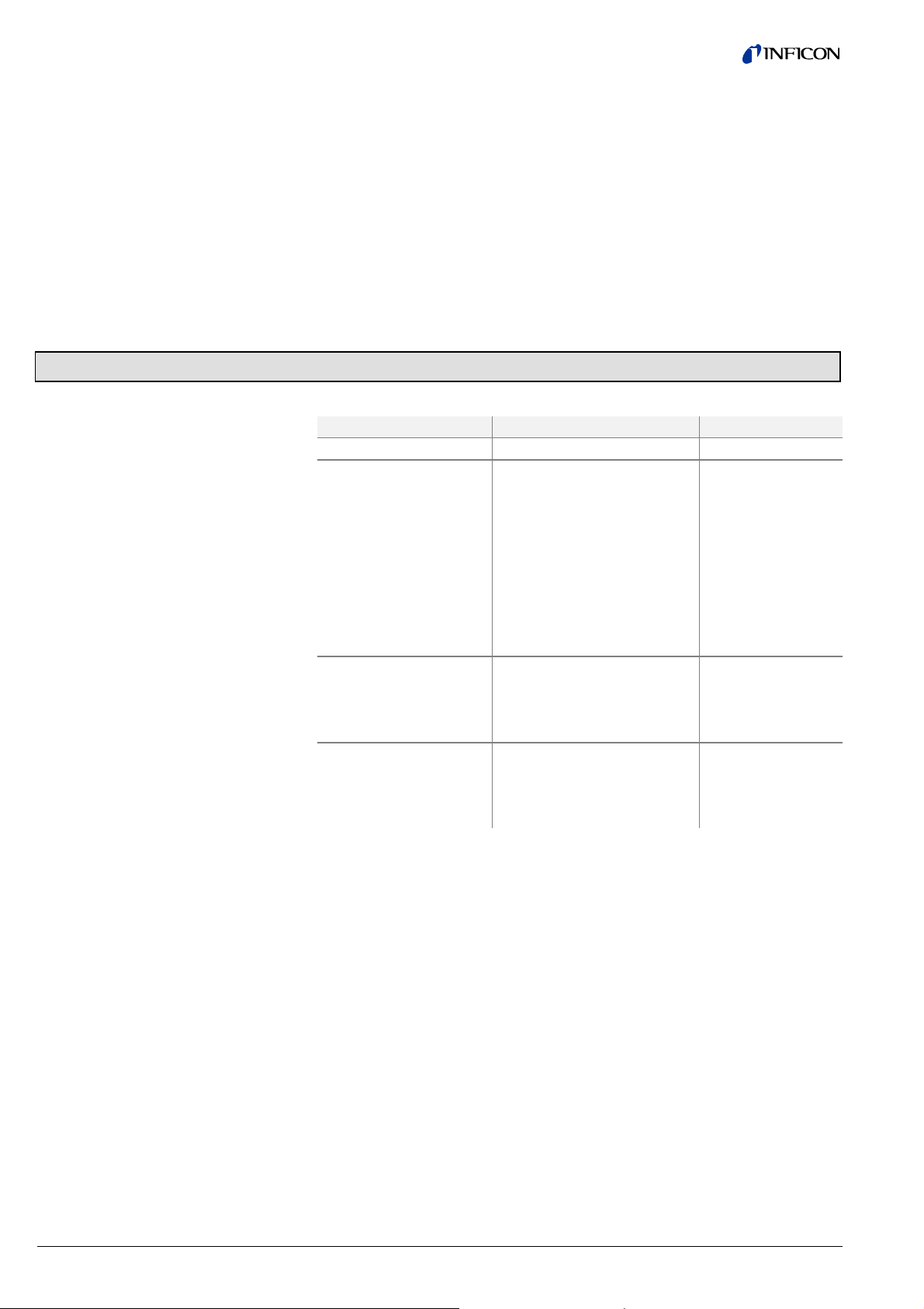
6 Troubleshooting
Problem Possible cause Correction
No LED is on. Supply voltage is missing.
The "POWER" LED (6/1)
is on, the "READY" LED
(6/2) is not on.
High tension has not been ac-
tivated. Pressure has dropped
below < 3×10⁻⁹mbar.
The gas discharge has not
ignited.
Sensing cell not properly con-
nected to the electronics as-
sembly (e.g. after mainte-
nance).
Missing anode ring (e.g. after
maintenance).
The measurement signal
is always greater than
10 V even if the pressure
is much lower than
10-2 mbar.
Short circuit in the sensing
cell.
Clean the sensing
cell. For this refer to
section 5.2.
During pumpdown the
measurement signal re-
mains at some level al-
though the pressure is
dropping.
Contamination within the sen-
sing cell.
Replace the sen-
sing cell.
5.2.5 Assembly of the
Electronics Assembly
tina14e1-a (2017-12) PEG100.om 17
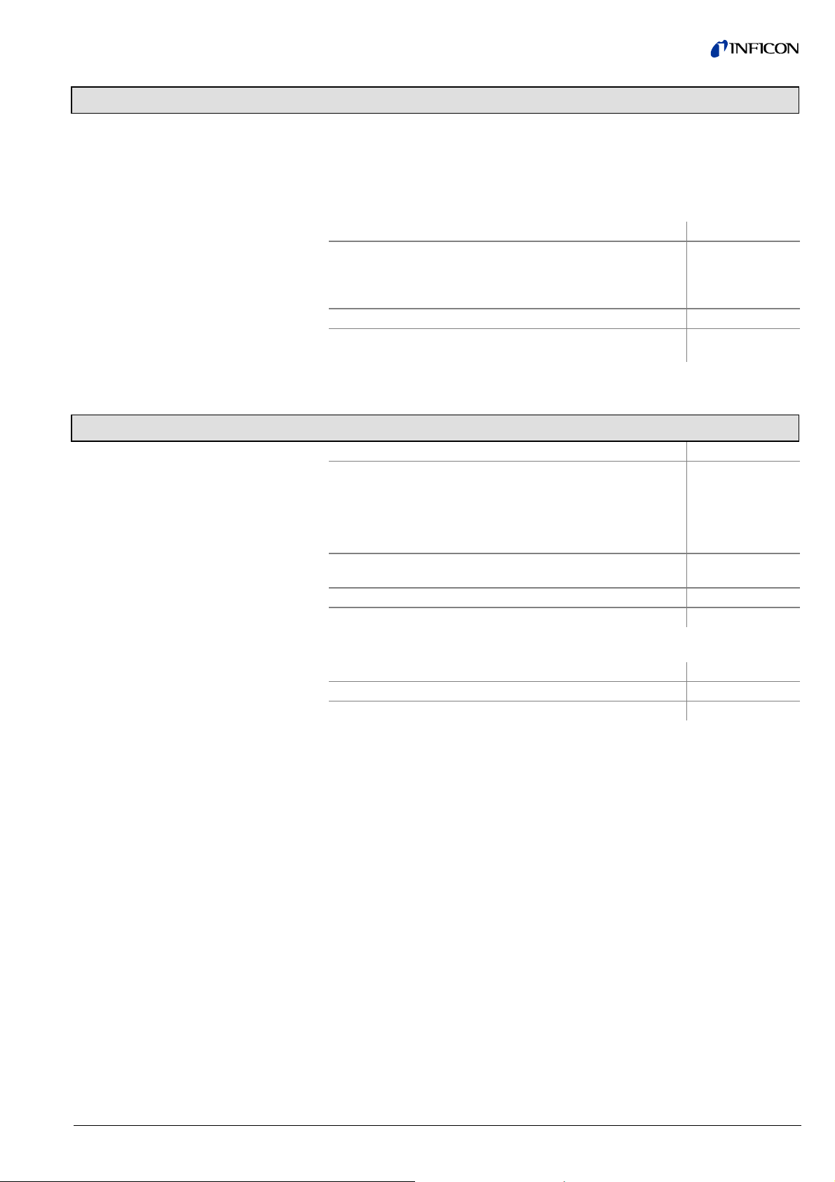
7 Wearing Parts and Original Spare Parts
When ordering spare parts, always indicate:
•all information on the product nameplate
•description and ordering number according to the spare parts list
Ordering number
Replacement kit, consisting of:
Cathode plate of titanium (5 pcs.)
Ceramics disc (5 pcs)
Gauge
351-490
Anode complete with ignition plate 351-499
Sensor (DN 25 KF),
complete with magnet assembly (PEG050)
399-510
Accessories
Ordering number
Connection cable with two FCC 68 plugs, screened 3 m
5 m
10 m
15 m
20 m
30 m
398-500
398-501
398-502
398-503
398-504
398-505
Pirani Standard Gauge PSG500-S (DN 16 ISO-KF)
PSG500-S (DN 16 CF-R)
350-080
350-082
DN 20 / 25 KF clamping ring 211-002
DN 25 KF (Al) centering ring 211-061
Ordering number
Ultra sealing disc (3 pcs.) 211-168
Clamping ring for ultra sealing discs 211-009
For overpressure operation and
degassing:
18 tina14e1-a (2017-12) PEG100.om
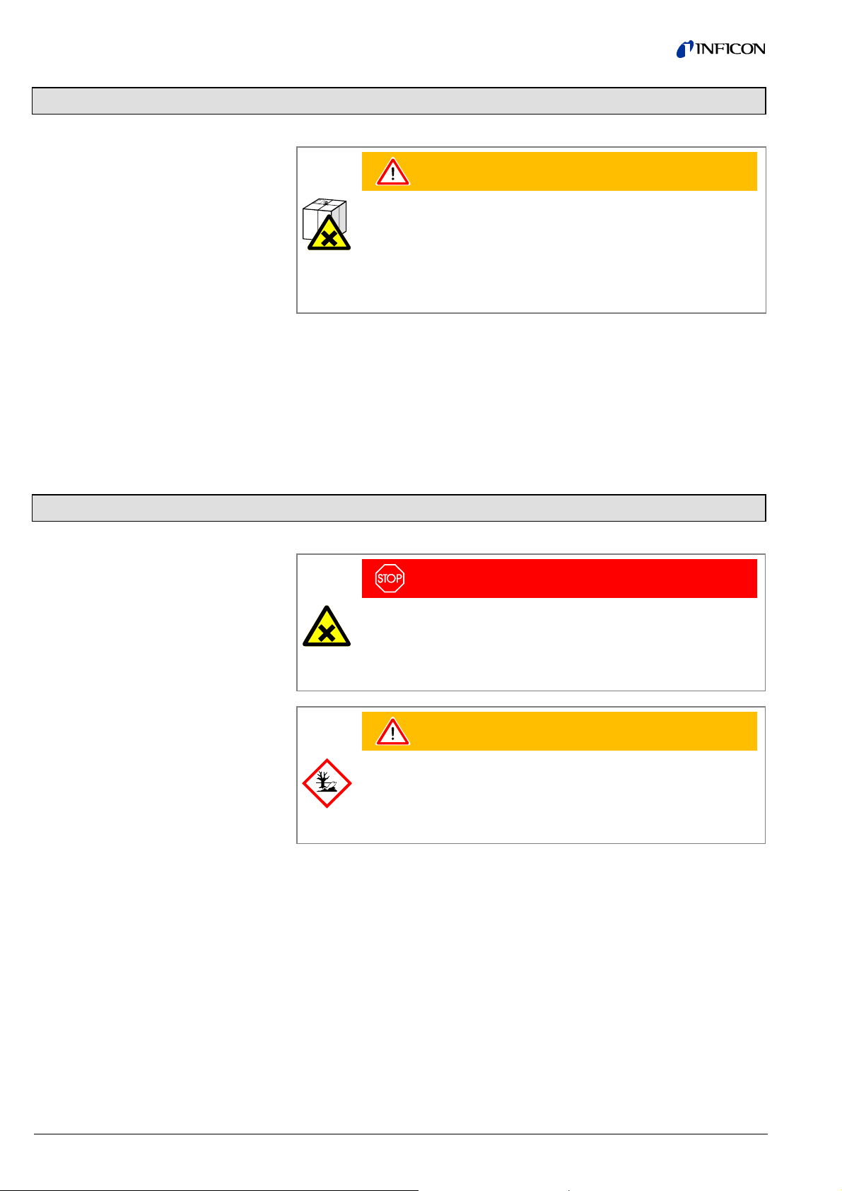
9 Returning the Product
WARNING
WARNING: forwarding contaminated products
Products returned to INFICON for service or repair should, if possible,
be free of harmful substances (e.g. radioactive, toxic, caustic or micro-
biological). Otherwise, the type of contamination must be declared.
Adhere to the forwarding regulations of all involved countries and for-
warding companies and enclose a completed contamination declara-
tion (Form under www.inficon.com).
Products that are not clearly declared as "free of harmful substances" are de-
contaminated at the expense of the customer.
Products not accompanied by a duly completed declaration of contamination are
returned to the sender at his own expense.
10 Disposal
DANGER
DANGER: contaminated parts
Contaminated parts can be detrimental to health and environment.
Before beginning to work, find out whether any parts are contami-
nated. Adhere to the relevant regulations and take the necessary pre-
cautions when handling contaminated parts.
WARNING
WARNING: substances detrimental to the environment
Products or parts thereof (mechanical and electric components,
operating fluids etc.) can be detrimental to the environment.
Dispose of such substances in accordance with the relevant local
regulations.
After disassembling the product, separate its components according to the
following criteria:
Contaminated components (radioactive, toxic, caustic or biological hazard etc.)
must be decontaminated in accordance with the relevant national regulations,
separated according to their materials, and disposed of.
Such components must be separated according to their materials and recycled.
Separating the components
Contaminated components
Other components

tina14e1-a (2017-12) PEG100.om 19
Appendix
(U = 0.4 V; "not ignited")
U (Out)
[V]
Pressure
[mbar]
U Out)
[V]
Pressure
[mbar]
U (Out)
[V]
Pressure
[mbar]
U (Out)
[V]
Pressure
[mbar]
0,667 1,00E-09 3,4 1,12E-07 6 1,00E-05 8,6 8,91E-04
0,8 1,26E-09 3,5 1,33E-07 6,1 1,19E-05 8,7 1,06E-03
1 1,78E-09 3,6 1,59E-07 6,2 1,41E-05 8,8 1,26E-03
1,1 2,11E-09 3,7 1,88E-07 6,3 1,68E-05 8,9 1,50E-03
1,2 2,51E-09 3,8 2,24E-07 6,4 2,00E-05 9 1,78E-03
1,3 2,99E-09 3,9 2,66E-07 6,5 2,37E-05 9,1 2,11E-03
1,4 3,55E-09 4 3,16E-07 6,6 2,82E-05 9,2 2,51E-03
1,5 4,22E-09 4,1 3,76E-07 6,7 3,35E-05 9,3 2,99E-03
1,6 5,01E-09 4,2 4,47E-07 6,8 3,98E-05 9,4 3,55E-03
1,7 5,96E-09 4,3 5,31E-07 6,9 4,73E-05 9,5 4,22E-03
1,8 7,08E-09 4,4 6,31E-07 7 5,62E-05 9,6 5,01E-03
1,9 8,41E-09 4,5 7,50E-07 7,1 6,68E-05 9,7 5,96E-03
2 1,00E-08 4,6 8,91E-07 7,2 7,94E-05 9,8 7,08E-03
2,1 1,19E-08 4,7 1,06E-06 7,3 9,44E-05 9,9 8,41E-03
2,2 1,41E-08 4,8 1,26E-06 7,4 1,12E-04 10 1,00E-02
2,3 1,68E-08 4,9 1,50E-06 7,5 1,33E-04
2,4 2,00E-08 5 1,78E-06 7,6 1,59E-04
2,5 2,37E-08 5,1 2,11E-06 7,7 1,88E-04
2,6 2,82E-08 5,2 2,51E-06 7,8 2,24E-04
2,7 3,35E-08 5,3 2,99E-06 7,9 2,66E-04
2,8 3,98E-08 5,4 3,55E-06 8 3,16E-04
2,9 4,73E-08 5,5 4,22E-06 8,1 3,76E-04
3 5,62E-08 5,6 5,01E-06 8,2 4,47E-04
3,1 6,68E-08 5,7 5,96E-06 8,3 5,31E-04
3,2 7,94E-08 5,8 7,08E-06 8,4 6,31E-04
3,3 9,44E-08 5,9 8,41E-06 8,5 7,50E-04
A: Output Voltage vs.
Pressure

20 tina14e1-a (2017-12) PEG100.om
Example for connecting the PEG100: Switching the high tension via an external switch or contact
Example for connecting the PEG100: Switching the high tension automatically through a Pirani Standard
Gauge with switching point
B: Examples for
Connecting
Table of contents


