BigDog diablo mp bac-vac User manual

121913 REV B
BIGDOG®MOWER CO. DIABLO®MP BAC-VAC™
Operator’s Manual
200 South Ridge Road
Hesston, Kansas
67062

REV B 121913

121913 toc-1 REV B
Table of Contents
General Information . . . . . . . . . . . . . . . . . . . . . . . . . . . . . . . . . . . . . . . . . . . . . 1-1
To The New Owner . . . . . . . . . . . . . . . . . . . . . . . . . . . . . . . . . . . . . . . . . . . 1-1
Using This Manual . . . . . . . . . . . . . . . . . . . . . . . . . . . . . . . . . . . . . . . . . . . 1-1
Warranty Registration . . . . . . . . . . . . . . . . . . . . . . . . . . . . . . . . . . . . . . . . 1-1
Parts and Service . . . . . . . . . . . . . . . . . . . . . . . . . . . . . . . . . . . . . . . . . . . . 1-1
Safety Precautions . . . . . . . . . . . . . . . . . . . . . . . . . . . . . . . . . . . . . . . . . . . . . . 2-1
Safe Operation and Service Precautions. . . . . . . . . . . . . . . . . . . . . . . . . 2-1
Safety and Instruction Decals . . . . . . . . . . . . . . . . . . . . . . . . . . . . . . . . . 2-2
Assembly Instructions . . . . . . . . . . . . . . . . . . . . . . . . . . . . . . . . . . . . . . . . . . . 3-1
Packing List . . . . . . . . . . . . . . . . . . . . . . . . . . . . . . . . . . . . . . . . . . . . . . . . 3-1
Deck Adapter Kits. . . . . . . . . . . . . . . . . . . . . . . . . . . . . . . . . . . . . . . . . . . . 3-1
Mower Deck Preparation. . . . . . . . . . . . . . . . . . . . . . . . . . . . . . . . . . . . . . 3-2
122170 (60") Adapter Assembly. . . . . . . . . . . . . . . . . . . . . . . . . . . . . . . . 3-3
122171 (72") Adapter Assembly. . . . . . . . . . . . . . . . . . . . . . . . . . . . . . . . 3-4
Mower Preparation . . . . . . . . . . . . . . . . . . . . . . . . . . . . . . . . . . . . . . . . . . 3-5
BAC-VAC™ Mount Assembly . . . . . . . . . . . . . . . . . . . . . . . . . . . . . . . . . . . 3-5
Frame Cover Assembly Installation . . . . . . . . . . . . . . . . . . . . . . . . . . . . . 3-6
Final Connection . . . . . . . . . . . . . . . . . . . . . . . . . . . . . . . . . . . . . . . . . . . 3-10
BAC-VAC™ Assembly . . . . . . . . . . . . . . . . . . . . . . . . . . . . . . . . . . . . . . . . 3-10
Weight Assembly . . . . . . . . . . . . . . . . . . . . . . . . . . . . . . . . . . . . . . . . . . . 3-12
Operation . . . . . . . . . . . . . . . . . . . . . . . . . . . . . . . . . . . . . . . . . . . . . . . . . . . . . . 4-1
Collecting and Vacuum Pickup. . . . . . . . . . . . . . . . . . . . . . . . . . . . . . . . . 4-1
Unloading the BAC-VAC™ . . . . . . . . . . . . . . . . . . . . . . . . . . . . . . . . . . . . . 4-1
Converting To Side Discharge Mode . . . . . . . . . . . . . . . . . . . . . . . . . . . . 4-1
Removing the BAC-VAC™ . . . . . . . . . . . . . . . . . . . . . . . . . . . . . . . . . . . . . 4-2
Maintenance & Storage . . . . . . . . . . . . . . . . . . . . . . . . . . . . . . . . . . . . . . . . . . 5-1
Blower Housing and Flex Tube Maintenance . . . . . . . . . . . . . . . . . . . 5-1
Blower Drive Belt . . . . . . . . . . . . . . . . . . . . . . . . . . . . . . . . . . . . . . . . . . . . 5-1
BAC-VAC™ Hopper . . . . . . . . . . . . . . . . . . . . . . . . . . . . . . . . . . . . . . . . . . . 5-1
BAC-VAC™ Hopper Switch Adjustment . . . . . . . . . . . . . . . . . . . . . . . . . . 5-2
Blower Impeller. . . . . . . . . . . . . . . . . . . . . . . . . . . . . . . . . . . . . . . . . . . . . . 5-3
Storage . . . . . . . . . . . . . . . . . . . . . . . . . . . . . . . . . . . . . . . . . . . . . . . . . . . . 5-3
BAC-VAC™ Warranty Policy . . . . . . . . . . . . . . . . . . . . . . . . . . . . . . . . . . . . . . . 6-1
Parts List . . . . . . . . . . . . . . . . . . . . . . . . . . . . . . . . . . . . . . . . . . . . . . . . . . . . . . 7-1

REV B toc-2 121913

121913 1-1 REV B
GENERAL INFORMATION
To The New Owner
The purpose of this manual is to assist owners and opera-
tors in maintaining and operating the Big Dog®Mowers Dia-
blo MP BAC-VAC™. Please read it carefully; information and
instructions furnished can help you achieve years of depend-
able performance.
Using This Manual
This manual contains general operation information as
well as basic adjustment and maintenance information.
Since operating conditions vary considerably, all conditions
cannot be addressed individually. Through training and expe-
rience, operators should develop safe operating practices
suitable to most conditions.
Directions used in this manual, for example RIGHT or LEFT,
refer to directions when in the operator position and facing
forward, unless otherwise stated.
Though current at the time of printing, photographs and
illustrations shown may vary slightly from your mower due to
subsequent production changes. Big Dog®Mower Company
reserves the right to redesign and change the machine as
deemed necessary, without notification. If a change has been
made to your machine which is not reflected in this manual,
contact your Big Dog®Mower Dealer for current information.
Warranty Registration
Your Big Dog®Mowers Dealer must register this attach-
ment on-line within ten (10) days following date of purchase
to validate your warranty protection. As the new equipment
owner, you should confirm that your Big Dog®Mowers Dealer
has registered your attachment with Big Dog®Mowers.
Be sure to register the mower plus each attachment that
displays a model and serial identification number plate with
Big Dog®Mowers.
IMPORTANT: Any unauthorized modification, alteration,
or use of non-approved attachments voids the warranty and
releases Big Dog®Mowers from any liability arising from sub-
sequent use of this equipment. Do not use or operate any
attachment which is not approved by Big Dog®Mowers.
Parts and Service
Use only original Big Dog®Mower replacement parts avail-
able from your local Big Dog®Mower Dealer. For prompt, effi-
cient service, always provide the following information when
ordering parts:
1. Correct part description.
2. Correct part number.
3. Correct model number.
4. Correct serial number.
All arrangements for warranty repair and service must be
handled through an authorized Big Dog®Mower Dealer.

REV B 1-2 121913

121913 2-1 REV B
SAFETY PRECAUTIONS
This safety alert symbol is used to call attention to a mes-
sage intended to provide a reasonable degree of PERSONAL
SAFETY for operators and other persons during the normal
operation and servicing of this equipment.
This manual uses two other words to highlight information.
IMPORTANT calls attention to special mechanical informa-
tion and NOTE emphasizes general information worthy of
special attention.
All operators and mechanics should read this manual, and
be instructed about safe operating and maintenance proce-
dures. If the operators or mechanics cannot read and under-
stand English, it is the owner’s responsibility to explain this
material to them.
Improper use or maintenance by the operator or owner can
result in injury. To reduce the potential for injury, comply with
these safety instructions and always pay attention to the
safety alert symbol “”, which means DANGER or WARNING
- “personal safety instructions.” Failure to comply with the
instructions may result in personal injury or death.
Incorrect usage of this attachment may result in severe
injury. Personnel operating and maintaining it should be trained
in the proper use and should read the manuals completely and
thoroughly before attempting to set-up, operate, adjust, or ser-
vice this mower.
Safe Operation and Service Precautions
Evaluate the terrain to determine what accessories
and attachments are needed to properly and safely
perform the job. Only use accessories and attach-
ments approved by the manufacturer.
Never leave a running mower unattended. Before leav-
ing the operator’s seat for any reason, including emp-
tying the catcher or unclogging the chute:
•Always stop on level ground.
•Disengage the deck clutch.
•Place the steering control levers in the park brake
position.
•Stop the engine.
•Remove the ignition key.
•Wait for the engine and all moving parts to come
to a complete stop.
Always be aware of any obstructions, especially small
children, when backing or unloading the hopper.
Always keep safety shields and covers in place, except
for servicing.
Never work on the blower assembly or the mower deck
when the mower’s engine is running.
Never operate machine with the hopper in the open
position except for unloading.
Never attempt high speed maneuvering in crowded or
congested areas.
Always operate with the complete BAC-VAC™ system,
mulching system or side discharge chute in place and
in the lowest position.
Always keep clear of the mower blades and attach-
ments during their operation.
Turn off the blades when not mowing.
Stop the engine before removing the BAC-VAC™ or
unclogging the discharge chute. Never clear the dis-
charge chute with the engine running. Turn off the
engine and be sure the blades have stopped before
cleaning. Use a probe to clear a plugged discharge
area. Never use your hand!
Clean flammable material from the machine. Prevent
fires by keeping the engine compartment, exhaust area,
battery, fuel line, fuel tank and operator’s station clean of
accumulated trash, grass clippings, and other debris.
Always clean up spilled fuel and oil.
Grass collection system components are subject to
wear, damage and deterioration, which could expose
moving parts or allow objects to be thrown. Frequently
check components and replace with manufacturer’s
recommended parts when necessary.
Never direct discharged material toward anyone. Avoid
discharging material against a wall or obstruction.
Material may ricochet back toward the operator.
Always disengage the blades and wait for them to stop
before crossing gravel drives, walks or roads.
– denotes immediate hazards which WILL result in
severe personal injury or death.
– denotes a hazard or unsafe practice which COULD
result in severe personal injury or death.
DANGER
WARNING

REV B 2-2 121913
Safety and Instruction Decals
The decals are designed to give the operator brief informa-
tion needed in the daily operation and service of the mower.
These decals are not intended to be used in place of this
manual but instead are to be used as an extension of this
manual. These decals should not be removed or obliterated.
Replace these decals if they become unreadable.
•It is the owner’s responsibility to make certain that the
operators and mechanics read and understand this
manual and all decals before operating this mower.
•It is also the owner’s responsibility to make certain that
the operators and mechanics are qualified and physi-
cally able individuals, properly trained in the operation
of this equipment.
•All operators and mechanics must become familiar
with the safe operation of the equipment, operator
controls and decals.
•Never let children or untrained people operate or ser-
vice the equipment. Local regulations may restrict the
age of the operator.
•The owner/user can prevent and is responsible for
accidents or injuries occurring to themselves, other
people or property.
•The owner should also ensure that the operators/
mechanics know that they are responsible for their
own safety as well as the safety of other persons
within the vicinity. Remember, the operator is responsi-
ble for accidents or hazards occurring to other people
or their property.
The following illustrations show the various safety decals
that are located on the mower. A brief explanation, for those
requiring one, is shown to help the operator understand the
meanings of these decals.
Specific safety warning decals are located on the
equipment near the immediate areas of potential
hazards. These decals should not be removed or
obliterated. Replace them if they become non-read-
able.
WARNING:
Thrown objects!
Part Number 601624
•Never operate the mower deck with side
deflector damaged, altered, removed or in
raised position, except when the entire
grass catcher attachment or mulching sys-
tem is being used.
WARNING
DANGER:
Rotating blades, pulleys & belts
•Keep shields and covers in place
while machine is in operation
•Keep hands, feet and clothing
away from rotating pulleys and
belts.
Part Number 601837
Part Number 602758
•Read the Operator’s Manual before
attempting to operate this machine.
•Wear ear protection, eye protection
and safety shoes when operating
this equipment.
Part Number 602757
DANGER: Rotating impeller
•Keep hands, feet and clothing away.
•Keep shields or covers in place while the
machine is in operation.
•Stop the engine, remove the ignition key.
•Engage the park brake.
•Use a probe to clear debris from the
blower assembly. Remove blower chute
to clear debris from chute.
•Never engage the mower deck unless the
entire grass catcher attachment is prop-
erly installed.
Part Number 603940
WARNING: Crushing body
•Stay clear of the raised hopper door.
•Never get between the hopper door and the
hopper container.
•Do not reach or climb into the hopper.
•Never reach into the hopper door opening or
the hopper door linkage area.
Part Number 603967
WARNING: Crushing hand or foot
•Never reach into the crushing danger zone.
•Keep hands and feet away.
601837
602758
602757
603940
603967

121913 3-1 REV B
ASSEMBLY INSTRUCTIONS
These instructions apply to the assembly of the Big Dog®
Mowers 934463 BAC-VAC™ to a Big Dog® Diablo MP 60” or
72” mower with serial numbers 140400001 and higher.
It is intended that these units be installed by trained Big
Dog®Mowers service personnel. If additional assistance is
required, contact the Big Dog®Mowers Customer Service
Department.
Directions given in these instructions, for example LEFT
and Right, refer to direction while seated on the mower.
Before proceeding, read through the following instructions
to familiarize yourself with them, while at the same time iden-
tify and inventory kit parts supplied.
Unpack and inspect all parts. Notify the carrier of any ship-
ping damages immediately.
Packing List
Deck Adapter Kits
The following adapter kits must be used when mounting
the BAC-VAC™ to a particular deck.
Part No. Description Qty
120332 BLOWER ASSEMBLY 1
N/A WEIGHT ASSEMBLY 1
603935 WIRING HARNESS 1
N/A BAC-VAC™ ASSEMBLY 1
N/A CONTROL PANEL 1
768523 FW .343 X .687 X .051/.080H 11
036236 CS .312-18 X 1.00 HX G5 7
000331 WIRE TIE 7
086660 NT .375-16 HXZY NL 6
767954 FW .406 X .812 X .060 SAE 6
017616 CS .500-13 X 1.75 HX G5 6
767962 FW .531 X 1.063 X .090 SAE 20
008193 NT .500-13 HX G5 ZNYC 8
078386 FW .510 X 1.750 X .18 ZNYC 2
705954 CS .500-13 X 1.25 HX G5 ZN 6
604423 UB .375-16 X 2.00 X 4.50 SQ 2
053702 CE .620 X 3.0 X .15 X 2.84 2
704783 FW .625 X 1.50 X .105 ZN 4
023036 HP .148 X 2.690 ZN 2
603356 FLEX TUBE 1
115933 LH MOUNT 1
118150 RH MOUNT 1
116714 MOUNT SPACER 1
604576 MUFFLER EXTENSION 1.5" 1
604577 MUFFLER EXTENSION 1.375" 1
769299 SC #10 X.750 PHILLIPS 1
034280 CS .312-18 X .75 HX G5 4
025395 CB .375-16 X 1.00 HX G5 2
017616 CS .500-13 X 1.750 HX G5 6
119745 INLET W/A 1
Deck Size Adapter Kit P/N
60” 122170
72” 122171
REV B 3-2 121913
Mower Deck Preparation
1. Before proceeding:
•Park the mower on level ground.
•Disengage the deck clutch.
•Place the steering control levers in the park brake
position.
•Stop the engine.
•Remove the ignition key.
•Wait for the engine and all moving parts to come
to a complete stop.
•Disconnect the negative battery cable.
2. Remove the discharge chute and torsion spring.
NOTE: Retain these parts as they will be re-installed
when the BAC-VAC™ is removed.
3. Release the deck drive belt tension.
4. Remove the existing spindle bolt and pulley from the
center blade spindle.
Replace the pulley with the double pulley and place the
new cup washer between the head of the new bolt and
the drive pulley. Thread the cup washer and bolt
assembly into the spindle shaft. Torque the bolt to 118
ft.-lbs. Refer to Figure 3-2 or Figure 3-3.
5. Attach the blower baffle to the deck. Refer to
Figure 3-2 or Figure 3-3.
6. Assemble the blower mount to the blower assembly.
Refer to Figure 3-2 or Figure 3-3.
7. Attach the blower assembly to the deck by inserting
the rod through the discharge chute bracket and the
blower mount and secure with a nut. Refer to
Figure 3-2 or Figure 3-3.
8. Place the deck drive belt around the lower pulley of the
double pulley. Confirm that the belt is properly routed
and seated on all pulleys and idlers. Re-tension the
deck drive belt using the spring anchor bracket. Ten-
sion the belt per the tensioning instructions found in
the mower’s General Service Manual.
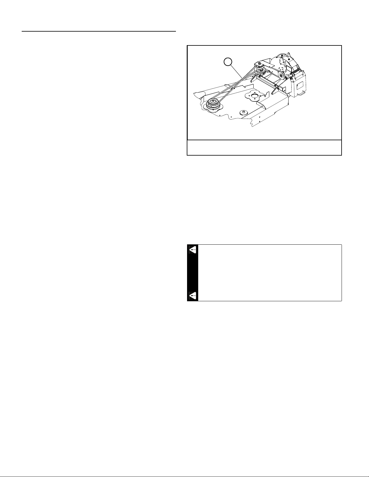
9. Install and route the blower belt around the blower pul-
leys and the upper pulley on the double pulley. This
belt is self-tensioning. Figure 3-1
10. Remove the front right side deck lift chain and attach
the rigid link to the deck lift arm. Refer to Figure 3-2 or
Figure 3-3.
Position the center drive bracket on the deck as shown
and attach it and the rigid link to the deck.
NOTE: The rigid link must move freely in the top slot and
rotate freely in the bottom hole.
11. Attach the center drive cover. Refer to Figure 3-2 or
Figure 3-3.
A. Blower belt
Figure 3-1
Do not operate the deck without the discharge chute
or complete BAC-VAC™ system in place.
A
WARNING

121913 3-3 REV B
Figure 3-2
2
11
3
4
4
4
5
6
7
9
10
11
12
14
13
3
8
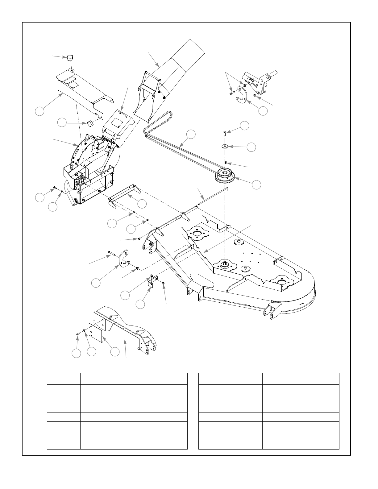
INDEX NO. PART NO. DESCRIPTION INDEX NO. PART NO. DESCRIPTION
1 552081 CENTER DRIVE COVER 8 074252 CS .500-13 X 1.50 HX G5
2 792002 KNOB 5/16-18 X 3/4" 9 752386 CW .515 X 2.25 X .204 BLK
3 036244 CS .375-16 X 1.00 HX G5 10 603311 DOUBLE DRIVE PULLEY
4 767954 FW .406 X .812 X .060 SAE 11 117762 RIGID LINK
5 117758 BLOWER MOUNT 12 601069 CN .312-18 X .20 MAX THK
6 054502 NT .375-16 HX G5 ZNY 13 115773 CENTER DRIVE BRACKET
7 603806 110.5" EL A-SEC BELT 14 117696 BAFFLE
122170 (60") Adapter Assembly
Existing
hardware
Blower
assembly
Existing
hardware
Existing
hardware
Discharge
cover
Outlet tube and
adapter assembly
Existing
hardware
Existing
hardware
Notch
Existing
rod
Torque to 65-
75 ft.-lbs.
Deck discharge
opening
Existing
hardware
1
Existing
hardware
Existing
hardware
REV B 3-4 121913
Figure 3-3
122171 (72") Adapter Assembly
2
11
3
4
4
4
5
6
7
9
10
11
12
14
13
3
Existing
hardware
Blower
assembly
Existing
hardware
Discharge
cover
Outlet tube and
adapter assembly
Existing
hardware
Existing
hardware
Notch
Existing
rod
Deck discharge
opening
8
Existing
hardware
1
Existing
hardware
Existing
hardware
INDEX NO. PART NO. DESCRIPTION INDEX NO. PART NO. DESCRIPTION
1 552082 CENTER DRIVE COVER 8 074252 CS .500-13 X 1.50 HX G5
2 792002 KNOB 5/16-18 X 3/4" 9 752386 CW .515 X 2.25 X .204 BLK
3 036244 CS .375-16 X 1.00 HX G5 10 603712 DOUBLE DRIVE PULLEY
4 767954 FW .406 X .812 X .060 SAE 11 117768 RIGID LINK
5 117758 BLOWER MOUNT 12 601069 CN .312-18 X .20 MAX THK
6 054502 NT .375-16 HX G5 ZNY 13 115773 CENTER DRIVE BRACKET
7 604703 BELT, 119.00" EL 14 117702 BAFFLE
Existing
hardware
Torque to
65-75 ft.-lbs.

121913 3-5 REV B
Mower Preparation
1. Attach the correct muffler extension to the muffler out-
let tube using the self tapping screw shown. Figure 3-4
IMPORTANT: Tailpipe and tailpipe extension become
very hot during operation. These parts must not be
allowed to contact the catcher shell during operation or
while the mower is hot.
2. Remove the two cap screws that attach the left side of
the rear bumper to the mower frame. Figure 3-5
3. Attach the left side mount to the rear bumper and the
mower frame using the hardware shown. Figure 3-5
4. Repeat steps 2 & 3 for the opposite side. Figure 3-5
5. Attach the mount spacer to the left and right mounts
as shown. Figure 3-5
6. Tighten all hardware.
Allow the engine and muffler to cool before assem-
bling the unit to the mower.
WARNING
Figure 3-4
INDEX
NO. PART NO. DESCRIPTION
1 604576 MUFFLER EXTENSION 1.5" (KAWASAKI
FX1000 ENGINE)
604577 MUFFLER EXTENSION 1.375" (KAWASAKI
FX850 ENGINE)
2 769299 SC #10 X.750 PHILLIPS
1
2
Muffler outlet tube
Figure 3-5
INDEX
NO. PART NO. DESCRIPTION
1 118243 MOUNT SPACER
2 116739 MOUNT, LS
3 116740 MOUNT, RS
4 017616 CS .500-13 X 1.750 HX G5
5 767962 FW .531 X 1.063 X .090 SAE
6 008193 NT .500-13 HX G5 ZNYC
7 078386 FW .510 X 1.750 X .18 ZNYC
8 705954 CS .500-13 X 1.250 HX G5 ZN
6
6
3
7
6
5
2
8
41
BAC-VAC™ Mount Assembly
Rear
bumper
8
7
5
5
5
4
5
5
5

REV B 3-6 121913
Frame Cover Assembly Installation
1. Raise the seat and seat platform to allow access to
the area underneath the seat.
2. The BAC-VAC™ frame harness should be routed on the
mower as shown. Figure 3-6
3. Remove the existing left side frame cover and right
side frame cover from the mower. Figure 3-8 &
Figure 3-9
4. Unbolt the hose clamp from the mower frame that the
wiring harness to the control panel goes through. Do
not remove the wiring harness from the clamp.
Figure 3-10
5. Route the BAC-VAC™ frame harness pigtail that has
the two connector bodies through the hose clamp and
retighten clamp hardware. Figure 3-10
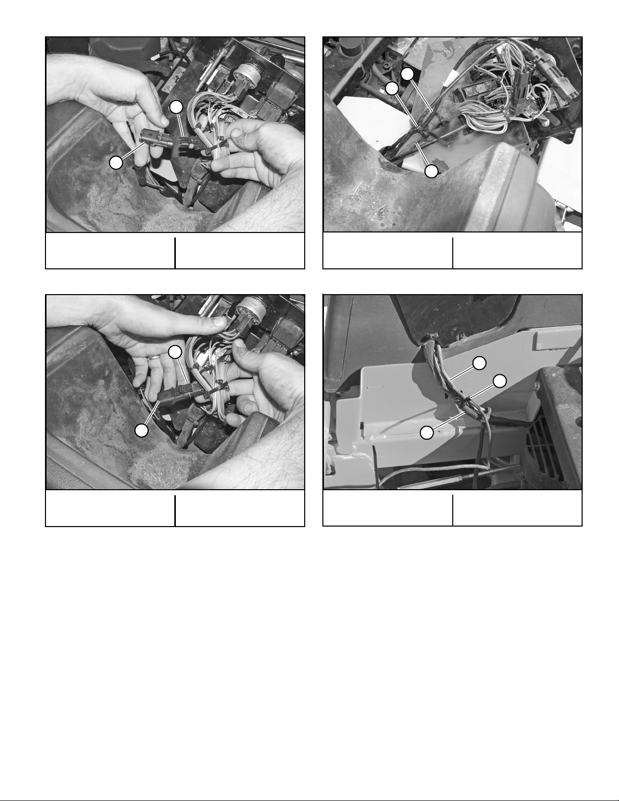
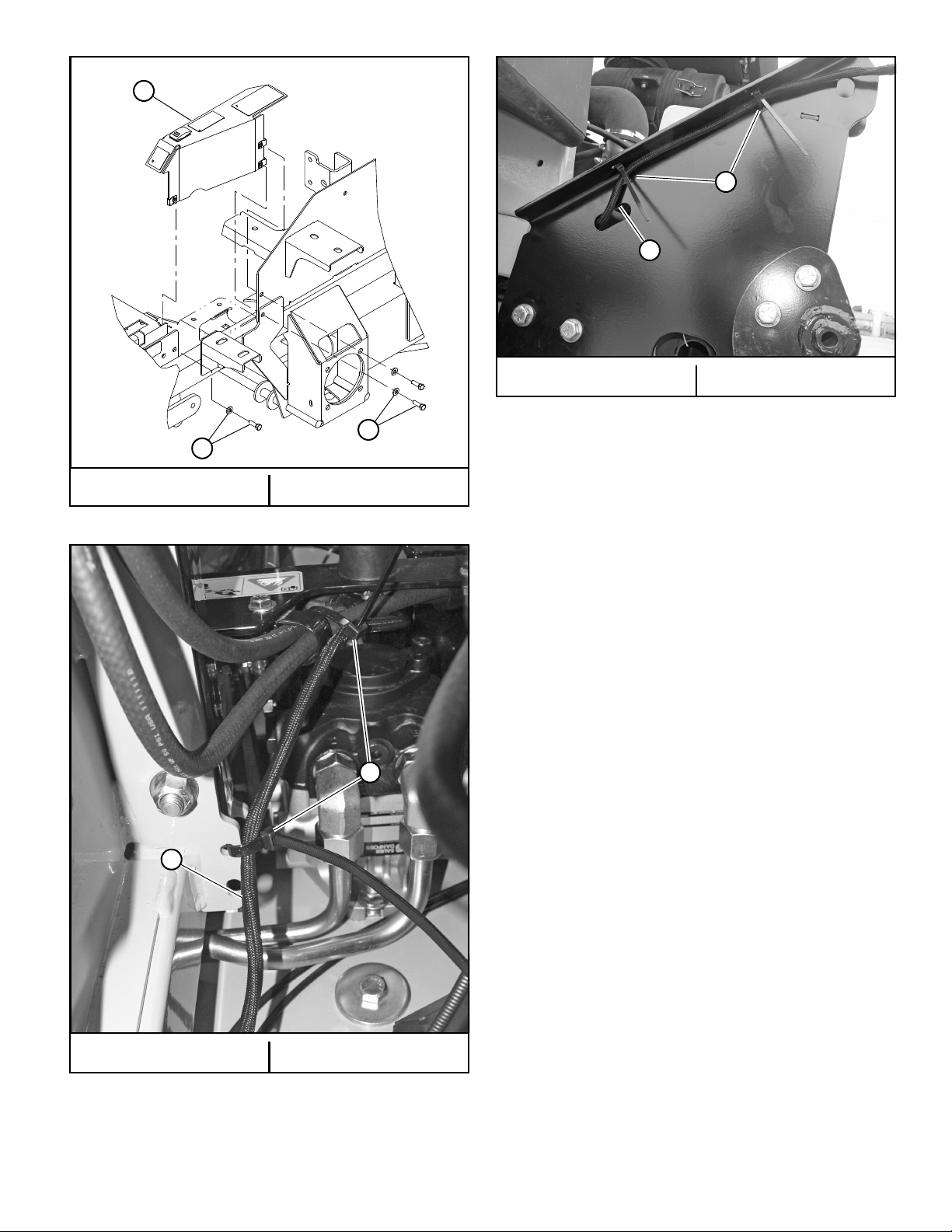
6. Remove the mower’s control panel.
7. Locate the auxiliary connector body underneath the
control panel and remove the cap. Figure 3-11
8. Plug the BAC-VAC™ frame harness connector into
the auxiliary plug. Figure 3-12
9. Secure the BAC-VAC™ frame harness to the main
mower harness with a wire tie. Figure 3-13
10. Re-attach the mower control panel. Make sure that the
wiring harnesses are routed through the slot in the
bottom of the control panel correctly. Secure the BAC-
VAC™ frame harness to the main mower harness.
Figure 3-13
11. Re-attach the right frame cover to the mower frame.
Figure 3-14
A. Frame harness
Figure 3-6
A. Right side frame cover
Figure 3-7
A
A
A
A. Remove this hardware B. Existing left side frame
cover
Figure 3-8
A. Frame harness B. Hose clamp
Figure 3-9
B
A
B
A
121913 3-7 REV B
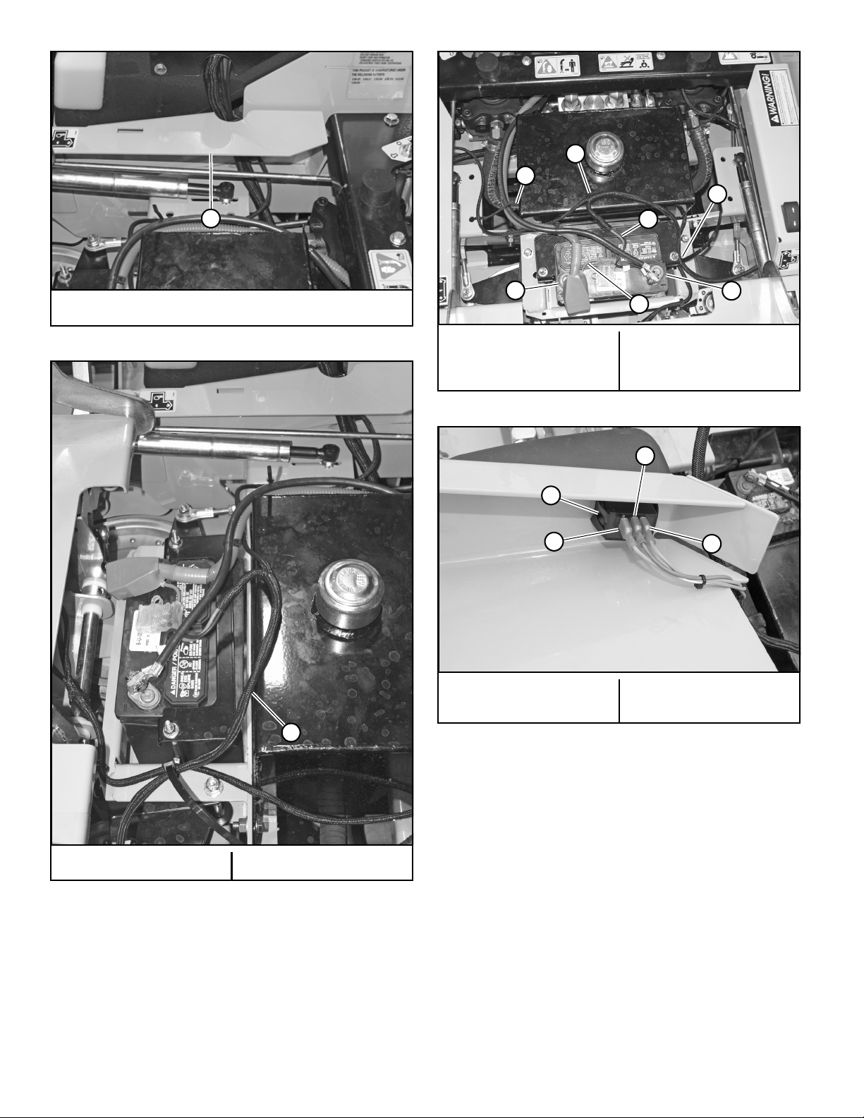
12. Route the BAC-VAC™ frame harness as shown and
connect the appropriate wires to the battery terminals.
Secure the BAC-VAC™ frame harness to the mower
using the wire ties as shown. Make sure that none of
the harness will come in contact with any moving
parts. Figure 3-15 & Figure 3-16
13. Attach the three wires on the wiring harness to the
BAC-VAC™ switch. Figure 3-17
14. Attach the left frame cover assembly to the mower
frame. Figure 3-18
15. Route the BAC-VAC™ frame harness along the left side
of the mower frame as shown. Secure the harness to
the mower using the wire ties as shown. Figure 3-19 &
Figure 3-20
A. Cap B. Auxiliary connector
body
Figure 3-10
A. Cap B. Auxiliary connector
body
Figure 3-11
A
B
A
B
A. Frame harness
B. Wire tie
C. Main mower harness
Figure 3-12
A. Frame harness
B. Wire tie
C. Main mower harness
Figure 3-13
A
B
C
A
B
C
REV B 3-8 121913
A. Right side frame cover
Figure 3-14
A. Frame harness B. Wire ties
Figure 3-15
A
A
A. Wire tie
B. Frame harness
C. Black wire
D. Red wire
E. – Battery terminal
F. + Battery terminal
Figure 3-16
A. Switch
B. Orange/blue wire
C. Blue wire
D. Orange/white wire
Figure 3-17
C
E
D
F
A
B
A
A
D
C
B
121913 3-9 REV B
A. Frame cover B. Existing hardware
Figure 3-18
A. Frame harness B. Wire ties
Figure 3-19
A
B
B
B
A
A. Frame harness B. Wire ties
Figure 3-20
B
A

REV B 3-10 121913
Final Connection
1. Park the mower on a flat surface. Always place the
deck clutch switch in the disengaged position, place
the steering control levers in the park brake position
and shut off the ignition switch, and remove the key
from the switch. Disconnect the negative battery
cable.
2. Roll the BAC-VAC™ to the mower and slide the lower
hooks over the rod on the mount tube. Figure 3-21
NOTE: It is recommended that two people attach the hop-
per to the mower mounts. One person to roll the hopper
into position, slide the lower hooks onto the mount
spacer and pivot it into position. The second person to
insert the clevis pins, flat washers, and hair pins through
the side mount brackets and the BAC-VAC™ mount tubes.
Figure 3-22
3. Connect the BAC-VAC™ frame harness connector body
to the hopper’s harness connector body. Figure 3-23
4. Raise the discharge cover on the blower housing. Slide
the outlet adapter into place on the blower outlet.
Secure the discharge cover in place with the discharge
cover latching the rod handle of the outlet adapter.
Refer to Figure 3-2 or Figure 3-3.
Figure 3-21
INDEX
NO. PART NO. DESCRIPTION
1 053702 CE .620 X 3.0 X .15 X 2.84
2 704783 FW .625 X 1.500 X .105 ZN
3 023036 HP .148 X 2.690 ZN
2
1
BAC-VAC™ Assembly
2
32
2
1
Hopper assembly
A. Mount tube B. Hooks
Figure 3-22
AB
A. Frame harness connec-
tor body
B. Hopper harness con-
nector body
Figure 3-23
AB

121913 3-11 REV B
5. Slide one end of the flex tube onto the blower outlet
tube. Figure 3-24
6. Slide the other end of the flex tube over the inlet tube.
Figure 3-24
7. Attach the counter weight mount to the front of the
mower. Figure 3-25
8. Slide the weights vertically onto the mount and lock in
place using the weight lock plate and tighten knobs.
Figure 3-25
9. Reconnect the negative battery cable.
10. Increase the mower’s drive tires’ pressure to 16 psi
(110 KPa). The drive tires will need to have to the air
pressure increased to support the additional weight of
the BAC-VAC™ system and when grass clippings are in
the hopper.
NOTE: When the BAC-VAC™ system is removed the air
pressure in the tires should be decreased to the normal
operating range of 8 - 12 psi (55 - 83 KPa).
A. Flex tube
B. Inlet tube
C. Blower outlet tube
Figure 3-24
A
B
C

REV B 3-12 121913
Figure 3-25
2
3
5
1
4
6
7
INDEX
NO. PART NO. DESCRIPTION
1 118240 WEIGHT LOCK PLATE
2 792002 KNOB 5/16-18 X 3/4"
3 118242 WEIGHT MOUNT
4 604423 UB .375-16 X 2.00 X 4.50 SQ
5 603207 WEIGHT
6 086660 NT .375-16 HXZY NL
7 767954 FW .406 X .812 X .060 SAE
8 025395 CB .375-16 X 1.00 G5
Weight Assembly
8
6
7
3
Table of contents
Other BigDog Lawn Mower manuals

BigDog
BigDog R Series User manual

BigDog
BigDog stout mp User manual

BigDog
BigDog Alpha MP User manual

BigDog
BigDog X Diablo BAC-VAC User manual

BigDog
BigDog Diablo User manual

BigDog
BigDog Series X User manual

BigDog
BigDog Diablo MP User manual

BigDog
BigDog ALPHA User manual

BigDog
BigDog Diablo MP User manual

BigDog
BigDog Diablo MP User manual

BigDog
BigDog MOWER CO User manual

BigDog
BigDog Stout User manual

BigDog
BigDog Alpha User manual

BigDog
BigDog Stout MP series User manual

BigDog
BigDog C-142 User manual

BigDog
BigDog BigDog Mowers X Diablo User manual

BigDog
BigDog Series X User manual

BigDog
BigDog Diablo MP User manual

BigDog
BigDog Diablo User manual

BigDog
BigDog trooper User manual


