Bioelettronica Sessantaquattro User manual

User Manual v 1.3.2
Sessantaquattro
Portable bioelectrical signal amplifier
Read this manual carefully before using Sessantaquattro

Sessantaquattro user manual v1.3.2 - April 2020
2
1GENERAL DESCRIPTION...................................................................................................................................4
2SESSANTAQUATTRO KIT CONTENT..................................................................................................................4
3END USER..........................................................................................................................................................5
3.1 Contraindications.................................................................................................................................................. 5
3.2 Side effects.......................................................................................................................................................... 5
4SAFETY PRECAUTIONS AND OTHER WARNINGS.............................................................................................5
5SYMBOLS USED ON SESSANTAQUATTRO AND IN THE USER MANUAL ...........................................................7
6TECHNICAL SPECIFICATIONS ..........................................................................................................................8
7DETAILED DESCRIPTION................................................................................................................................10
7.1 Controls, indicators and connector ....................................................................................................................... 10
7.1.1 Input and recharge connector………………………………………………………………………………………………………………………………11
7.1.2 ON/OFF switch……………………………………………………………………………………………………………………………………………………11
7.1.3 MicroSD card slot………………………………………………………………………………………………………………………………………………..11
7.1.4 LEDs indicators……………………………………………………………………………………………………………………………………………………11
7.1.5 Start/Stop REC pushbutton…………………………………………………………………………………………………………………………………..14
8USE OF SESSANTAQUATTRO...........................................................................................................................15
8.1 Sessantaquattro WiFi interface............................................................................................................................. 15
8.2 Signals .............................................................................................................................................................. 16
8.3 Electrode and recharge adapters.......................................................................................................................... 18
8.4 Wireless data transfer ......................................................................................................................................... 27
8.5 MicroSD data logging .......................................................................................................................................... 27
8.6 Webpage setup .................................................................................................................................................. 29
8.7 Patient connection .............................................................................................................................................. 34
8.8 Other acquisition method .................................................................................................................................... 35

Sessantaquattro user manual v1.3.2 - April 2020
3
9TROUBLESHOOTING .......................................................................................................................................36
10 SESSANTAQUATTRO MAINTENANCE AND STORAGE .....................................................................................38
11 RISK ANALYSIS...............................................................................................................................................39
11.1 General requirement for basic safety and essential performance CEI EN 60601-1-2 .................................................. 39
12 TECHNICAL CHARACTERISTICS .....................................................................................................................41
13 WARRANTY .....................................................................................................................................................42
13.1 Warranty conditions............................................................................................................................................ 42

Sessantaquattro user manual v1.3.2 - April 2020
4
1GENERAL DESCRIPTION
Sessantaquattro is a multichannel amplifier and datalogger for bioelectrical signals. It can detect surface electromyographic (sEMG)
signals and electroencephalographic (EEG) signals. The Sessantaquattro device allows the detection and recording of the electric
signals generated by the human body. The signals acquired by the instrument are amplified, filtered, digitally converted and then
transferred to a PC, through a WiFi connection, for real-time visualization and storage, or stored in a MicroSD card. A freeware
software for real time display and storage, called OT BioLab+, has been designed by OT Bioelettronica and is available for
download at this link: https://otbioelettronica.it/downloads. The Sessantaquattro device is a research instrument designed for
clinical research carried out by qualified researchers. It is completely safe for the patient. The safety is achieved by satisfying the
design requirements for devices with an electronic part applied to the patient. Sessantaquattro has different adapters to connect
different electrode configurations. Each of them also has two inputs for auxiliary signals.
2SESSANTAQUATTRO KIT CONTENT
•1 Sessantaquattro;
•1 Adapter for the battery charging (CUSB01)
•Cable adapters to connect electrodes to the amplifier,
depending on the customer request
•1 Conductive cream package
•1 Reference strap for the wrist
•1 Reference strap for the ankle
•1 Reference cables
•1 USB cable type A-C
•1 MicroSD card
•Arrays and matrix of electrodes of different sizes,
depending on the customer request
•1 Sessantaquattro user manual

Sessantaquattro user manual v1.3.2 - April 2020
5
3END USER
Sessantaquattro multichannel amplifier allows non-invasive recording of biopotentials (sEMG, EEG) detected by superficial
electrodes. The end user must be familiar with the technique and received proper training in EMG or EEG detection and
interpretation.
3.1 Contraindications
Sessantaquattro has no particular contraindications when used jointly with personal computers, provided that all the electrical
devices connected to it comply with the safety rules and standards concerning grounding and leakage currents.
3.2 Side effects
No significant side effects are known. The materials used for manufacturing all the parts in contact with the patient are
biocompatible. Possible slight cutaneous allergic reactions (e.g. skin reddening) are reduced to a minimum during short duration
of bioelectrical signal acquisitions.
4SAFETY PRECAUTIONS AND OTHER WARNINGS
The use of the multichannel amplifier Sessantaquattro is absolutely forbidden in the following conditions:
•While other monitoring devices are in use with the patient.
•While electro surgery equipment, short waves or microwaves therapy devices are used.
•By mentally impaired people.
•Whenever the equipment is damaged.
•In proximity of inflammable substances (especially inflammable liquids and gases) or in environments with high concentration
of oxygen.
•On patients carrying life-supporting equipment that might be adversely affected by electromagnetic interferences, such as
pacemakers, etc.

Sessantaquattro user manual v1.3.2 - April 2020
6
The following precautions should be observed:
•Only use electrodes supplied by the manufacturer: Sessantaquattro is guaranteed to achieve tested performance only if used
with electrodes supplied by the manufacturer.
•Contact the manufacturer immediately if extraneous materials permeate into the device (liquids, powders, etc.). In case of
strong impacts (like dropping on the floor, etc.), verify that no crack or any other kind of damage is visible. If in doubt,
please contact the manufacturer.
•The Sessantaquattro is subject to electromagnetic interference that is not dangerous for the patient (such as electrostatic or
electromagnetic interference generated by electrical motors and other sources). This interference may affect the
measurements of the physiological variables derived from the EMG or EEG signals. These measurements are not meant to
be used for diagnostic purposes, and thus these signal alterations cannot be dangerous for the patient, please always take
into account the presence of noise in your signal processing tasks and evaluations.
•The connection between Sessantaquattro and other electrical devices must be done in compliance with the European
standard EN 60601-1-1 on medical devices.
•The use of the Sessantaquattro is restricted to skilled personnel.
•Incorrect measurements can arise when unskilled personnel use the device in presence of strong sources electromagnetic
interference (e.g. strong electromagnetic fields). The presence of interference in the signals is easily recognised by skilled
personnel. Read carefully the instruction remarks before use

Sessantaquattro user manual v1.3.2 - April 2020
7
5SYMBOLS USED ON SESSANTAQUATTRO AND IN THE USER MANUAL
Serial number
Class BF for circuitry applied to patient
Read carefully the instruction remarks before use
Do not dispose of this product as non-differentiated waste. Prepare the re-use or separate collection of the product Union
on the disposal of electrical and electronic equipment
Manufacturer
CE marking
Read the instruction
Signal input

Sessantaquattro user manual v1.3.2 - April 2020
8
6TECHNICAL SPECIFICATIONS
Sessantaquattro is a battery powered device designed to guarantee a high safety level for the patient and the operator in all
operating conditions. The insulation between Sessantaquattro and the PC for real time data display and storage, is intrinsically
achieved by the wireless data transfer and communication. The same connector is used for electrode interface and battery
recharge avoiding the chance to power the Sessantaquattro device from an external source when it is connected to the patient.
The connector for the auxiliary inputs is intended for the interface with other floating devices (goniometers, accelerometers or
amplifiers for other biological signals). The connection must be done in compliance with the European standard EN 60601-1-1 on
medical devices. Table 6.1 shows the list of available adapters and their connections.
Adapter
Available connections
CUSB01SE
USB type C, for battery recharge
AD8x1SE
Eight four poles 3.5 mm jacks for connection of two bipolar electrode pairs (16 electrodes pairs in total). An additional four
poles 3.5 mm jack for two auxiliary signals. 2 mm female banana for the patient reference connection.
AD1x16SE
16 pin connector for linear electrode arrays. An additional four poles 3.5 mm jack for two auxiliary signals. 2 mm female
banana for the patient reference connection.
AD4x8SE
Adapter for connecting up to 32 bipolar channels plus two auxiliary channels.
AD4x4SE
Adapter for connecting up to 4 arrays from 4 channels each plus 2 auxiliary channels.
AD2x32SE
Two 32 pin connectors for 32 electrode matrixes. An additional four poles 3.5 mm jack for two auxiliary signals. 2 mm female
banana for the patient reference connection.
AD1x64SE
70 pin connectors for 64 electrode matrixes or 64 electrode EEG caps. An additional four poles 3.5 mm jack for two auxiliary
signals. 2 mm female banana for the patient reference connection.
ISO-AUXSE
Isolated adapter for connection with other non-floating instruments.
SyncSE
Isolated adapter for connection with another non-floating instrument and for synchronizing a channel.
TAB. 6.1: list of Sessantaquattro available adapters

Sessantaquattro user manual v1.3.2 - April 2020
9
Additional adapters can be made under user request to interface other types of electrodes or sensors. The Sessantaquattro
technical specifications are shown in Table 6.2.
TAB. 6 .2: Sessantaquattro technical specification
EMG/EEG channels
Number of channels 64
Gain 1 V/V
Low pass filter
~ F
SAMP
/4
High pass filter
DC coupled or 10 Hz digital
Noise level referred to input
< 1.2
µ
V
RMS
(in standard mode)
Input resistance 500 MΩ
Input range 0 – 3.3 V
Auxiliary channels
Number of channels 2
Gain 0.5 V/V
Low pass filter ~ FSAMP/4
High pass filter DC coupled
Noise level referred to input
< 6.1
µ
V
RMS
Input resistance
500 M
Ω
Input range
± 3.3 V
Data conversion and communication
A/D converter resolution
16, 24 bits
A/D converter input dynamics
± 2.4 V
Selectable sample frequency 500, 1000, 2000, 4000 Hz
Data transfer to PC WiFi through TCP socket
Data storage MicroSD
Battery
Battery life – Charging time 8 hours (full charge) – 7 hours

Sessantaquattro user manual v1.3.2 - April 2020
10
7DETAILED DESCRIPTION
Sessantaquattro is a battery powered portable device for the acquisition of surface EMG and EEG. Signals can be transferred to a
PC for real time display and recording or directly stored on a MicroSD card by the device. The device can act as a WiFi access
point or connect to an existing network provided by an external access point. In both cases, Sessantaquattro has an IP address
in which a web page can be reached using any browser, for configuration, control and firmware updates. Data transfer to a PC is
obtained through a TCP socket opened by the PC. A configuration string sent to Sessantaquattro can set all the acquisition
parameters and start the data transfer. The communication protocol is available for custom development together with a
demonstration Matlab code.
7.1 Controls, indicators and connector
Sessantaquattro can be fully configured by means of its internal web page, while the LEDs and button just provide a quick access
to basic functions.
FIG. 7.1:
Sessantaquattro controls, connectors and indicators

Sessantaquattro user manual v1.3.2 - April 2020
11
7.1.1 Input and recharge connector
The 80 pins connector is the interface between Sessantaquattro and its adapters. The different adapters allow to connect the
device with different types of electrodes and sensors or to recharge the battery.
The pinout of the connector is available on request for custom projects. Refer to section 8.3 for additional details about the
available adapters.
7.1.2 ON/OFF switch
This switch turns on and off the Sessantaquattro device by completely removing the battery supply from all its parts. You should
move the switch to the OFF position when the device is not used to avoid battery discharge.
7.1.3 MicroSD card slot
This socket accepts MicroSD card formatted as FAT16 or FAT32 to use the Sessantaquattro device as a data logger. The acquisition
can be started with the Start/Stop REC pushbutton if enabled or through commands on the WiFi. Refer to section 8.5 for additional
details about the data recording on the MicroSD card.
7.1.4 LEDs indicators
Three LEDs are used to identify the state of Sessantaquattro. Each of them reflects the state of a different device activity:
1) the white LED is related to the wireless data transfer
2) the blue LED indicates the state of the data logging
3) the red LED highlights errors or problems
The three LEDs are independent, and the information provided from each one is displayed cyclically by a given number of blink.
In Table 7.1 the different states and related number of LEDs blinks are highlighted.

Sessantaquattro user manual v1.3.2 - April 2020
12
TAB. 7.1: Relation between the number of blinks of each LED and Sessantaquattro states.
N. of blinks
1
2
3
4
White LED
WiFi active
Connected to a network
Connected to a TCP socket
Transferring data
Blue LED
Waiting for a trigger
Recording data on SD
-
-
Red LED
Data lost during wifi transfer
MicroSD card error
Low battery
-
White LED
This LED indicates the state of the WiFi and data transfer through a TCP socket.
Slightly different information is provided depending on the role of Sessantaquattro.
When acting as an access point:
a) one blink of the white LED indicates that the network has been generated and is available to connect to another device;
b) two blinks indicate that a device is connected to the network generated by Sessantaquattro.
When configured to connect to an external WiFi network:
a) one blink indicates that Sessantaquattro is active and is searching for one network
b) two blinks indicate that Sessantaquattro has successfully connected to an external network
Regardless of the Sessantaquattro role, three blinks indicate that Sessantaquattro is connected as a client to a TCP socket
generated by a server device (usually the PC used for real time data display and recording); four blinks indicate that
Sessantaquattro is transferring data through the TCP socket to a server. Using OT BioLab+ software the three blinks condition is
never visible because the TCP socket is opened when pressing the button of data transfer and, as soon as Sessantaquattro is
connected to the socket, the data transfer begins. The three blinks condition can be useful for custom development in the
debugging phase to understand when the TCP socket is correctly created and Sessantaquattro is connected to it.

Sessantaquattro user manual v1.3.2 - April 2020
13
Blue LED
The blue LED reflects the state of the data logging on the MicroSD card. All the settings for the data logging can be provided to
Sessantaquattro using the internal web page, including how to control the start and stop recording. One blink of the LED indicates
that the recording on MicroSD card is ready and Sessantaquattro is waiting for the triggering event to start the recording. The
typical trigger event to start a recording is pressing the button, but more options are available using the configuration string sent
to Sessantaquattro through the TCP socket. When starting an acquisition directly from the internal web page or with the
configuration string, the 1 blink state does not occur, and the recording starts instantly. Two blinks of the blue LED reflect that
data storing on the MicroSD card is in progress.
Red LED
The red LED is used to alert the user of an error or a critical condition. One blink indicates that samples has been lost in the
wireless data transfer. This happen when the Sessantaquattro device internal data buffers are full and the transmission of data
packets is not possible. The acquisition of the next signal sample will create a reset of the internal data buffer with the loss of an
amount of data equal to the data buffers size (refer to section 8.2 for additional details). If this condition is temporary (e.g.
Sessantaquattro for a limited time is too far from the PC for the acquisition), and the data transfer restarts properly, the red LED
will stop to blink.
The data loss in recorded data can in any case be verified offline by checking one of the accessory channels (see section 8.2 for
additional details).
Two blinks of the red LED indicate an error in the process of the MicroSD data recording. Typical conditions that generate this
error are: MicroSD not inserted, MicroSD not formatted as FAT16 or FAT32, maximum file size larger than the maximum contiguous
space on the MicroSD. This error condition persists until another data recording on MicroSD card starts successfully or until another
type of error occur.
Three blinks of the red LED correspond to a battery level lower than the 20%. Please note that there is no priority in the error
reporting and always the last error detected generates the number of blinks of the red LED. For example, if a data recording on

Sessantaquattro user manual v1.3.2 - April 2020
14
the MicroSD produce an error and then an error on data transfer happens, the LED will indicate the error related to the data
transfer until it persists (because it happens later). As soon as the wireless communication restarts properly, the LED will indicate
no error.
In general, the low battery level will prevail on the other error conditions, simply because the battery level is monitored quite
frequently and continuously.
7.1.5 Start/Stop REC pushbutton
The Sessantaquattro pushbutton has the main function to start and stop the data recording on the MicroSD. It can be
activated/deactivated from the internal web page or by means of the commands sent through the TCP socket. The option to
deactivate the pushbutton has been introduced to avoid the possibility to accidentally press the button during a long-time data
recording and stop involuntarily the data logging. A second function of the pushbutton is obtained if it is pressed for about 5
seconds while the device is on. In this condition, all the three LEDs start flashing simultaneously for four times and the
Sessantaquattro role is forced to be “access point”. This feature can be helpful if Sessantaquattro has been configured as a station
connecting to an external WiFi network, but none of the networks in the Sessantaquattro list are available. In this condition, the
device cannot be reached for any type of communication and the only way to access it again is the use of this secondary function
of the pushbutton.

Sessantaquattro user manual v1.3.2 - April 2020
15
8USE OF SESSANTAQUATTRO
The Sessantaquattro device can be interfaced to any computer with a network interface and running any kind of operative system.
This manual refers to the use of Sessantaquattro together with PC with Windows and the freeware software OT BioLab+. In case
a different type of operative system is used, or if the user interface needs to be customized the configuration and communication
protocol of Sessantaquattro is available as Matlab examples. Please contact OT Bioelettronica to receive the additional manual
and examples.
8.1 Sessantaquattro WiFi interface
The WiFi interface available for Sessantaquattro is similar to the interface available for other devices like printers, routers or access
points. As any other device connected to a network, Sessantaquattro has its own IP address. When Sessantaquattro is connected
to a network (with the same IP range of the PC) it is accessible for data transfer, ping or configuration through its web configuration
page. It can act as an access point or can connect to a WiFi network generated from other access points. In the default factory
settings, Sessantaquattro generates an open WiFi network (with no password) with the name “Sessantaquattro” and acts as a
DHCP server providing the settings to the devices that are connected to the network. The Sessantaquattro default IP address,
when it acts as access point, is 192.168.1.1, with subnet mask 255.255.255.0. When successfully connected to the network
generated by Sessantaquattro, typing the IP address on any browser the internal configuration page will be displayed (refer to
section 8.6). The configuration page allows you to check the current settings and to change all the parameters.
A list of networks, and relative passwords to access them, can be saved in the internal flash memory of Sessantaquattro (refer to
section 8.6). When the Sessantaquattro is configured to connect to an external WiFi network, at start-up, it tries to connect to
one of the networks in its list and, when successfully connected, the white led blinks twice. In this condition, a service called
mDNS running on Sessantaquattro can be used to find its IP address. OT BioLab+ software provides a button in the configuration
window to directly open the Sessantaquattro web page.
Another option is to use a free software called
Bonjour
that will receive the mDNS message displaying the Sessantaquattro IP
address.

Sessantaquattro user manual v1.3.2 - April 2020
16
8.2 Signals
The natively resolution of Sessantaquattro is 24 bits obtained by sampling the signals with a sigma-delta A/D converter. The
signals are acquired DC coupled and the only hardware filtering is a simple antialiasing filter at 154 kHz. The low pass filter is
imposed by the sampling frequency and is about ¼ of the sampling frequency. The acquisition with all the 24 bits is intended for
EEG signals DC coupled to a maximum sampling frequency of 1 kHz. For the EMG data collection, a firmware high pass filter is
implemented (only on the bioelectrical signals, not on the auxiliary) removing the DC component and moving the signals baseline
to the middle scale of the dynamic. This condition makes possible the acquisition of the EMG signals with a reduced 16 bits
resolution. The data format in both cases, 24 bits and 16 bits, is little endian.
The filter is obtained by subtracting to the signals the exponential moving average, obtained by:
Average_ChX[t] = (1-α) Average_ChX[t-1] + α ChX[t]
Where α is equal to 1/25. This result in a high pass filter with a cut-off frequency of 10.5 Hz, when sampling the signals at 2000
Hz. More in general the High-pass cut-off frequency is Fsamp/190.
The A/D converters have differential inputs that allow the positive and negative inputs to swing theoretically between ± 2.4 V. In
the case of Sessantaquattro, the limit is imposed by the voltage supply that is 3.3V. The positive input is feeded with the signals
from the electrodes, the negative signals are connected to the patient reference (midpoint of the power supply). The least
significant bit (LSB) of the signals is obtained by:
LSB = ADCRANGE/224 = 286.1 nV
On the standard adapters, that have the jack connector for the collection of the two auxiliary signals, a simple circuit allows you
to extend the input range to ± 3.3 V by increasing the LSB value to 572.2 nV. An additional extension factor on the bioelectrical
analog signals can be added (only in custom development, not using OT BioLab+) to increase the input range when the 16 bits
resolution is used, with values of 2, 4, 8. When the 16 bits resolution is set, only the 16 less significant bits are transferred for the
bioelectrical signals and only the 16 most significant bits are transferred for the AUX signals.
Sessantaquattro user manual v1.3.2 - April 2020
17
This introduce a limitation in the signal range for the bioelectrical signals to 18,75 mVPP and a limitation in the resolution for the
auxiliary signals with an LSB of 146,48 µV.
Table 8.1 summarize the different input ranges, LSB values, RMS and peak to peak noise with the different acquisition settings
for bioelectrical and auxiliary signals.
TAB. 8.1. Characteristics of acquired signals with different settings. The noise range is related to different sampling frequencies.
Condition
Input Range
LSB
Noise RMS R.T.I.
Noise P-P R.T.I.
16 bits, BioSig
18,75 mV
286.1 nV
0.6 – 1.2 µV
3.6 – 7.8 µV
16 bits, Ext = 2, BioSig
37.5 mV
572.2 nV
0.9 – 1.8 µV
5.7 – 12.1 µV
16 bits, Ext = 4, BioSig
75 mV
1.144 µV
1.6 – 3.2 µV
9.8 – 22.2 µV
16 bits, Ext = 8, BioSig
150 mV
2.289 µV
3 – 6.1 µV
17.9 – 41.8 µV
24 bits, BioSig
3,3 V
286.1 nV
0.6 – 1.2 µV
3.6 – 7.8 µV
16 bits, AuxSig
6,6 V
146,48 mV
3 – 6.1 µV
17.9 – 41.8 µV
24 bits, AuxSig
6,6 V
572.2 nV
3 – 6.1 µV
17.9 – 41.8 µV
Additionally, to the biological and auxiliary signals, two accessory channels are added to the signals set, both, when data is
transferred through the WiFi network and when the signals are recorded on the MicroSD card.
The first channel provides information about the internal buffer usage and the trigger state. The buffer usage is represented on
the 15 less significant bits and indicates how many bytes (the value has to be multiplied by 4) are currently in the internal buffer
waiting to be written on the MicroSD card or sent through the WiFi network. The remaining bit is used to represent the binary
state of the trigger.
This information can be used to start an acquisition or simply as an additional binary channel. The internal buffer size is 90 kBytes,
thus, values around 45000 on the buffer usage, indicate that the internal buffer is full.
The second channel is a sample counter. The sample counter is incremented every sample and can be used to check if some
samples have been lost. It ranges from -32768 to 32767 and then restarts from -32768.

Sessantaquattro user manual v1.3.2 - April 2020
18
8.3 Electrode and recharge adapters
The different adapters essentially provide access to the 80 pins input connector. Each adapter is intended for the connection to a
particular electrodes type or for the battery recharge. A predefined detection mode is associated to each adapter. Detailed
description of each adapter is highlighted in the following section.
CUSB01SE
Is the battery charger adapter for the Sessantaquattro. The supply can be provided with a USB type C cable connected to a PC or
to a wall DC adapter, like the ones used for any smartphone.
When connected to a PC, please check the PC power supply settings to ensure that it won’t enter standby mode during the
recharge and interrupt it.
The red LED on the top of the CUSB01SE indicates, when it is on, that the battery recharge is in progress and, when it turns off,
that the recharge is completed (Fig. 8.1).
Charge status LED
FIG. 8.1:
The CUSB01SE adapter
Sessantaquattro user manual v1.3.2 - April 2020
19
The integrated circuit that controls the battery recharge is in the adapter itself that implements different recharge techniques
depending on the battery level: battery conditioning, constant current and constant voltage. The constant current phase is the
one that lasts longer and produces a more efficient battery recharge. The recharge current is internally set to about 300 mA.
Avoid patient connection while the device is also connected to an external power supply source.
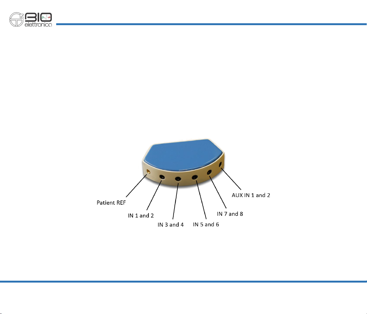
AD8x1SE
This adapter allows the connection of up to 8 electrode pairs through four four-poles 3.5 mm jacks (see Fig. 8.2). The signal
detected from the 16 electrodes feed the positive inputs of the first 16 channels. The patient reference, available on the adapter
as a 2 mm female banana connector, has to be placed using a reference strap or a large electrode to the patient body on a place
without bioelectrical activity.
At the same time, this electrode fixes the standard patient body potential mode to the midpoint of the power supply of
Sessantaquattro and feed the negative inputs of all the channels.
FIG. 8.2:
The AD8x1SE adapter

Sessantaquattro user manual v1.3.2 - April 2020
20
This adapter is intended for the detection of 8 bipolar signals obtained as a difference between each electrode pair. The differences
are estimated from the microcontroller by subtracting, sample by sample, the A/D conversions generated from the channels
corresponding to each electrodes pair. Figure 8.3 shows the 3.5 mm jack pinout to interface the two electrode pairs to the
Sessantaquattro.
Additionally, to the EMG signals, the AD8x1SE allows the connection of two auxiliary signals through a fifth jack connector. This
connector can also provide a 3.3 V output voltage to eventually supply external circuits.
There is no a limit for the current supplied by this output voltage, but it is intended for small loads, in the order of few tens of
milliamps. This voltage is also the voltage used for the internal analog circuits supply, thus, unregulated absorption can generate
noise on the biopotential signals. Figure 8.4 shows the pinout of the auxiliary input connector.
The input swing for the AUX IN signals is ± 3.3 V. Refer to section 8.2 for further details about the AUX IN signals conversion.
Pair 2 – Negative electrode
Pair 1 – Negative electrode
Pair 2 – Positive electrode
Pair 1 – Positive electrode
GND
AUX IN2
AUX IN1
3.3 V
FIG. 8.3:
Four poles 3.5 mm jack connector pinout for the
connection of two electrode pairs to the AD8x1SE adapter
FIG. 8.4:
Four poles 3.5 mm jack connector pinout for the
connection of two auxiliary signals to the AD8x1SE adapter
Table of contents
Other Bioelettronica Amplifier manuals


