Biohort StoreMax 190 User manual

1
BIOHORT Gartengeräte GmbH, A-4120 Neufelden
www.biohort.at
GB
NL
F
I
190 cm x 97 cm x 136 cm
D
„StoreMax 190“
Aufbauanleitung
Assembly manual
Instruction de montage
Montage-instructies
Istruzione di montaggio
bh-StoreMax190 Aufbauanl_zD 26.01.2004 22:00 Uhr Seite 1

2
ATTENTIE:
• De StoreMax niet in elkaar zetten bij wind
• Tijdens de montage en het schoonmaken
werkhandschoenen dragen
• Sommige metalen delen kunnen scherpe
kanten hebben – Gevaar voor verwondingen
• De StoreMax dient stormvast verankerd te
worden
• Het benodigde bevestigingsmateriaal (schroe-
ven en pluggen) vindt u in de plastic zak
ACHTUNG:
• StoreMax nicht bei Wind zusammenbauen
• Unbedingt Arbeitshandschuhe für Montage und
Reinigung verwenden
• Einige Blechteile können scharfkantig sein –
Verletzungsgefahr!
• Sturmfeste Verankerung nicht vergessen!
• Das passende Befestigungsmaterial
(Schrauben+Dübel) finden Sie im Kleinteile-
Päckchen
ATTENTION:
• Don´t attempt to assemble the box on a windy
day
• Wear work gloves when assembling or main-
taining the box
• Some pieces can contain sharp edges
• The box must be anchored to prevent wind
damage
• The belonging clamping material (screws +
dowels) you will find in the small parts package
ATTENTION:
• Ne pas assembler quand il y a du vent
• Portez absolument des gants de travail pour le
montage et le nettoyage
• Certaines tôles peuvent avoir des arêtes
tranchantes – danger de blessures!
• N’oubliez pas l’ancrage contre la tempête!
• Vous trouverez le matériel de fixation (vis et
chevilles) dans le paquet de vis
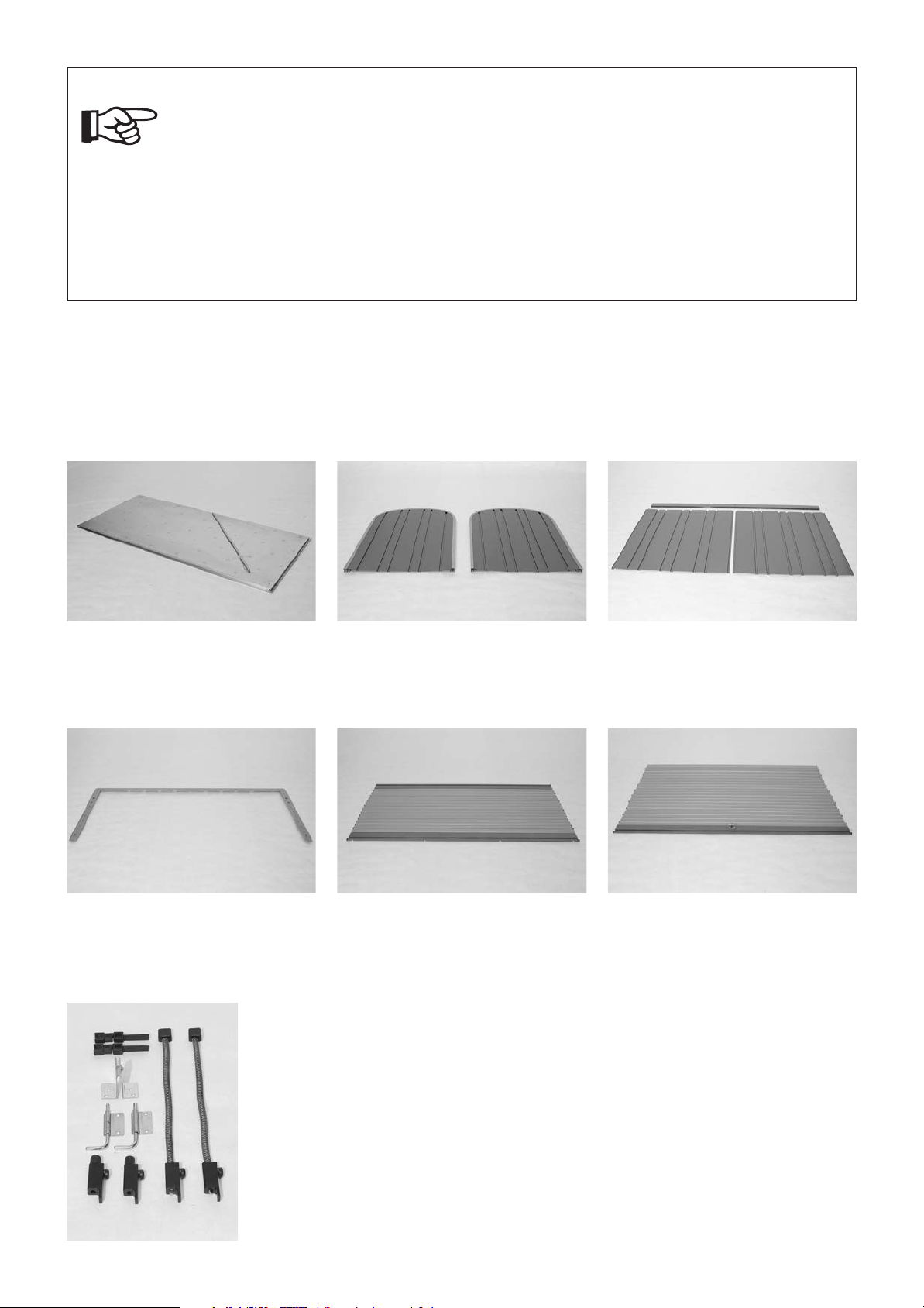
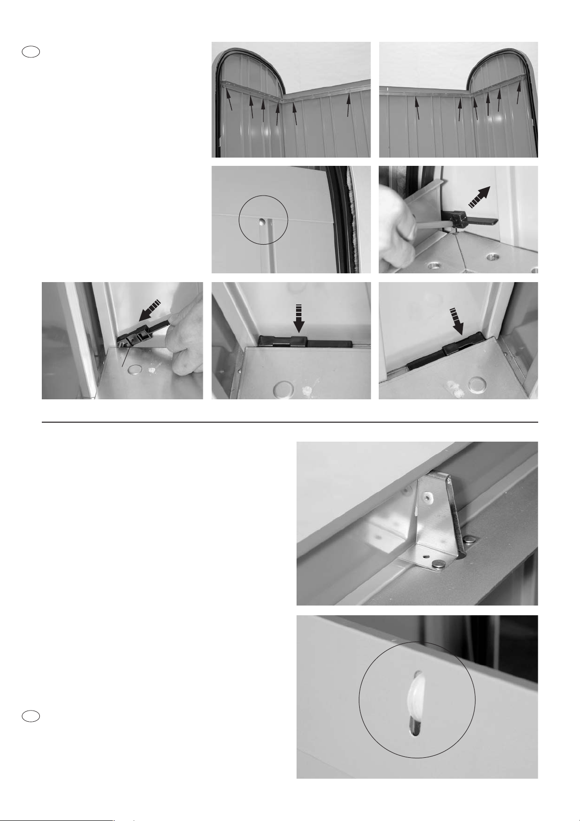
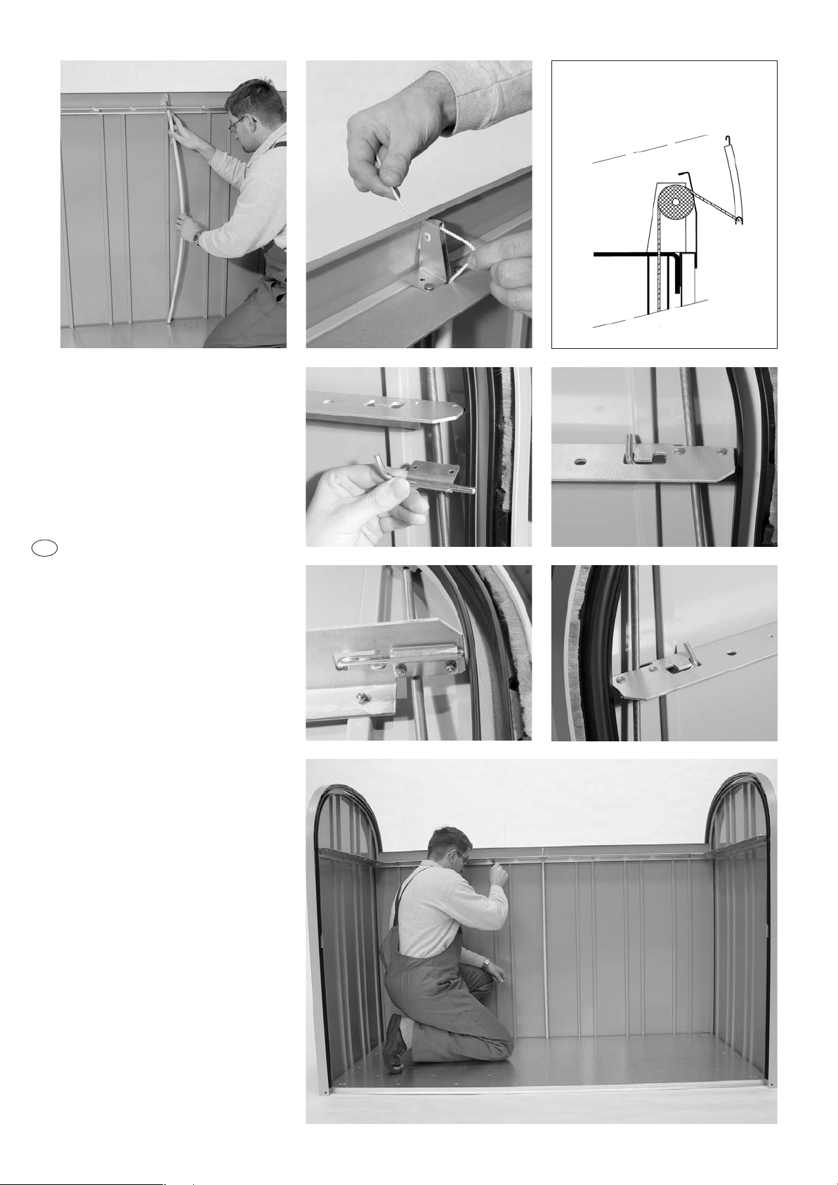
HINWEISE ZUR MONTAGE:
• Für einige Montageschritte benötigen Sie einen Helfer
• Die vorliegende Aufbauanleitung zeigt den Zusammenbau
von „StoreMax 190“, quartz-grau. Die Aufbauanleitung gilt
sinngemäß auch für andere Standardfarben und alle
Sonderlackierungen
• Die Stückliste finden Sie auf den Seiten 14 und 15
• Schraubenmuttern erst am Ende der Montage festziehen!
PFLEGE UND WARTUNG:
• Ölen Sie das Schloss jährlich
• Keine Chemikalien lagern!
ASSEMBLY NOTES:
• The assembly must be carried out by 2 people
• The present erection instruction shows the assembly of
StoreMax 190 quartz-grey. The instruction is accordingly valid
for other standard colors and all special coatings
• A part list is enclosed
• Tighten the nuts not before having finished the assembly
of the box!
CARE & MAINTENANCE:
• Lubricate the lock once a year
• Don´t store chemicals!
REMARQUES CONCERNANT LE MONTAGE:
• L’assemblage doit être effectué de 2 personnes
• Cette instruction de montage décrit l’assemblage d’un
StoreMax 190. Valable par analogie pour les autres couleurs
et le laquage spécial
• Ci-joint un inventaire des pièces
• Ne serrer les écrous à fond qu’à la fin du montage!
ENTRETIEN:
• Graissez la serrure chaque année
• Ne pas stocker de produits chimiques!
MONTAGE-ADVIES:
• Deze montage-instructies hebben betrekking op de monta-ge
van de “StoreMax 190” parelgrijs. Hij geldt vanzelfspre-kend ook
voor alle andere standaard enspeciale kleuren
• Een lijst van de onderdelen is bijgesloten
• De moertjes pas aan het eind van de montage geheel
vastdraaien!
ONDERHOUD:
• Het slot jaarlijks oliân
• Geen chemicaliân opslaan!
GB
D
F
NL
CONSIGLI PER IL MONTAGGIO:
• Le presenti istruzioni di montaggio mostrano il modello
StoreMax 190, colore grigio quarzo. Esse sono valide anche
per tutti gli altri colori standard e tutte le smaltature speciali
• Viene allegata la lista delle parti
• Serrare a fondo i dadi solo a montaggio completato
MANUTENZIONE:
• Lubrificare la serratura una volta all’anno
• Non conservare nel box prodotti chimici
ATTENZIONE:
• Non montare il box con tempo ventoso
• Portare sempre guanti da lavoro per montare
e pulire la casetta
• Qualche componente in lamiera può avere il
bordo tagliente – usare cautela!
• Il box va ancorato al terreno per evitare dan-
neg giamenti
• La minuteria di ancoraggio (viti e tasselli) è imbal
lata nel pacchetto dei piccoli componenti
I
bh-StoreMax190 Aufbauanl_zD 26.01.2004 22:00 Uhr Seite 2

Versteifungsprofil
Stiffening section
Profil de renforcement
Verstevigingsprofiel
Profili di rinforzo
Rolladen vorne
Roller shutter, front part
Volet roulant antérieur
Roldeur voorzijde
Chiusura avvolgibile, parte frontale
Rolladen oben (mit Schloss)
Roller shutter, top part (with lock)
Volet roulant supérieur (avec serrure )
Roldeur bovenkant
Chiusura avvolgibile, parte superiore con
serratura
3
Bodenplatte
Bottom plate
Plaque de fond
Bodemplaat
Pavimento
linke und rechte Seitenwand
Side wall left, side wall right
Parois latérales droite et gauche
Zijwand links, Zijwand rechts
Fianco destro e fianco sinistro
Rückwandbleche (3-teilig)
Rear wall panels (3 parts)
Paroi arrière (3 parties)
Achterwand paneel ( 3-delig)
Pannelli posteriori (tre pezzi)
Feder-Stopper, Gummipuffer-Stopper, Verriegelung,
Umlenkrolle, Distanzteile
Spring-stopper, rubber buffer stopper, locking, guide pulley, distance pieces
Arrêt-ressort, arrêts en caoutchouc, serrure verrouillage, poulie, pièces de distance
Katrol, rubber stoppers, veer stoppers
Puleggia, respingenti di gomma, arresto a molla
Übersicht Teile - Overview of parts - Vue d’ensemble des pièces -
Onderdelen overzicht - Vista d’assieme delle Parti
ACHTUNG: Vergessen Sie nicht auf eine ausreichende Veranke-
rung Ihres „StoreMax 190“ mit den beiliegenden Schrauben und
Dübel. Denken Sie an Stürmböen!!!
ATTENTION: Do not forget to have sufficient anchorage of your “StoreMax 190” using the
enclosed screws and dowels. Consider heavy gusts of wind!!!
ATTENTION: N’oubliez pas un ancrage suffisant de votre «StoreMax 190» à l’aide des vis
et des chevilles jointes – pensez aux rafales de vent!!!
bh-StoreMax190 Aufbauanl_zD 26.01.2004 22:00 Uhr Seite 3

4
Montage der Rückwand: Legen Sie die Bo-
denplatte auf einen ebenen Untergrund. Stel-
len Sie die linke Rückwand wie abgebildet in
das U-Profil an der Rückseite der Bodenplatte. Achten
Sie auf die richtige Positionierung der Rückwand: In-
nenseite = hellgraue Seite, Schlitz (siehe Foto) muss
sich oben/außen befinden. Sichern Sie die Rückwand
mit einer kurzen Niro-Blechschraube an der Boden-
platte. Die rechte Rückwand stellen Sie ebenfalls in das
U-Profil der Bodenplatte.
Die beiden Rückwände werden nun an den halben
Sicken (siehe Detail „C“) auf mittlerer Höhe mit einer
Schraube/Scheibe/Mutter (Scheibe und Mutter innen-
seitig) verbunden – Mutter noch nicht festziehen.
Nun befestigen Sie die beiden Rückwände mit den
kurzen Niro-Blechschrauben am Bodenprofil (insge-
samt 4x – siehe Pfeile).
Rear wall assembly: Place the bottom plate on an even ground.
Then, stick the left rear wall into the U-section on the left side of the
bottom plate (see photos).
Carefully check the right position of the rear wall (inner side = light
grey, slot must be positioned outside/up).
Connect the rear wall and the bottom plate with one short stainless
steel metal screw. Also stick the right rear wall into the U-section of
the bottom plate.
Fix both rear walls in the middle (see detailed illustration „C“) using
one screw, washer and nut (washer and nut inside) – do not secure
the nut yet. Next, secure the wall panels at the bottom plate using
two short stainless steel metal screws (totally 4x – see arrows).
Montage de la paroi arrière: Posez la plaque de fond sur une sur-
face plane. Emboîtez la paroi arrière gauche (L) dans le profil en U
du côté gauche de la plaque de fond. Faites attention au bon po-
sitionnement (voir photos, côté intérieur = côté gris clair, la fente
doit se trouver en haut/à l’extérieur).
Reliez les deux parties comme représenté avec une petite vis in-
oxydable. Fixez de la même façon la paroi arrière droite. Mainte-
nant, assemblez les deux parois arrières comme illustré voir «C»
à l’aide d’une vis / rondelle / écrou (rondelle et écrou à l’intérieur)
du milieu (ne pas encore serrer l’écrou)!
Reliez les deux parois arrières avec la plaque de fond à l’aide des 4
petites vis inoxydables (4 au total – voir flèches)
1.
Zusammenbauschritte - Assembly steps - Etapes d’assemblage -
Stappen van de montage - Sequenza di Montaggio
GB
F
„A”
Detail „A”
„B”
Detail „B”
Detail „C”
bh-StoreMax190 Aufbauanl_zD 26.01.2004 22:00 Uhr Seite 4

5
Montage der Seitenwände: Stecken Sie die
rechte Seitenwand in das U-Profil der rechten
Seite der Bodenplatte. (Achtung: die rechte
Seitenwand erkennen Sie daran, dass die Rollladen-
Bremsfeder an der Vorderseite positioniert ist – siehe
Pfeil). Verbinden Sie die rechte Seitenwand mit der
Rückwand provisorisch (wie abgebildet) mit dem
schwarzen Kunststoffteil (=Montagehilfe, welche später
als Distanzstück für Bodenplatte/Rückwand dient). Jetzt
verschrauben Sie die rechte Seitenwand mit 2 kurzen
Niro-Blechschrauben mit der Bodenplatte. In gleicher
Weise stellen Sie die linke Seitenwand in das U-Profil der
linken Seite der Bodenplatte.
Wiederum sichern Sie diese Seitenwand mit der
schwarzen Montagehilfe wie abgebildet. Auch die
linke Seitenwand verschrauben Sie mit 2 kurzen Niro-
Blechschrauben mit der Bodenplatte. Nun verschrau-
ben Sie die Aluprofile der linken und rechten Seiten-
wände an der Vorderseite mit den langen Niro-Schrau-
ben mit der Bodenplatte.
Ebenso verschrauben Sie die Aluprofile links und rechts
mit den langen Niro-Schrauben an der Hinterseite mit
der Bodenplatte – bitte die hinteren Schrauben noch
nicht festziehen!
Zuletzt stecken Sie das Rückwand-Aufsetzblech wie
dargestellt auf die Rückwand – bitte diesen Teil noch
nicht verschrauben!
2.
R
R
Vorderseite
front side
antèrieur
Rückseite
rear side
l’envers
bh-StoreMax190 Aufbauanl_zD 26.01.2004 22:00 Uhr Seite 5

6
GB
F
Side wall assembly: Stick the right side wall into the U-section on
the right side of the bottom plate (you can identify the right side wall
by the roller shutter-stopper positioned on the front side – see ar-
rows). Link the right side wall and the rear wall using the black plas-
tic part (assembly help which will later serve as distance piece for
bottom plate/rear wall).
Now fix the right side wall with the bottom plate, using two short
stainless steel metal screws. Stick the left side wall the same way into
the U-section on the left side of the bottom plate. Once again se-
cure the side wall with the black plastic part as illustrated. Fix the left
side wall with the bottom plate, again using two short stainless steel
metal screws.
Now connect the aluminium sections of the left and the right side
walls to the front side of the bottom plate using long stainless steel
metal screws. Do the same procedure at the back side of the bot-
tom plate – please to not yet secure the screws at the back!
Finally, attach the small wall panel to the rear wall – but do not yet
fix the two parts!
Montage des parois latérales: Emboîtez la paroi latérale droite
dans le profil en U du côté droit de la plaque de fond. Faites atten-
tion au bon positionnement (vous pouvez identifier la paroi droite
par l’arrêt ressort qui se trouve en avant – voir flêche). Reliez la paroi
latérale droite et la paroi arrière à l’aide de la petite pièce en plas-
tique noir (= aide de montage qui servira comme pièce de dis-
tance entre la paroi arrière et la plaque de fond).
Maintenant, fixez la paroi latérale droite et la plaque de fond à
l’aide de 2 petites vis inoxydables. Posez de la même façon la paroi
latérale gauche dans le profil en U du côté gauche de la
plaque de fond. Utilisez le tube en plastique noir comme repré-
senté. Puis, fixez aussi la paroi latérale gauche et la plaque de fond
à l’aide de 2 petites vis inoxydables.
Reliez en avant les profils en aluminium des parois latérales droites
et gauches et la plaque de fond à l’aide de 4 longues vis inoxydab-
les. Faites la même chose en arrière de la plaque de fond – ne ser-
rez pas encore les vis!
Finalement, emboîtez la petite paroi arrière additionnelle sur la pre-
mière – mais ne serrez pas encore les vis en arrière!
R
R
R
LL
LL
R
R
Feder
spring
ressort
Feder
spring
ressort
bh-StoreMax190 Aufbauanl_zD 26.01.2004 22:00 Uhr Seite 6

7
Vorne links
front side left
avant gauche
Vorne rechts
front side right
avant droit
hinten
rear
l’envers
hinten
rear
l’envers
Einbau des Versteifungsprofils / Einbau der
Distanzstücke: Nehmen Sie wie abgebildet
das Versteifungsprofil, führen Sie es vorsichtig in
die Box ein und verschrauben Sie es links und rechts an
den Enden (siehe Pfeile) handfest nur mit je einer
Schraube/Scheibe/Mutter an den Seitenwänden.
Nun schwenken Sie das Versteifungsprofil rückwärts und
nach oben und verschrauben Sie es zuerst links und
rechts hinten mit der Rückwand mit je einer
Schraube/Scheibe/Mutter. Damit ist das Versteifungs-
profil vorläufig gesichert. Nun verschrauben Sie das
Versteifungsprofil mit den Seitenwänden und mit der
Rückwand an allen übrigen Stellen (siehe Pfeile – ins-
gesamt 12 mal). Jetzt entfernen Sie im linken und
rechten Eck die schwarzen Montagehilfen, welche
nun ihre eigentliche Verwendung als Distanzstücke be-
kommen. Dazu legen Sie diese schwarzen Kunststoff-
teile (Distanzstücke) links und rechts unten wie abgebil-
det zwischen Bodenplatte und Rückwand bei den lan-
gen Niro-Schrauben ein.
Nun kann die Verschraubung der linken und rechten
Aluprofile auf der Rückseite mit der Bodenplatte fest
angezogen werden.
Mounting of stiffener section and distance pieces: Take the stif-
fener section and carefully insert it into the box. Fix it on the left and
right sides (see arrows) with one screw, washer, and nut each at the
side walls. Then, move the stiffener section backwards on top and fix
it left and right to the rear wall using one screw, washer, and nut
each. The stiffener section is now provisionally secured. Next, secure
the stiffener section with the side walls and the rear wall (see arrows
– totally 12 times).
Please remove the black plastic parts from the left and right corner.
They will now be used – as originally intended – as distance pieces.
Insert the plastic parts as illustrated left and right between bottom
plate and rear wall at the long stainless steel metal screws. You can
now finally connect the left and right aluminium profiles to the bot-
tom plate and secure the screws.
3.
GB
bh-StoreMax190 Aufbauanl_zD 26.01.2004 22:00 Uhr Seite 7

8
Einbau der Umlenkrolle und der Verriege-
lungen: Befestigen Sie die Umlenkrolle wie ab-
gebildet mittig auf der Hinterseite des Verstei-
fungsprofils mit 2 Schrauben/Scheiben/ Muttern. Die
Muttern können Sie bereits fest anziehen. Lösen Sie nun
das Plastikrohr mit der innenliegenden Zugfeder von
der Bodenplatte.
Führen Sie das Ende der weißen Nylonschnur durch die
mittige Öffnung des Versteifungsprofils (direkt unter der
Umlenkrolle) und stecken Sie das Plastikrohr in diese
Öffnung. Fädeln Sie die Nylonschnur wie dargestellt ein
und lassen Sie das Ende der Nylonschnur hinten hin-
ausragen.
Montieren Sie rechts und links vorne am Versteifungs-
profil die Verriegelungsstifte samt Führungsplättchen
mit je zwei Schrauben/Scheiben/Muttern. Nun ziehen
Sie alle Muttern mit dem beiliegenden Steckschlüssel
M7 und alle Niro-Blechschrauben mit einem Kreuz-
schraubendreher fest an. Achten Sie dabei, dass die
Box eben steht!
Mounting of guide pulley and locking pins: Secure the guide
pulley onto the stiffener section (in the middle of the long side, as il-
lustrated) with two screws, washers and nuts. You can already se-
cure the nuts.
Next, separate the plastic tube from the bottom plate with the inner
spring. Put the end of the white string directly next to the guide pul-
ley from underneath through the stiffener section and fit the plastic
4.
Fixation du profil de renforcement et
des pièces de distance: Prenez comme
représenté le profil de renforcement et po-
sitionnez-le à l’intérieur du Store Max. Fixez
les parois latérales et le profil de renforce-
ment sur les côtés droit et gauche (voir flè-
ches) avec une vis/rondelle/écrou. Tournez
le profil de renforcement en arrière et en
haut et reliez-le et la paroi arrière à gau-
che et à droit à l’aide d’une vis/rondelle/
écrou. Le profil de renforcement est fixé
provisoirement.
Maintenant reliez le profil de renforcement,
les parois latérales et la paroi arrière au to-
tal 12 fois (voir flèches).
Détachez les tubes en plastique noir pour
les utiliser comme pièces de distance. Puis,
mettez les pièces de distance à gauche et
à droit entre la plaque de fond et la paroi
arrière (placez-les chez les 4 longues vis in-
oxydables).
Maintenant, vous pouvez serrer les profils en
aluminium gauche et droit en arrière de la
plaque de fond.
F
Rückseite
rear panel
l’envers
Rückseite
rear side
l’envers
Distanzstück
distance piece
pièce de distance
GB
Links hinten
rear side left
l’envers gauche
Rechts hinten
rear side light
l’envers droit
bh-StoreMax190 Aufbauanl_zD 26.01.2004 22:00 Uhr Seite 8

9
part into the stiffening section.
Put the white nylon string over the pulley
and leave the end of the string protrude at
the back.
Fix the locking pins at the front left and right
side of the stiffener section using two
screws, washers and nuts for each pin. Now
secure all nuts using the enclosed socket
wrench M7 and all stainless steel screws
using a Phillips screwdriver. Take care that
the box is placed on a plane floor!
Fixation de la poulie et des renforce-
ments: Fixez tout d’abord la poulie sur l’ar-
rière du profil de renforcement en utilisant
2 vis/rondelles/écrous. Vous pouvez déjà
serrer les écrous. Détachez alors le tube en
plastique contenant le ressort de traction
de la plaque de fond.
Faites passer le bout du fil blanc directe-
ment au niveau de la poulie à travers le
profil de renforcement en passant par le
bas et emboîtez le tube en plastique dans
le profil de renforcement. Faites passer la fi-
celle en nylon comme représenté sur la
roue et à travers la paroi arrière et laissez
prendre la ficelle pour le moment.
Fixez maintenant les tiges de verrouillage
du profil de renforcement (à gauche et à
droit) à l’aide de deux vis/rondelles/écrous.
Serrer tous les écrous à l’aide de la clé à
canon M7 et tous les vis inoxydables à
l’aide d’un tournevis. Veillez à ce que votre
«StoreMax 190» soit sur une surface plane.
Verriegelung rechts
locking right
verrouillage droit
Verriegelung links
locking left
verrouillage gauche
Skizze Schnurführung
Section string guiding
Dessin passage de la ficelle
F
bh-StoreMax190 Aufbauanl_zD 26.01.2004 22:00 Uhr Seite 9

10
Einführen der Rollläden: Legen Sie die Box
vorsichtig nach vorne. Führen Sie den „vorde-
ren“ Rollladen (= ohne Schloss!) mit der Außen-
seite nach oben und mit den weißen Gummipuffern
voran (siehe Foto) behutsam in die innere (=untere)
Führungsnut des Aluminiumbogens ein.
Achten Sie dabei, dass die seitlichen, schwarzen Kunst-
stoffgleitrollen der Aluminiumlamellen nicht verspießen.
Schieben Sie den Rollladen vorsichtig nach vorne und
lassen Sie ihn bis auf den Boden gleiten.
Nehmen Sie nun den „oberen“ Rollladen (=mit
Schloss!) und führen Sie ihn mit der Außenseite nach
oben und dem Schloss voran behutsam in die äußere
(=obere) Führungsnut des Aluminiumbogens ein.
Achten Sie beim Einführen wiederum darauf, dass die
Kunststoffgleitrollen der Lamellen nicht beschädigt wer-
den. Schieben Sie den Rollladen vorsichtig nach vorne
und sorgen Sie vor, dass das Schloss beim Auftreffen
auf dem Boden nicht beschädigt wird.
Roller shutter installation: Place the box on the front side. Care-
fully slide the front roller shutter (without lock!) into the grooves of the
aluminium arches with the outer side facing up and the white rub-
ber buffer-stoppers going in first (see photos!). Pay attention that the
black plastic gliders on the sides of the aluminium slats are firmly in
place and do not stick out.
Carefully push the roller shutter towards the front and let it roll down
to the ground. Then take the upper roller shutter (with lock!) and in-
sert into the outer grooves of the aluminium arches with the outer
side facing up and the lock towards the front. Carefully move the
roller shutter towards the front and be aware of not damaging the
lock on the ground.
Montage des volets roulants: Faites basculer le coffre vers l’avant,
c’est-à-dire que la paroi arrière est en haut. Introduisez le volet an-
térieur (= sans serrure), face extérieure vers le haut, les petits amor-
tisseurs en plastique blanc en premier, précautionneusement dans
la rainure interne du profil en aluminium. Faites attention à ce que
les embouts en plastique noir des lamelles en aluminium soient
bien positionnés et ne ressortent pas. Introduisez le volet roulant tout
doucement et laissez-le glisser jusqu’au sol.
Prenez maintenant le volet supérieur (= avec serrure) et introduisez-
le face extérieure vers le haut et la serrure en premier dans la rai-
nure externe du profil en aluminium. Faites-le glisser prudemment
vers l’avant et faites attention à ce que la serrure ne soit pas en-
dommagée par le sol.
5.
GB
F
Untere Führungsnut
inner groove
rainure interne
bh-StoreMax190 Aufbauanl_zD 26.01.2004 22:00 Uhr Seite 10

11
Montage der hinteren Rollladen-Stopper:
Die beiden Feder-Stopper werden an der inne-
ren (=unteren) Führungsnut wie abgebildet
eingesteckt und kraftvoll bis zum Anschlag nach unten
gedrückt. Dies gilt für die linke und rechte Seite spiegel-
gleich. Zur Sicherung werden die beiden Stopper mit je
einer kurzen Niro-Blechschraube am Alumi-
niumprofilbogen festgeschraubt. Die beiden Gummi-
Stopper werden wie dargestellt an der äußeren
(=oberen) Führungsnut eingesteckt und wieder bis zum
Anschlag kraftvoll nach unten geschoben.
Die Gummi-Stopper werden ebenfalls links und rechts
mit je einer kurzen Niro-Schraube gesichert.
Jetzt stellen Sie Ihren „StoreMax 190“ wieder auf.
Assembly of the back roller shutter-stoppers: Put both spring-
stoppers onto the inner grooves as illustrated and push them down
as far as possible. Tightly secure the stoppers to the arched alumi-
nium section using one stainless steel screw for each side. Then, put
both rubber stoppers onto the outer grooves and push again hard
to fit them in. Secure both rubber stoppers as well with the short
stainless steel screws.
Now stand the “Store Max 190” up once more.
Montage des arrêts arrières du volet roulant: Les deux arrêt-res-
sorts sont emboîtés dans la rainure interne (voir photo), exercez une
pression vers le bas jusqu’au butoir. Faites la même chose à gauche
et à droit. Par sécurité, les deux arrêts seront fixés par une vis inoxyd-
able au profil en aluminium.
Les deux arrêts en caoutchouc seront emboîtés dans la rainure ex-
terne et à nouveau enfoncés jusqu’au butoir par une forte pression
vers le bas. Ils seront également fixés par une vis.
Maintenant relevez votre «StoreMax 190».
6.
GB
F
Schloss
lock
serrure
Obere Führungsnut
outer groove
rainure externe
1.
2.
3.
bh-StoreMax190 Aufbauanl_zD 26.01.2004 22:00 Uhr Seite 11

12
Fertigstellung und Funktionsprüfung:
Der Rollladen ist in geschlossenem Zustand. An
der Rückseite fädeln Sie die weiße Nylonschnur
wie dargestellt durch die Bohrung der hintersten La-
melle und machen an der rot markierten Stelle einen
festen Achterknoten. Auf einem ebenen Untergrund
prüfen Sie die Leichtgängigkeit der Rollläden.
Die Rollladenführungen sind werkseitig bereits gefettet.
Zum späteren Nachfetten der Führungen liegt eine
kleine Dose Vaseline bei.
Die Federstopper sind so berechnet, dass sie ein sanf-
tes , kindersicheres Abstoppen der Rollläden gewähr-
leisten und gleichzeitig das Öffnen bzw. Schließen er-
leichtern.
Der Gleitstab des Federstoppers (auf der Rückseite)
kann bei Bedarf gefettet werden. Prüfen Sie die Funk-
tion des Zylinderschlosses und der Verriegelungsstifte.
Ölen Sie das Schloss mindestens jährlich mit einem
dünnflüssigen Öl.
Completion and function check: The “Store Max 190” is in a clo-
sed position and stands on an even ground.
On the back side insert the white nylon string into the hole of the slat
furthest back and make a tight knot on the place marked in red.
Check the smooth running of the roller shutter. The shutter guides
are made of special, easy-gliding plastic. In order to facilitate the
use of the roller shutter, we recommend you to grease the shutter
guides with the Vaseline which you find enclosed.
The spring stoppers guarantee the roller shutters to stop in a smooth,
child-proof way, and they enable an easy opening and closing.
The gliding rod of the spring-stopper (on the back) should be oiled
when necessary.
Check the operation of the cylinder locks and locking pin. Oil the
cylinder lock at least once a year with a thin, liquid oil.
7.
GB
3.
1.
2.
bh-StoreMax190 Aufbauanl_zD 26.01.2004 22:00 Uhr Seite 12

13
Contrôle de fonctionnalité et finissage: Le StoreMax 190 est
fermé. Enfilez la ficelle en nylon à travers le trou de la dernière la-
melle comme représenté et faites un nœud à l’endroit marqué en
rouge. Mettez votre «StoreMax 190» sur une surface plane et con-
trôlez la facilité d’utilisation des volets roulants.
Les glissières du volet roulant sont en plastique spécial ayant la pro-
priété de glisser et n’ont pas besoin d’être huilées ni d’être graissées.
Les arrêt-ressorts sont calculés de telle façon qu’un arrêt du volet
roulant est assuré en douceur.
En plus, pour la sécurité des enfants, ils facilitent également ouver-
ture et fermeture. Le pied coulissant des arrêt-ressorts peut être
huilé si nécessaire. Contrôlez le fonctionnement de la serrure cylin-
drique et des tiges de verrouillage. Graissez la serrure cylindrique
avec une huile fluide.
F
Skizze Verankerung
Section anchorage
Dessin ancrage
Raffigurazione dell’ancoraggio
Senkkopfschraube
Screw
Vis noyée
Vite
Kunststoffdübel
Dowel
Cheville
Tassello
ACHTUNG: Vergessen Sie nicht auf
eine ausreichende Verankerung Ihres
„StoreMax 190“ mit den beiliegenden
Schrauben und Dübel. Denken Sie an
Stürmböen!!!
ATTENTION: Do not forget to have sufficient
anchorage of your “StoreMax 190” using the
enclosed screws and dowels. Consider heavy
gusts of wind!!!
ATTENTION: N’oubliez pas un ancrage suffisant
de votre «StoreMax 190» à l’aide des vis et
des chevilles jointes – pensez aux rafales de
vent!!!
bh-StoreMax190 Aufbauanl_zD 26.01.2004 22:00 Uhr Seite 13

bh-StoreMax190 Aufbauanl_zD 26.01.2004 22:00 Uhr Seite 14

bh-StoreMax190 Aufbauanl_zD 26.01.2004 22:00 Uhr Seite 15

Zubehör für den StoreMax 190
Optional accessory for StoreMax 190
Accessoire optionnel pour StoreMax 190
Gerätehaus „Europa“
Garden shed „Europa“
Abri de jardin « Europa »
Regaleset inkl. 2 Regalsteher (Art.-Nr. 74020)
Shelf-bases incl. 2 shelf sections (order-no: 74020)
Jeu d’étagères comprenant 2 fonds + support (No. com-
mande: 74020)
Zwischenboden inkl. 8 Stützen, auch als 2-teiliges Regal
verwendbar (Art.-Nr. 75020)
Intermediate floor incl. 8 supports, can also be used as a 2 part
shelf (order-no: 75020)
Sol intermédiaire comprenant 8 fixations, peut aussi être utilisé
comme 2 étagères (No. commande 75020)
ohne Dekoration
without decoration
sans décoration
Geräteschrank
Equipment locker
Armoire à outils
FreizeitBox
Leisure time box
Coffre de jardin
CoverBox
Dustbin storage
Coffrage pour la poubelle
GB
F
Biohort Gartengeräte GmbH
A-4120 Neufelden, Pürnstein 43
www.biohort.at
BH-408-1A-01.04-F!
Qualitätskontrolle / Quality-Control / Contrôle-Qualité
Kontrollnummer:
Inspection-number:
Contrôle-Qualité:
Bei Reklamationen bitte anführen: Kontrollnummer und Artikelnum-
mer des reklamierten Teils.
In case of complaint please indicate the inspection number and the
number of the item, which is the subject of the complaint.
Pour toutes réclamations: prière de joindre le numéro de contrôle et le
numéro d´article de la pièces litigieuse.
D
Weitere Biohort-Produkte
Further Biohort-products
Autres produits de Biohort
GB
F
D
bh-StoreMax190 Aufbauanl_zD 26.01.2004 22:00 Uhr Seite 16
Other manuals for StoreMax 190
2
Other Biohort Storage Bin manuals