BIOS DVPro T10B3 User manual
DVPro High Performance Storage
System User Manual
----------------------------------------------------------------------------
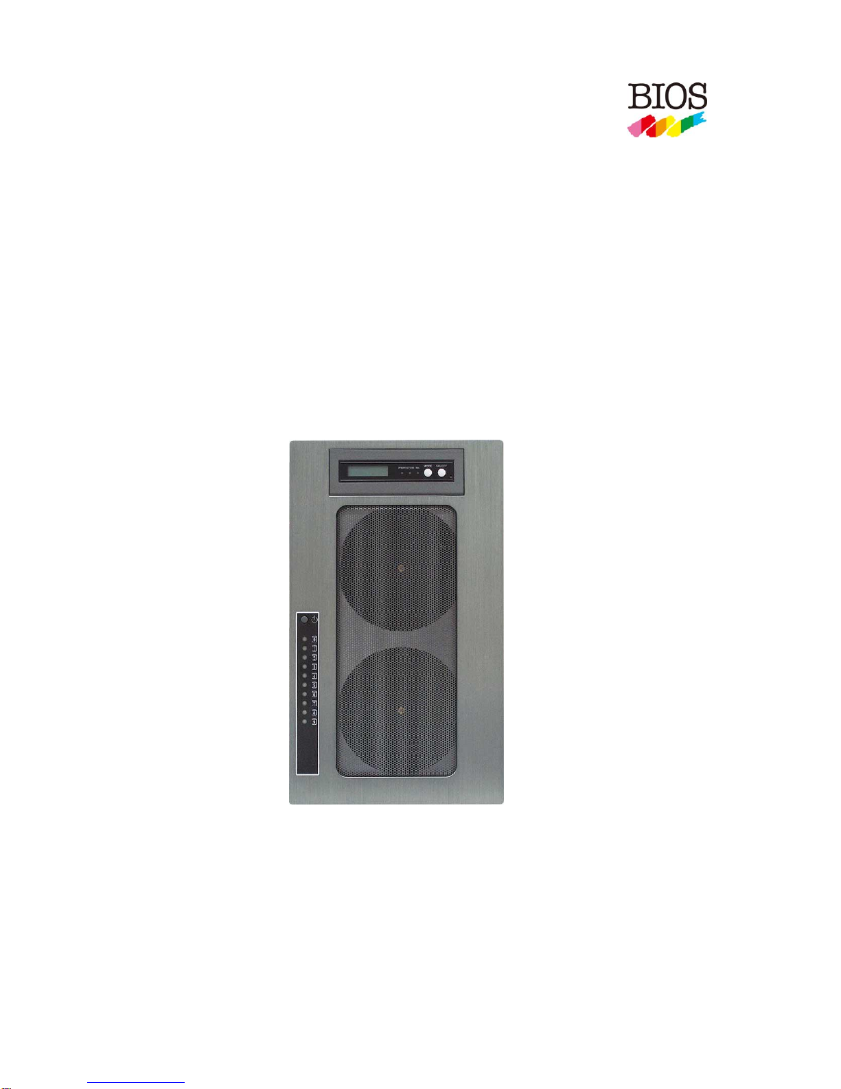
T10B3
-eSATA6G and USB3 HOST MODEL-
[ User Manual ]
Version 1.0
----------------------------------------------------------------------------

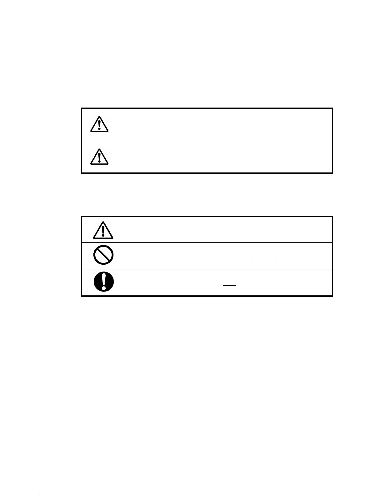
Safety Warning
In order to avoid injury to oneself, please heed the following instructions.
■The following indications explain the degree of physical danger possible by ignoring the proper usage
directions.
■The various types of warning symbols are listed in the following picture.
This symbol means that you should pay extra caution.
This symbol indicates something you absolutely must not do.
This symbol indicates something you must do.
WARNING
This symbol and waning is used to indicate sections
that may result in a serious injury or even death.
This symbol and caution is used to indicate
sections that only pose a risk of minor injury or
physical damage.
CAUTION
M

BIOS CORPORATION
-1-
Precautions
This user manual contains features, functions, setup, and warnings, so please read this manual prior to use
our product.
・If any material in this manual is not clear, please contact vender whom you purchased from.
・The information in this manual is subject to change without prior notice.
・It is prohibited to reproduce any part of this manual in any form or by any means without prior written
permission of the manufacturer and the author.
・Manufacturer assumes no liability or responsibility for any errors that may appear in this manual. In case
issue arised please contact us or vender whom you purchased from.
・All trademarks stated in this manual belong to the properties of their respective owners.

DVT10B3
-2-
‥‥‥‥‥‥‥‥‥‥‥‥‥‥‥‥‥‥‥‥‥‥‥‥‥‥‥‥‥‥‥‥‥‥‥‥‥‥‥‥‥‥‥‥‥‥‥‥
‥‥‥‥‥‥‥‥‥‥‥‥‥‥‥‥‥‥‥‥‥‥‥‥‥‥‥‥‥‥‥‥‥‥‥‥‥‥‥‥‥‥‥‥‥‥‥‥
‥‥‥‥‥‥‥‥‥‥‥‥‥‥‥‥‥‥‥‥‥‥‥‥‥‥‥‥‥‥‥‥‥‥‥‥‥‥‥‥‥‥‥‥‥‥‥‥
‥‥‥‥‥‥‥‥‥‥‥‥‥‥‥‥‥‥‥‥‥‥‥‥‥‥‥‥‥‥‥‥‥‥‥‥‥‥‥‥‥‥‥‥‥‥‥‥
‥‥‥‥‥‥‥‥‥‥‥‥‥‥‥‥‥‥‥‥‥‥‥‥‥‥‥‥‥‥‥‥‥‥‥‥‥‥‥‥‥‥‥‥‥‥‥‥
‥‥‥‥‥‥‥‥‥‥‥‥‥‥‥‥‥‥‥‥‥‥‥‥‥‥‥‥‥‥‥‥‥‥‥‥‥‥‥‥‥‥‥‥‥‥‥‥
‥‥‥‥‥‥‥‥‥‥‥‥‥‥‥‥‥‥‥‥‥‥‥‥‥‥‥‥‥‥‥‥‥‥‥‥‥‥‥‥‥‥‥‥‥‥‥‥
‥‥‥‥‥‥‥‥‥‥‥‥‥‥‥‥‥‥‥‥‥‥‥‥‥‥‥‥‥‥‥‥‥‥‥‥‥‥‥‥‥‥‥‥‥‥‥‥
‥‥‥‥‥‥‥‥‥‥‥‥‥‥‥‥‥‥‥‥‥‥‥‥‥‥‥‥‥‥‥‥‥‥‥‥‥‥‥‥‥‥‥‥‥‥‥‥
‥‥‥‥‥‥‥‥‥‥‥‥‥‥‥‥‥‥‥‥‥‥‥‥‥‥‥‥‥‥‥‥‥‥‥‥‥‥‥‥‥‥‥‥‥‥‥‥
‥‥‥‥‥‥‥‥‥‥‥‥‥‥‥‥‥‥‥‥‥‥‥‥‥‥‥‥‥‥‥‥‥‥‥‥‥‥‥‥‥‥‥‥‥‥‥‥
‥‥‥‥‥‥‥‥‥‥‥‥‥‥‥‥‥‥‥‥‥‥‥‥‥‥‥‥‥‥‥‥‥‥‥‥‥‥‥‥‥‥‥‥‥‥‥‥
‥‥‥‥‥‥‥‥‥‥‥‥‥‥‥‥‥‥‥‥‥‥‥‥‥‥‥‥‥‥‥‥‥‥‥‥‥‥‥‥‥‥‥‥‥‥‥‥
‥‥‥‥‥‥‥‥‥‥‥‥‥‥‥‥‥‥‥‥‥‥‥‥‥‥‥‥‥‥‥‥‥‥‥‥‥‥‥‥‥‥‥‥‥‥‥‥
‥‥‥‥‥‥‥‥‥‥‥‥‥‥‥‥‥‥‥‥‥‥‥‥‥‥‥‥‥‥‥‥‥‥‥‥‥‥‥‥‥‥‥‥‥‥‥‥
‥‥‥‥‥‥‥‥‥‥‥‥‥‥‥‥‥‥‥‥‥‥‥‥‥‥‥‥‥‥‥‥‥‥‥‥‥‥‥‥‥‥‥‥‥‥‥‥
‥‥‥‥‥‥‥‥‥‥‥‥‥‥‥‥‥‥‥‥‥‥‥‥‥‥‥‥‥‥‥‥‥‥‥‥‥‥‥‥‥‥‥‥‥‥‥‥
‥‥‥‥‥‥‥‥‥‥‥‥‥‥‥‥‥‥‥‥‥‥‥‥‥‥‥‥‥‥‥‥‥‥‥‥‥‥‥‥‥‥‥‥‥‥‥‥
‥‥‥‥‥‥‥‥‥‥‥‥‥‥‥‥‥‥‥‥‥‥‥‥‥‥‥‥‥‥‥‥‥‥‥‥‥‥‥‥‥‥‥‥‥‥‥‥
‥‥‥‥‥‥‥‥‥‥‥‥‥‥‥‥‥‥‥‥‥‥‥‥‥‥‥‥‥‥‥‥‥‥‥‥‥‥‥‥‥‥‥‥‥‥‥‥
‥‥‥‥‥‥‥‥‥‥‥‥‥‥‥‥‥‥‥‥‥‥‥‥‥‥‥‥‥‥‥‥‥‥‥‥‥‥‥‥‥‥‥‥‥‥‥‥
‥‥‥‥‥‥‥‥‥‥‥‥‥‥‥‥‥‥‥‥‥‥‥‥‥‥‥‥‥‥‥‥‥‥‥‥‥‥‥‥‥‥‥‥‥‥‥‥
‥‥‥‥‥‥‥‥‥‥‥‥‥‥‥‥‥‥‥‥‥‥‥‥‥‥‥‥‥‥‥‥‥‥‥‥‥‥‥‥‥‥‥‥‥‥‥‥
‥‥‥‥‥‥‥‥‥‥‥‥‥‥‥‥‥‥‥‥‥‥‥‥‥‥‥‥‥‥‥‥‥‥‥‥‥‥‥‥‥‥‥‥‥‥‥‥
‥‥‥‥‥‥‥‥‥‥‥‥‥‥‥‥‥‥‥‥‥‥‥‥‥‥‥‥‥‥‥‥‥‥‥‥‥‥‥‥‥‥‥‥‥‥‥‥

BIOS CORPORATION
-3-
Table of Contents
Precautions..........................................................................................................................1
Table of Contents ................................................................................................................3
Chapter 1. Outline.............................................................................................................4
Features......................................................................................................................................................... 4
Functions........................................................................................................................................................ 4
Packing Contents........................................................................................................................................... 5
Hardware Components.................................................................................................................................. 5
Connection..................................................................................................................................................... 8
Chapter 2. Setup and Monitor .........................................................................................10
2.1 Setup Overview................................................................................................................................ 10
2.2 LCD Toggle rolling setup flowchart................................................................................................... 10
2.3 Introduction of Parameters Setup .....................................................................................................11
2.4 RAID Operational Parameters ......................................................................................................... 12
2.5 Product Information and Background Parameters........................................................................... 18
2.5.1 Method to setup background parameters .............................................................................. 18
2.5.2 Parameter Confirmation......................................................................................................... 24
2.6 Web-based Monitor and Setup via Ethernet.................................................................................... 27
2.6.1 Main Screen of Web GUI ....................................................................................................... 28
2.6.2 Introduction of Monitor Mode.................................................................................................. 29
2.6.3 Management Mode Login....................................................................................................... 32
2.6.4 Setup of email notification...................................................................................................... 34
2.6.5 Mail Format............................................................................................................................. 35
2.6.6 Conditions of Mail Notification................................................................................................ 36
2.6.7 SNMP Setup........................................................................................................................... 36
2.6.8 Additional Parameters Setup.................................................................................................. 38
2.7 Setup Mode (Array Parameters Setting).......................................................................................... 39
2.8 Host LAN Configuration ................................................................................................................... 44
2.8.1 IP Setup for Windows............................................................................................................. 44
2.8.2 IP Setup for Linux................................................................................................................... 46
2.8.3 IP Setup for MAC OS X.......................................................................................................... 47
Chapter 3 Format...............................................................................................................50
3.1 Linux................................................................................................................................................. 50
3.2 Windows 7........................................................................................................................................ 52
3.3 Other OSs ........................................................................................................................................ 57
Appexdix A - MBR of different Operating Systems............................................................58
Appexdix B –Error Message shown on LCD.....................................................................59

DVT10B3
-4-
Chapter 1. Outline
Features
●Support up to 10 Hot-swap SATA HDD (Hard Disk Drive)
● Support different RAID modes including RAID 6, RAID 5, RAID 3, RAID 1, RAID 0, RAID10
●Dual Host Interface: eSATA3 (6Gbps) and USB 3.0 (5Gbps)
● Original FPGA RAID 6 Engine with real time parity generation and high speed DMA switching
● Spot error recovery greatly reduces HDD error and rebuild probability
●Automatic Rebuild at adjustable Rebuild Rate
●Maintain same performance upon drive failure and little impact at recovery(RAID 3, 5, 6)
● LCD and keypad operation for status monitoring and system configuration
● Web GUI status monitoring and system configuration
Functions
● Two independent or single LUN support for eSATA and USB
● Configurable Write Cache Mode
● Configurable Verify Mode
● Data Read Ahead Size
● Write Retry Mode
● Buffer Segment Size Adjustment
● Starting time of Retry
● Sequential List Size
● Time out Interval for Low Speed Drive Detection
● Power On Standby time
● Drive Ready Waiting Time
● Cache Memory Check Interval
● HDD Patrol Time and Mode
<Auxiliary Functions>
● Performance (Data Transfer Speed) Display on LCD
● Event display on LCD
●Email Notification Support
● Web-based Status Monitor
● SNMP notification

BIOS CORPORATION
-5-
Packing Contents
DVT10B3: Storage sytesm
AC Power Cord
USB3 Cable: 1 meter USB-IF certified
eSATA Cable: 1 meter eSATA cable
Screws: 50 pcs of screws and Quick Installation Guide
CD : User manual (this file)
Hardware Components
< Front View>
⑧
①
④
⑥
⑦
②
③
⑤

DVT10B3
-6-
⑭
< Rear View >
< Side View >
⑨
⑩
⑫
⑪
⑬
⑮
BIOS CORPORATION
-7-
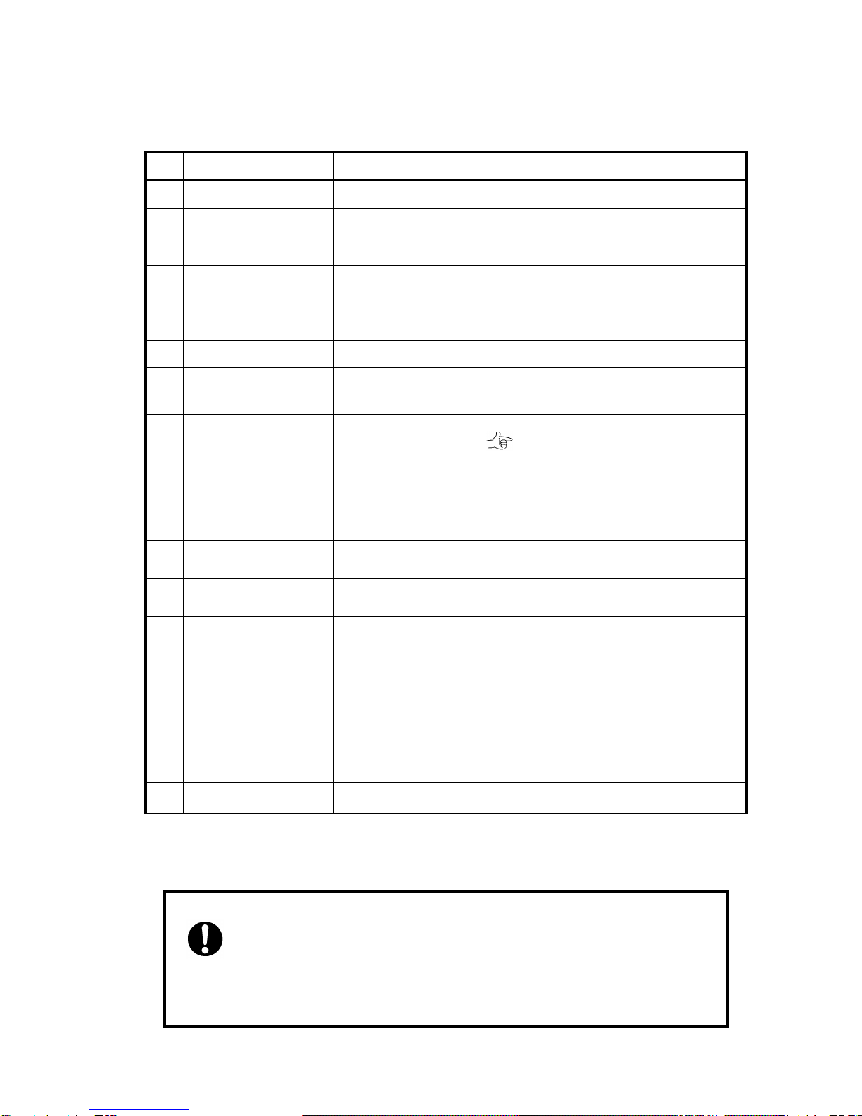
No.
Name
Function Explanation
①
POWER Switch
Power ON /OFF Switch
②
HDD Access / FAIL
LED
BLUE Flash upon access; Orange ON indicates an error
When「RAID-x RECOVERING 0%」shown on LCD, the FAIL LED on
means the HDD is under rebuilding
③
POWER LED
Power ON LED indicator
④
ACCESS LED
Host Access LED indicator
⑤
FAIL LED
A controller error LED indicator
⑥
MODE Button
1)Parameter Initialization(Power on Initialization)
2)Configure parameters 「See Chapter 2」
3)Stop buzzer alarm(Buzzer stopped immediately by pushing one
time)
⑦
SELECT Button
Setup Parameter
⑧
LCD Display
Message display screen. Show status of the system
Show parameters while doing configuration
⑨
Power Input
AC Inlet
⑩
eSATA3 Connector
eSATA host connector
⑪
USB3 Connector
USB3 host connector
⑫
Ethernet Port
RJ45 Fast Ethernet port for Web GUI management
⑬
Fan Module
Fan 1
⑭
Fan Module
Fan 2
⑮
Drive Module
Disk Drive module 0 (to 9).Upper left one is number 0, and right is 1
● Both eSATA and USB3 cannot be applied to same LUN at the same
time. For simulateneous usage of eSATA and USB3, two LUN mapping and
SWAP mode should be configured.

DVT10B3
-8-
Connection
<Steps for eSATA connection>
1. Basic connection
eSATA or USB 3→Host Computer
①Connect eSATA Cable or USB3 cable from host to the system. (included in the package)
②To use web-based GUI, connect Ethernet cable between LAN connector and host
2. Dual Connection
Connect both eSATA and USB3 cables from host to the system
①Configure LUN size as any kind of two LUNs and LUN mode as “LUN Swapped…”
First LUN will be mapped to eSATA and second LUN to USB3. For example, users can create
LUN Size as ( 64GB+ALL ). A 64GB LUN will be mapped to eSATA and the rest of capacity will
be mapped to USB3 host.
②To use web-based GUI, connect Ethernet cable between LAN connector and host

BIOS CORPORATION
-9-
‥‥‥‥‥‥‥‥‥‥‥‥‥‥‥‥‥‥‥‥‥‥‥‥‥‥‥‥‥‥‥‥‥‥‥‥‥‥‥‥‥‥‥‥‥‥‥‥
‥‥‥‥‥‥‥‥‥‥‥‥‥‥‥‥‥‥‥‥‥‥‥‥‥‥‥‥‥‥‥‥‥‥‥‥‥‥‥‥‥‥‥‥‥‥‥‥
‥‥‥‥‥‥‥‥‥‥‥‥‥‥‥‥‥‥‥‥‥‥‥‥‥‥‥‥‥‥‥‥‥‥‥‥‥‥‥‥‥‥‥‥‥‥‥‥
‥‥‥‥‥‥‥‥‥‥‥‥‥‥‥‥‥‥‥‥‥‥‥‥‥‥‥‥‥‥‥‥‥‥‥‥‥‥‥‥‥‥‥‥‥‥‥‥
‥‥‥‥‥‥‥‥‥‥‥‥‥‥‥‥‥‥‥‥‥‥‥‥‥‥‥‥‥‥‥‥‥‥‥‥‥‥‥‥‥‥‥‥‥‥‥‥
‥‥‥‥‥‥‥‥‥‥‥‥‥‥‥‥‥‥‥‥‥‥‥‥‥‥‥‥‥‥‥‥‥‥‥‥‥‥‥‥‥‥‥‥‥‥‥‥
‥‥‥‥‥‥‥‥‥‥‥‥‥‥‥‥‥‥‥‥‥‥‥‥‥‥‥‥‥‥‥‥‥‥‥‥‥‥‥‥‥‥‥‥‥‥‥‥
‥‥‥‥‥‥‥‥‥‥‥‥‥‥‥‥‥‥‥‥‥‥‥‥‥‥‥‥‥‥‥‥‥‥‥‥‥‥‥‥‥‥‥‥‥‥‥‥
‥‥‥‥‥‥‥‥‥‥‥‥‥‥‥‥‥‥‥‥‥‥‥‥‥‥‥‥‥‥‥‥‥‥‥‥‥‥‥‥‥‥‥‥‥‥‥‥
‥‥‥‥‥‥‥‥‥‥‥‥‥‥‥‥‥‥‥‥‥‥‥‥‥‥‥‥‥‥‥‥‥‥‥‥‥‥‥‥‥‥‥‥‥‥‥‥
‥‥‥‥‥‥‥‥‥‥‥‥‥‥‥‥‥‥‥‥‥‥‥‥‥‥‥‥‥‥‥‥‥‥‥‥‥‥‥‥‥‥‥‥‥‥‥‥
‥‥‥‥‥‥‥‥‥‥‥‥‥‥‥‥‥‥‥‥‥‥‥‥‥‥‥‥‥‥‥‥‥‥‥‥‥‥‥‥‥‥‥‥‥‥‥‥
‥‥‥‥‥‥‥‥‥‥‥‥‥‥‥‥‥‥‥‥‥‥‥‥‥‥‥‥‥‥‥‥‥‥‥‥‥‥‥‥‥‥‥‥‥‥‥‥
‥‥‥‥‥‥‥‥‥‥‥‥‥‥‥‥‥‥‥‥‥‥‥‥‥‥‥‥‥‥‥‥‥‥‥‥‥‥‥‥‥‥‥‥‥‥‥‥
‥‥‥‥‥‥‥‥‥‥‥‥‥‥‥‥‥‥‥‥‥‥‥‥‥‥‥‥‥‥‥‥‥‥‥‥‥‥‥‥‥‥‥‥‥‥‥‥
‥‥‥‥‥‥‥‥‥‥‥‥‥‥‥‥‥‥‥‥‥‥‥‥‥‥‥‥‥‥‥‥‥‥‥‥‥‥‥‥‥‥‥‥‥‥‥‥
‥‥‥‥‥‥‥‥‥‥‥‥‥‥‥‥‥‥‥‥‥‥‥‥‥‥‥‥‥‥‥‥‥‥‥‥‥‥‥‥‥‥‥‥‥‥‥‥
‥‥‥‥‥‥‥‥‥‥‥‥‥‥‥‥‥‥‥‥‥‥‥‥‥‥‥‥‥‥‥‥‥‥‥‥‥‥‥‥‥‥‥‥‥‥‥‥
‥‥‥‥‥‥‥‥‥‥‥‥‥‥‥‥‥‥‥‥‥‥‥‥‥‥‥‥‥‥‥‥‥‥‥‥‥‥‥‥‥‥‥‥‥‥‥‥
‥‥‥‥‥‥‥‥‥‥‥‥‥‥‥‥‥‥‥‥‥‥‥‥‥‥‥‥‥‥‥‥‥‥‥‥‥‥‥‥‥‥‥‥‥‥‥‥
‥‥‥‥‥‥‥‥‥‥‥‥‥‥‥‥‥‥‥‥‥‥‥‥‥‥‥‥‥‥‥‥‥‥‥‥‥‥‥‥‥‥‥‥‥‥‥‥
‥‥‥‥‥‥‥‥‥‥‥‥‥‥‥‥‥‥‥‥‥‥‥‥‥‥‥‥‥‥‥‥‥‥‥‥‥‥‥‥‥‥‥‥‥‥‥‥
‥‥‥‥‥‥‥‥‥‥‥‥‥‥‥‥‥‥‥‥‥‥‥‥‥‥‥‥‥‥‥‥‥‥‥‥‥‥‥‥‥‥‥‥‥‥‥‥
‥‥‥‥‥‥‥‥‥‥‥‥‥‥‥‥‥‥‥‥‥‥‥‥‥‥‥‥‥‥‥‥‥‥‥‥‥‥‥‥‥‥‥‥‥‥‥‥
‥‥‥‥‥‥‥‥‥‥‥‥‥‥‥‥‥‥‥‥‥‥‥‥‥‥‥‥‥‥‥‥‥‥‥‥‥‥‥‥‥‥‥‥‥‥‥‥
DVT10B3
-10 -
Chapter 2. Setup and Monitor
2.1 Setup Overview
To simplify the process of setup, DVPro is designed to support all of setup options from front panel LCD
and button operation. The default RAID level is RAID6 for highest reliability. To prevent malfunction,
parametners cannot be changed at normal operation mode. Critical parameters include number of drive,
capacity, and RAID mode should be set up before you started to work with the unit. Default parameter if
any is followed with “*” sign
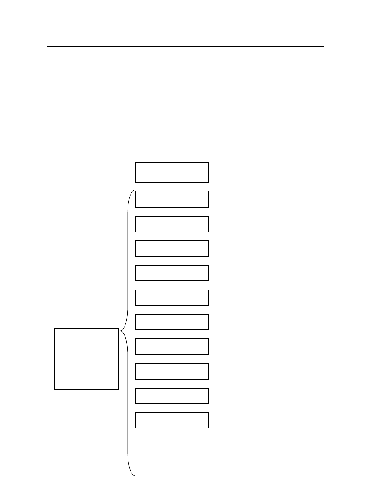
2.2 LCD Toggle rolling setup flowchart
ARRAY PARAMETERS
SETTING!
:Initial Display
↓
Disk Size Setup
:Hard Disk Capacity Setup
↓
RAID MODE Setup
:RAID Mode Setup
↓
Drive Mode
:Number of Drive Setup
↓
SECTOR SIZE Setup
:SECTOR size setup
↓
LUN SIZE Setup
:LUN size setup
↓
LUN MODE Setup
:LUN mode setup
↓
Parity STRIPE Size
:STRIPE size setup
↓
SATA/USB HOST Setup
:SATA/USB host Enable/Disable
↓
Recovery Rate Setup
:Recovery/Rebuild rate setup
↓
Cache Size Setup
:Cache size setup
↓
Most of cases, users do
not need to change the
default setting.
Please make sure you
understand the function
before making any
change.

BIOS CORPORATION
-11 -
Write Pending Setup
:Write delay time setup
↓
Write Verify Setup
:Write verify setup
↓
Read Ahead Setup
:Read ahead size setup
2.3 Introduction of Parameters Setup
This section will explain the general parameters setup process.
To start with new configuration, the system has to enter Parameter Setup mode. Please press and hold
both “Mode”and “Select”buttons for more than 3 seconds while turning on power. The LCD should show
message as below indicating the system in Parameter Setup mode.
ARRAY PARAMETERS
SETTING!
You can then start to modify each parameter under this mode.
General usage of Buttons:
MODE Button: To rotate among Parameter items
SELECT Button: Select the parameter for change
●Enter Parameters Setting mode
:MODE Button +SELECT Button + Power On
●Rotate among Setup items
:MODE Button
●Setup parameters
:SELECT Button
By pressing MODE and SELECT button at the same time after modification, the selected parameters will
be written to internal non-volatile memory then the change will be effective at next power on.
When you successfully change the parameter, you will see
POWER DOWN
PLEASE!
Shutdown and power on or press SELECT button for 3 seconds.
If you power down before saving to memory the settings will be reverted to the way they were upon the
last save.
● Saving the change
:① MODE +SELECT Button (Save)
②Shutdown and power on or Press SELECTButton 3 sec
● Cancel the change
:Power off while doing change

DVT10B3
-12 -
After a new configuration completed, hold down the Mode button at next power on at the same time for
system initialization. (Notice: this will initialize controller based on configured parameters. This action will
force failed drive or rebuilding status to become “Normal”. Please DO NOT do this if your system was in
degraded mode, and need to be recovered.) After power on, LCD should show its RAID mode and
“Normal”status.
RAID-6
NORMAL
2.4 RAID Operational Parameters
This section explains each RAID parameter and the associated function of DVPro system.
Ps. Please take a memo if you changed parameters different from its default value. You
can follow the method described on「Parameter Confirmation」section to read its
value.
Disk Size Setup
DISK Size
xxB
This is to specify the capacity of the drive you want to use. The size will be applied to all drives.
(Usually the system was configured with exact drive size of inserted disks. You should not change the drive
size unless you want to reconfigure and change it.)
Parameter
Function
Memo
Test 1GB
Set DISK Size as 1GB (Test only)
120GB, 160GB, 250GB,
400GB, 500GB, 750GB,
1TB, 2TB, 3TB, 4TB
Set Disk Size as
● Please do not change the default setting
If actual drive size was smaller than setup value, error such as「ONE
DOWN L」,「SYSTEM DOWN L」might happen and buzzer will be fired.
RAID Mode Setup
RAID MODE
RAID-6
RAID mode selection, supported RAID MODE are
CAUTION
M

BIOS CORPORATION
-13 -
RAID 6, RAID 5, RAID 3, RAID 1, RAID 0, RAID 1 Three Drive, RAID 10, Single Drive
RAID 1 Three Drive means same data is written to three drives and read might be from any drive.
RAID10 works as a pair of ‘Drive 0,1’‘Drive 2,3’, ‘Drive 4,5’etc.
Drive Mode Setup
DRIVE MODE
6
Setup number of drives in used
Parameter
Function
Memo
DRIVE MODE 3
3 Disks(DATA+PARITY)Mode
DRIVE MODE 4
4 Disks(DATA+PARITY)Mode
DRIVE MODE 5
5 Disks(DATA+PARITY)Mode
DRIVE MODE 6
6 Disks(DATA+PARITY)Mode
DRIVE MODE 7
Below is for 10 drive model
DRIVE MODE 8
DRIVE MODE 9
DRIVE MODE 10
Default
Sector Size Setup
SECTOR SIZE
512B
512B, 4KB
This is to setup sector size of disk. For new Advanced Format HDD, you need to set up 4KB for better
performance on sequential Write access. Please check with your drive vendor for the sector size.
LUN Size Setup
LUN SIZE
Max 2TB
Parameter
Function
Memo
LUN SIZE
FULL
Configure all capacities to Single LUN size.
Depend on host operating system, LUN over 2TB size might not
be recognized.
LUN SIZE
MAX 2TB
One LUN only and size is set to 2TB as some Operating
systems only support less than 2TB LUN size
LUN SIZE
1/2 DIVISION
Two LUNs each with half of total capacities will be assigned
LUN SIZE
64GB + ALL
Set up one LUN as 64GB and the rest of all as 2nd LUN (or 2nd
LUN maximum is 2TB.)

DVT10B3
-14 -
64GB + Max2TB
LUN SIZE
256GB+ALL
1TB+ALL
2TB+ALL
Set up one LUN as 256GB, 1TB or 2TB and the rest of all
capacities as 2nd LUN
Note: For LUN mapping to host port, please refer to LUN MODE parameter for details.
LUN MODE Setup
LUN DIRECT
No BIAS
Parameter
Function
Memo
LUN DIRECT
No BIAS
LUN Direct :Both eSATA and USB3 host will be mapped to first
LUN
Default
LUN SWAPPED
No BIAS
LUN SWAPPED: First host will be mapped to eSATA and 2nd
LUN will be mapped to USB3.
LUN DIRECT
for MBR(-1)
※Please refer to below explanation
LUN SWAPPED
for MBR(-1)
※Please refer to below explanation
LUN DIRECT
for MBR(+1)
※Please refer to below explanation
LUN SWAPPED
for MBR(+1)
※Please refer to below explanation
※Sector management of RAID are different between [NO BIAS] and [for MBR(-1) or (+1)]
Depend on host OS used, the beginng sector address of disk partition is different. And the setting
might affect the performance. The setting should not be changed during operation and disk Format is
necessary if changed. Please refer to MBR related information in Appendix A.
Parity Stripe Width Setup
PARITY STRIPE
2 MB/DRIVE
Choose stripe width of RAID-5/6 LUN
Parameter
Function
Memo
PARITY STRIPE
2MB/DRIVE
1MB/DRIVE
256KB/DRIVE
128KB/DRIVE
Setup stripe width of each drive channel.
When the host issues a command, and the parity is to be
written, the command is divided up into two or more
operations.A relatively big stripe width is setup to reduce the
overhead of continuous operation.
Default
2 MB/DRIVE
BIOS CORPORATION
-15 -
The bigger size of stripe width, faster transfer speed can be
achieved for sequential read or write. Usually「2MB/ DRIVE」
setup will give a good performance but it depends on the host
application.
Setup of eSATA Host
eSATA3 Host
Enabled
Parameter
Function
Memo
eSATA3 Host
Enabled
Enable eSATA Host Channel
Default
eSATA3 Host
Disabled
Disable eSATA Host Channel
Setup of USB3 Host
USB3 Host
Disabled
Parameter
Function
Memo
USB3 Host
Enabled
Enable USB3 Host Channel
USB3 Host
Disabled
Disable USB3 Host Channel
Default
※When both eSATA3 and USB3 hosts are enabled, make sure LUN MODE set to “Swapped”
Recovery Rate Setup
RECOVER RATE
5Min. /GB
Recovery (Rebuild) operations utilize free time between host data access without interrupting the current
host application.
Therefore data read/write priority can be adjusted through different recovery rate setting.
User can choose the timing to execute recovery operations as below.
Parameter
Function
Memo
RECOVER
WAIT
TIME 0 Sec
Recovery request will be processed immediately between host
commands. Recovery will always be processed therefore host
access will be slow down. Select this mode if you want the
recovery have high priority.

DVT10B3
-16 -
RECOVER
WAIT
TIME 0.1 Sec
Continuous host commands will be processed first. Recovery
operation will be taken care when the interval between host
commands longer than 0.1 sec. The following host command has
to wait till one recovery task completed except READ/WRITE or
READ Cache command which will be executed immediately.
RECOVER
WAIT
TIME 1 Sec
This can be used when host access are not concentrated.
The wait interval following the last host command is 1 sec. On this
mode, the recovery operation will not be processed if the host
commands are continuous with less than 1 sec internal.
RECOVER
WAIT
TIME 10 Sec
Usually this should not be used.
Probably this mode can be applied if there is very little host
access.
RECOVER
RATE
2Min./GB
5Min./GB
10Min./GB
20Min./GB
This is to assign the recovery time for 1GB capacity despite of
interval to wait between host commands.
There is possibility 1GB recovery cannot be completed
within assigned interval.
Default
5Min./GB
Cache Size Setup
CACHE SIZE
512MB
This parameter is only for DEBUG usage. Users should NOT alter this setting.
Parameter
Function
Memo
CACHE SIZE
64MB
128MB
256MB
512MB
「Cache Buffer Error」will be shown if the selected cache
size not matched the installed cache memory
Default
512MB
Write Cache Mode setup
WRITE ALL
PENDING 0.1Sec
The controller needs more time than writing to single drive to generate parity while doing RAID-3/5/6
WRITE. Therefore Write Cache is enabled in such situation.
This parameter defines the timing of flushing cache contents into disks.
Parameter
Function
Memo
WRITE MODE
WAITING
Under this setting, the Write operation will not be acknowledged
as “Completed” till data is written into disks. This means no
caching is used during data write. The performance is slower
compared to 「WRITE MODE PENDING」mode. READ speed is
not affected.
Write
Through
BIOS CORPORATION
-17 -
WRITE MODE
BUFFERD
Write command is acknowledged as “Completed” right after data
written into cache, and cached data starts to be moved into disks
at the same time.
Write Back
WRITE MODE
PENDING
0.1Sec
After caching the first host WRITE, the cache content will only be
flushed into disk if there is more than 0.1 sec host idle or cache
threshold is met. When doing sequential writes, cache will be
filled by multiple write command and data can be written once to
save total write time.
Default
WRITE MODE
PENDING
1 Sec
Similar to PENDING 0.1 sec, the wait interval is one second.
Verify Mode Setup
VERIFY WAIT
READ aft WRITE
Verify Mode allows you to setup the action for ATA WRITE VERIFY command. “No Verify”will take
‘WRITE VERIFY’command as a simple ‘WRITE’without waiting verification to be completed.
Upon READ request after a WRITE command, “NO READ aft WRITE”, means to use cached content to
respond a READ command after WRITE. “READ aft WRITE”means cache data was disgarded and
controller has to read data from disk
Parameter
Function
Memo
VERIFY
WAITRead aft
Write
The Write Verify command cannot be completed at the time data
written into cache. It has to wait till Verification completed. And
the written data in cache will be discarded. The data will be read
from the disk when a read request comes in.
Default
VERIFY
NO READ aft
WRT
The Write Verify command cannot be completed at the time data
written into cache. It has to wait till Verification completed. And
use the written data in cache for following READ command
usage.
NO VERIFY
Read aft Write
Write Verify command is treated as Write without verification. And
the written data in cache will be discarded. The data will be read
from the disk when a read request comes in.
NO VERIFY
NO READ aft
WRITE
Write Verify command is treated as Write without verification. And
use the written data in cache for following READ command
usage.
Read Ahead Setup
READ AHEAD
64 KB
This is to set size of data to prefetch into cache for read operation.
Parameter
Function
Memo
READ AHEAD
0 KB
Do not do read ahead.
You might like to use this setting if read data is frequenty changed
Table of contents
Other BIOS Storage manuals

Popular Storage manuals by other brands


Panasonic
Panasonic AG-MSU10P operating instructions

Maker Factory
Maker Factory MAKEVMA304 user manual

Dell
Dell Data Domain DD9500 Hardware overview and installation guide

Dyness
Dyness POWERCUBE Series user manual

Dell
Dell EqualLogic FS7610 Installation and setup guide

Infortrend
Infortrend EonNAS 1000 Series manual


