BIOS BR256 User manual

BR256(eSATA+USB2.0)model取扱説明書
-0 -
Best
Energy
and Space Saving Best RAID
Portable RAID6, 2.5”HDD
×
6
・
Desktop Model
----------------------------------------------------------------------------
BR256
-eSATA+USB3.0 model -
【User Manual 】
Revision 1.01f
----------------------------------------------------------------------------

BIOS CORPORATION
-1 -
Safety Warning
■In order to avoid injury to oneself, equipment, and others, please heed the following instructions.
■The following indications explain the degree of physical danger possible by ignoring the proper usage
directions.
The various types of warning symbols are listed in the following picture.
(The following provide examples of the warning drawings.)
This symbol means that you should pay extra attention.
This symbol indicates something you absolutely must not do.
This symbol indicates necessary actions you should take.
WARNING
This symbol is used to indicate sections that may
result in a serious injury or even death.
This symbol is used to indicate sections that might
pose a risk of minor injury or physical damage.
CAUTION
M

BR256(eSATA+USB3.0)model User Manual
-2 -
Prefix
Thank you for choosing our product: Best RAID 256 eSATA+USB3.0 (BR256 hereunder).
This user manual contains features, functions, setup, and warnings, so please read this manual prior to use
our product.
If any material in this manual is not clear, please contact manufacturer or vender where it was purchased.
●The information in this manual is subject to change without prior notice.
●It is prohibited to reproduce any part of this manual in any form or by any means without prior written
permission of the manufacturer and the author.
●Manufacturer assumes no liability or responsibility for any error that may appear in this manual. In case
issue raised please contact manufacturer or vender where this product was purchased.
●All trademarks stated in this manual are the properties of their respective owners.

BIOS CORPORATION
-3 -
③Pull out the lever and hold the
canister to remove HDD module
③Insert the key and turn it
clockwise to lock the
module.
①Insert the key into the lock
hole and turn the key
counterclockwise.
②Push the lever of
canister
①Insert the HDD module
②Push the module into the
enclosure and close the lever
HDD Installation
■Install and Remove HDD Module
①Before you start any operation, please make sure HDDs are installed properly into the BR256
enclosure
②An alarming beep sound will be turned on and caused error if right number of HDD module was not
installed properly
③The system can be used only if the Array parameters have been set up properly.
■Remove HDD Module
■Install HDD Module
There are 4 screw holes on each HDD module. Use screws in accessory pack to screw HDD on the module.

BR256(eSATA+USB3.0)model User Manual
-4 -
Precautions for Product Usage
■Treatment
●Don’t open up the cabinet.
You can be electrocuted.
●Don’t take it apart.
There is a chance to cause fire or injury
●Don’t modify.
There is a chance of fire.
●Don’t open the fan cover
There is a chance of injury
●Make sure to hold the plug when inserting or removing power cable.
There is a risk of electrocution.
●Don’t pull on the cable itself.
There is a chance of fire.
●Never operate unless the power plug is fully inserted.
It may short out and generate excessive heat, causing risk for a fire.
●Never insert or remove the cable with wet hands.
You may be electrocuted.
●Don’t remove the drive unit with your fingernails.
There is a risk of injury.
●When inserting disks don’t put your fingers in the unit case.
There is a risk of injury.
Don’t
CAUTION
M
Don’t
WARNING

BIOS CORPORATION
-5 -
●When removing the drive unit, be sure to use both hands.
You may drop it, causing injury.
●Never shut off the power while the drive is being accessed.
It may cause abnormal operation.
●Never remove the disk unit while it is being accessed.
It may cause abnormal operation.
●Use the original packing when transporting the unit.
It may fall and be damaged by shocks and impact.
●Keep your hands and fingers away from the fan when the case
is opened.
There is a risk of electrocution, fire, and injury.
●Don’t rub on edge of metal chassis.
There is a risk of injury.
●Don’t step on the unit.
There is a risk of injury and breakdown of the product.
●You cannot change the order of the drives once the RAID mode has been established
Please use the six drives in the order that they were installed at time of RAID creation.
●Please be sure to make proper backups of all data periodically
We do not guarantee data stored on HDDs. There might be risk due to software error or mishandling
causing data lost or broken. It is always recommended to back up your data periodically.
●Never use volatile chemicals (such as White Gasoline) or paint thinner
It may cause damage to the color or shape of the item.
If it does get dirty, please clean with a soft cloth and alcohol or soap.
●The unit is sensitive to sudden changes in temperature or humidity
If the unit runs overheat, please be sure to cease operation until the conditions return to normal.
Don’t
CAUTION
M

BR256(eSATA+USB3.0)model User Manual
-6 -
■Placement
●Always use two hands when moving or transporting unit.
Injury can be caused if the item is dropped.
●Place the unit in an area that can sufficiently support its weight.
There is a risk of injury.
●Use a three-pronged outlet.
There is a risk of electrocution.
●Don’t use in places of extreme heat.
There is a risk of fire.
● Don’t use in very dusty or damp places.
There is a risk of fire.
●Don’t place in slant or unstable places.
It may fall and break, and may cause injury.
● Never use with more than the rated voltage.
There is a risk of electrocution.
● Don’t use the cable in anything but the approved power terminal.
There is a risk of injury.
● Don’t attempt to damage, repair, or burn the cable in any way.
If the power cable becomes damaged there is a risk of fire or electrocution.
● Don’t place the item in very hot places or in direct sunlight.
The room’s temperature may rise causing risk of damage.
●Never let the power cord get near a heater.
The coating on the cord may melt causing risk of a fire or electrocution.
Don’t
CAUTION
M
WARNING
BIOS CORPORATION
-7 -
●Turn the power switch off while connecting power cord.
There is a risk of electrocution.
●Remove the power plug upon any malfunction or breakdown.
There is a severe risk of fire or damage if you see smoke or smell any
strange scents coming from the unit. Power down at once and contact the
store where unit was purchased from.
●Never let the unit be near any magnets or equipment containing
magnets.
You may lose data from the hard disk.
● Do not leave the HDD module unlock
There is risk that HDD module falls out of the enclosure
●Never place the unit in any bags or containers containing
liquids.
There is a risk of fire inside the unite, or electrocution
●Keep the unit away from any shocks or vibrations.
The disk may sustain damage.
● Please do not use the unit while another high-power unit is on the same power
circuit.
● Do not use the unit in areas of high heat or humidity.
● Keep the unit away from televisions, radios, speakers, or any unit containing a
magnetic field.
● Don’t use the unit in any areas where liquid may get inside of it.
If liquid ever gets inside the case, remove the power cord at once.
Don’t
WARNING

BR256(eSATA+USB3.0)model User Manual
-8 -
‥‥‥‥‥‥‥‥‥‥‥‥‥‥‥‥‥‥‥‥‥‥‥‥‥‥‥‥‥‥‥‥‥‥‥‥‥‥‥‥‥‥‥‥‥‥‥‥
‥‥‥‥‥‥‥‥‥‥‥‥‥‥‥‥‥‥‥‥‥‥‥‥‥‥‥‥‥‥‥‥‥‥‥‥‥‥‥‥‥‥‥‥‥‥‥‥
‥‥‥‥‥‥‥‥‥‥‥‥‥‥‥‥‥‥‥‥‥‥‥‥‥‥‥‥‥‥‥‥‥‥‥‥‥‥‥‥‥‥‥‥‥‥‥‥
‥‥‥‥‥‥‥‥‥‥‥‥‥‥‥‥‥‥‥‥‥‥‥‥‥‥‥‥‥‥‥‥‥‥‥‥‥‥‥‥‥‥‥‥‥‥‥‥
‥‥‥‥‥‥‥‥‥‥‥‥‥‥‥‥‥‥‥‥‥‥‥‥‥‥‥‥‥‥‥‥‥‥‥‥‥‥‥‥‥‥‥‥‥‥‥‥
‥‥‥‥‥‥‥‥‥‥‥‥‥‥‥‥‥‥‥‥‥‥‥‥‥‥‥‥‥‥‥‥‥‥‥‥‥‥‥‥‥‥‥‥‥‥‥‥
‥‥‥‥‥‥‥‥‥‥‥‥‥‥‥‥‥‥‥‥‥‥‥‥‥‥‥‥‥‥‥‥‥‥‥‥‥‥‥‥‥‥‥‥‥‥‥‥
‥‥‥‥‥‥‥‥‥‥‥‥‥‥‥‥‥‥‥‥‥‥‥‥‥‥‥‥‥‥‥‥‥‥‥‥‥‥‥‥‥‥‥‥‥‥‥‥
‥‥‥‥‥‥‥‥‥‥‥‥‥‥‥‥‥‥‥‥‥‥‥‥‥‥‥‥‥‥‥‥‥‥‥‥‥‥‥‥‥‥‥‥‥‥‥‥
‥‥‥‥‥‥‥‥‥‥‥‥‥‥‥‥‥‥‥‥‥‥‥‥‥‥‥‥‥‥‥‥‥‥‥‥‥‥‥‥‥‥‥‥‥‥‥‥
‥‥‥‥‥‥‥‥‥‥‥‥‥‥‥‥‥‥‥‥‥‥‥‥‥‥‥‥‥‥‥‥‥‥‥‥‥‥‥‥‥‥‥‥‥‥‥‥
‥‥‥‥‥‥‥‥‥‥‥‥‥‥‥‥‥‥‥‥‥‥‥‥‥‥‥‥‥‥‥‥‥‥‥‥‥‥‥‥‥‥‥‥‥‥‥‥
‥‥‥‥‥‥‥‥‥‥‥‥‥‥‥‥‥‥‥‥‥‥‥‥‥‥‥‥‥‥‥‥‥‥‥‥‥‥‥‥‥‥‥‥‥‥‥‥
‥‥‥‥‥‥‥‥‥‥‥‥‥‥‥‥‥‥‥‥‥‥‥‥‥‥‥‥‥‥‥‥‥‥‥‥‥‥‥‥‥‥‥‥‥‥‥‥
‥‥‥‥‥‥‥‥‥‥‥‥‥‥‥‥‥‥‥‥‥‥‥‥‥‥‥‥‥‥‥‥‥‥‥‥‥‥‥‥‥‥‥‥‥‥‥‥
‥‥‥‥‥‥‥‥‥‥‥‥‥‥‥‥‥‥‥‥‥‥‥‥‥‥‥‥‥‥‥‥‥‥‥‥‥‥‥‥‥‥‥‥‥‥‥‥
‥‥‥‥‥‥‥‥‥‥‥‥‥‥‥‥‥‥‥‥‥‥‥‥‥‥‥‥‥‥‥‥‥‥‥‥‥‥‥‥‥‥‥‥‥‥‥‥
‥‥‥‥‥‥‥‥‥‥‥‥‥‥‥‥‥‥‥‥‥‥‥‥‥‥‥‥‥‥‥‥‥‥‥‥‥‥‥‥‥‥‥‥‥‥‥‥
‥‥‥‥‥‥‥‥‥‥‥‥‥‥‥‥‥‥‥‥‥‥‥‥‥‥‥‥‥‥‥‥‥‥‥‥‥‥‥‥‥‥‥‥‥‥‥‥
‥‥‥‥‥‥‥‥‥‥‥‥‥‥‥‥‥‥‥‥‥‥‥‥‥‥‥‥‥‥‥‥‥‥‥‥‥‥‥‥‥‥‥‥‥‥‥‥
‥‥‥‥‥‥‥‥‥‥‥‥‥‥‥‥‥‥‥‥‥‥‥‥‥‥‥‥‥‥‥‥‥‥‥‥‥‥‥‥‥‥‥‥‥‥‥‥
‥‥‥‥‥‥‥‥‥‥‥‥‥‥‥‥‥‥‥‥‥‥‥‥‥‥‥‥‥‥‥‥‥‥‥‥‥‥‥‥‥‥‥‥‥‥‥‥
‥‥‥‥‥‥‥‥‥‥‥‥‥‥‥‥‥‥‥‥‥‥‥‥‥‥‥‥‥‥‥‥‥‥‥‥‥‥‥‥‥‥‥‥‥‥‥‥
‥‥‥‥‥‥‥‥‥‥‥‥‥‥‥‥‥‥‥‥‥‥‥‥‥‥‥‥‥‥‥‥‥‥‥‥‥‥‥‥‥‥‥‥‥‥‥‥
‥‥‥‥‥‥‥‥‥‥‥‥‥‥‥‥‥‥‥‥‥‥‥‥‥‥‥‥‥‥‥‥‥‥‥‥‥‥‥‥‥‥‥‥‥‥‥

BIOS CORPORATION
-9 -
Table of Contents
Safety Warning....................................................................................................................1
Prefix ..............................................................................................................................2
HDD Installation...................................................................................................................3
Precautions for Product Usage............................................................................................4
Table of Contents ................................................................................................................9
Chapter 1. BR256 Outline...............................................................................................11
1.1 Features ............................................................................................................................................11
1.2 Function............................................................................................................................................ 12
1.3 RAID Mode....................................................................................................................................... 13
1.4 Contents of Packing......................................................................................................................... 15
1.5 Name and Function of each part...................................................................................................... 16
1.6 Connection ....................................................................................................................................... 18
1.7 Optional parts list.............................................................................................................................. 21
Chapter 2. Setup and Monitor.........................................................................................23
2.1 Toggle rolling setup flowchart........................................................................................................... 23
2.2 Overview of Setup method............................................................................................................... 24
2.3 Setup display navigation .................................................................................................................. 24
2.4 Parameter Setup Screen and its operations.................................................................................... 25
2.5 Background Parameters .................................................................................................................. 34
2.5.1 Method to setup background parameters........................................................................... 34
2.5.2 Parameter Confirmation...................................................................................................... 40
Quick Overview of From Panel Button Operation........................................................................................ 43
2.6 Web-based Monitor and Setup via Ethernet.................................................................................... 44
2.6.1Web Connection ................................................................................................................. 44
2.6.2 Main Menu.......................................................................................................................... 45
2.6.3 Monitor Mode...................................................................................................................... 46
2.6.4 Management Mode............................................................................................................. 49
2.6.5 Setup of email notification................................................................................................... 51
2.6.6 Mail Format......................................................................................................................... 53
2.6.7 Conditions of Mail Notification ............................................................................................ 53
2.7 Setup................................................................................................................................................ 54
2.8 Host LAN Configuration.................................................................................................................... 60
2.8.1 IP Setup for Windows ......................................................................................................... 60
2.8.2 IP Setup for Linux ............................................................................................................... 62
2.8.3 IP Setup for MAC OS X ...................................................................................................... 63
Chapter 3. Format...........................................................................................................66
3.1 Linux................................................................................................................................................. 66
3.2 Windows 7........................................................................................................................................ 68
3.3 Other OSs ........................................................................................................................................ 74
Chapter 4. BR256 State Transition.................................................................................75
4.1 Overview of Disk Array State Transition........................................................................................... 75
4.2 Deal with 「ONE DRIVE DOWN」state............................................................................................. 77
4.3 Deal with 「TWO DRIVE DOWN」.................................................................................................... 78
4.4 How to deal with 「SYSTEM DOWN」.............................................................................................. 79
4.5 LCD Display Under Normal Operation............................................................................................. 82
4.6 LCD Display for Disk Error............................................................................................................... 82

BR256(eSATA+USB3.0)model User Manual
-10 -
4.7 LCD Display for Disk Drive Recovery Status ................................................................................... 83
4.8 LCD Display for FAN Failure............................................................................................................ 83
4.9 Others LCD Display.......................................................................................................................... 84
4.9.1 Transfer Rate Display......................................................................................................... 84
4.9.2 Cache Check Display ......................................................................................................... 84
4.9.3 Most Delay CH Display....................................................................................................... 84
4.9.4 LCD Display for Patrol Mode Options................................................................................. 85
4.9.5 LCD Display for Ethernet Setup.......................................................................................... 86
4.10 LCD Display for Controller Error ...................................................................................................... 86
4.11 Retry Error Detection/Drive SENSE DATA Display......................................................................... 89
4.12 Other Error ....................................................................................................................................... 91
Appendix............................................................................................................................93
1. Product Specification........................................................................................................................ 93
2. Disk Time Out Value Setup .............................................................................................................. 94
3. How to change Cluster size(Allocation Unit Size) during Format under Windows OS.................... 95
4. To use SNMP MIB for Status Monitor............................................................................................... 99

BIOS CORPORATION
-11 -
Chapter 1. BR256 Outline
1.1 Features
●Cable-less integrated RAID system
●Support six hot-swappable SATA hard disks
●Support RAID-6、RAID-0、RAID-3、RAID-5、RAID-1、RAID-1 3 DRIVE、RAID 10
●Support eSATA, USB3.0 and USB2.0 Interface; eSATA:3Gbits/sec (Theoretical value), USB3.0:
5Gbits/sec (Theoretical value), USB2.0: 480Mbits/sec (Theoretical value)
●Pure hardware based RAID-6/3/5 parity generator and high speed DMA
●32 Bit RISC Processor 200MHz/400MIPS for command processing CPU
●LCD and keypad operation for status monitoring and system configuration
●Buzzer Alarm for fault indication
●Fault LEDs for drives and controller error indication
●Dual host and two LUNs support
●Spot Recovery Rewrite Function

BR256(eSATA+USB3.0)model User Manual
-12 -
1.2 Function
●eSATA:3Gbits/sec, USB3.0: 5Gbps/sec, USB2.0:480Mbits/sec
●Support RAID-6、RAID-0、RAID-3、RAID-5、RAID-1、RAID-1 3 DRIVE、RAID 10
●Priority configuration of Rebuild
●Adjustable cache size
●Write cache mode setup
●Verify mode setup
●LU(Logical Unit)Division Capability
●Adjustable RAID-5/6 Parity Strip size
●Data readahead setup
●Write Retry mode setup
●Buffer segment size setup
●Beginning time setup of Retry
●Sequential list setup
●Sequential read ahead setup
●Cache management configuration
●Detection time of low speed drive setup
●Power On standby time setup
●Drive Ready waiting time setup
●Check time of cache memory setup
●HDD Patrol setup
●Patrol waiting time setup
●Error message emailing SMTP support
●SNMP Trap Support
<Auxiliary Function>
●Performance (Data transfer rate) reading on LCD
●Drive channel retry display
●100Mbps Ethernet Port for Web-based status monitoring
BIOS CORPORATION
-13 -
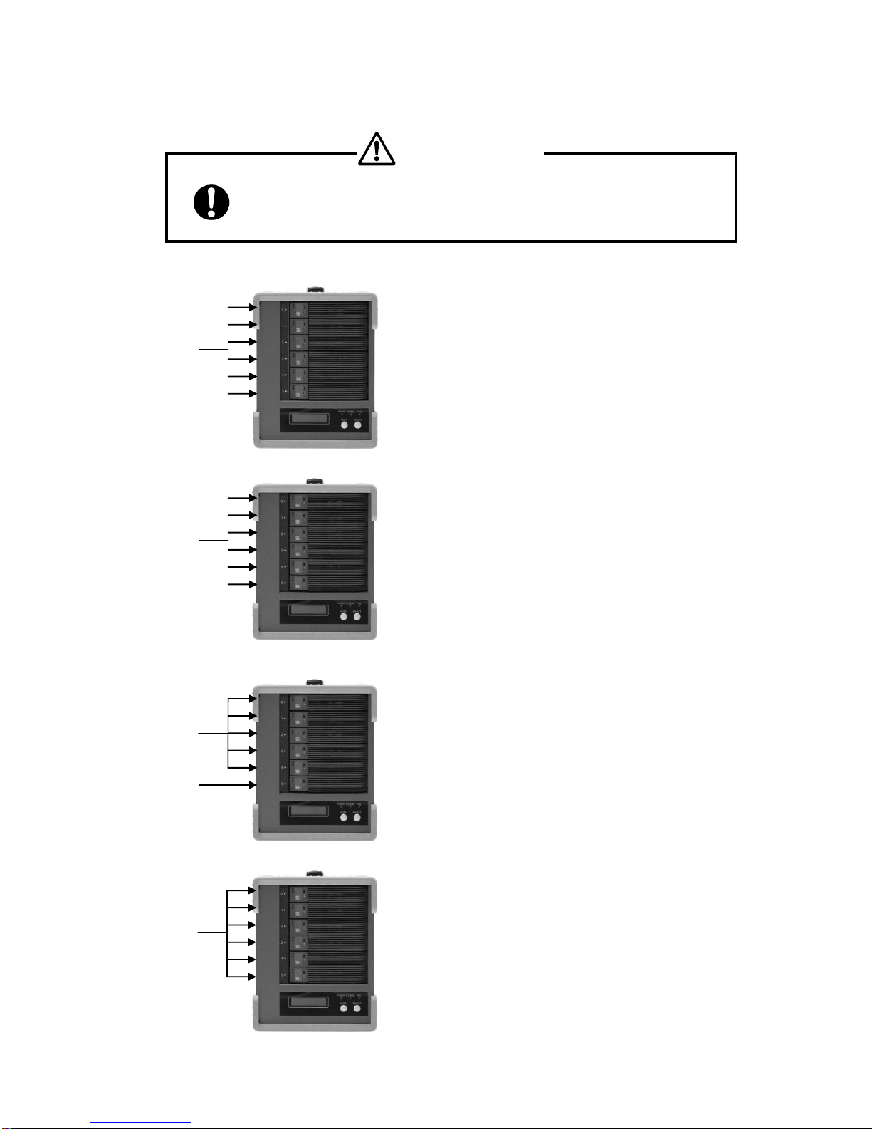
1.3 RAID Mode Explanation
● Any change of RAID mode will cause data rebuild and data lost.
①RAID MODE 6
②RAID MODE 0
③RAID MODE 3
④RAID MODE 5
Data
Drive
Parity Data
Drive
Data and
parity are
equally
distribute
d among
6 drives
The most bottom drive is used for Parity
It allows one drive failure while data is accessing.
The data residing in failed drive can be generated from the
rest of 5 drives
Data and Parity are distributed among 6 HDDs. Since there
is no assigned disk for parity, each drive shares the same
loading in data access.
Data
Drive
All drives are used for data recording
Data is segmented and equally distributed among 6 drives.
All 6 drives will be accessed while data is read or written.
The mode provides the highest performance among all
others.
At the same time, if one drive failed, the whole data will be
lost.
Data and
Parity are
divided by
six
portions
Comparing with RAID- 5 dual parity is applied providing
even higher reliability
Allow up to two drives failure but also scarify capacity of two
drives
CAUTION
M

BR256(eSATA+USB3.0)model User Manual
-14 -
⑤RAID MODE 1
⑥RAID 0-2 DRIVE MODE
⑦RAID 1- 3 DRIVE MODE
⑧RAID MODE 10
⑨SINGLE DRIVE MODE
Data Drive
Data Drive
Data Drive
Only one drive is used. Data cannot be recovered if the
drive is failed
In general, Data at RAID 1 is written to two drives at the same
time and read from one or both of drives.
Capacity is half the of the total physical disk capacity
Only two drives RAID-0 mode. (The rest of four drives
cannot be used)
There is no parity so the data cannot be recovered if any of
drive fault.
Data Drive
Three drive mirroring mode. Similar to RAID MODE1, Data is
written to all of three drives and read only from one or two
drives. Even two drives failed, the data can still be accessible.
The rest of three drives cannot be used.
It is the combination of RAID-0 and RAID-1.
Performance and security can be raised.
Stripe across mirrored Drive 0, 1 and Drive 2, 3
Capacity is equal to 2 drives capacity. Data can be accessed
even one of both mirrored pair drives failed. The rest of two
drives cannot be used.
Data Drive
Data Drive

BIOS CORPORATION
-15 -
1.4 Contents of Packing
Please inspect if accessories are all included when the package is opened.
If you found missing items, please contact your reseller. And please keep the original packing carton
and materials.
<BR256 Accessories>
□BR256
□AC power cable×1
□eSATA cable and USB3 cable
□Drive Key
□Quick Installation Guide
□User Manual (CD-R )

BR256(eSATA+USB3.0)model User Manual
-16 -
1.5 Name and Function of each part
<Front side >
<Rear Side >
⑧
①
④
⑥
⑦
⑨
⑩
⑫
⑪
⑬
⑯
⑰
⑱
⑲
②
③
⑤
⑮
⑭

BIOS CORPORATION
-17 -
No.
Name
Function
①
HDD
Module
Hot-swappable drive module from top
No.0、No.1、No.2、No.3、No.4、No.5
②
HDD
POWER / FAIL
LED
HDD Power LED: Blue when ON, and Amber if the drive failed
When 「RAID-x RECOVERING 0%」shown on LCD, the FAIL LED
on means the HDD is under rebuilding
③
HDD
ACCESS LED
Green Flash indicates HDD being accessed
④
Lock Indicator
Orange indicates HDD module was locked
Gray indicates HDD module was unlocked
⑤
Key
Turn clockwise to lock the HDD module. Check the lock indicator to
see the status of module.
⑥
LCD
Display of BR256 status or parameter
⑦
POWER LED
Blue when system is turned on.
⑧
ACCESS LED
Green flash, when accessing the controller
⑨
FAIL LED
Orange ON when a pre-defined error encountered
⑩
MODE Button
1)Parameter Initialization (press upon power on)
2)Parameter setup. See Chapter 2
3)Stop buzzer alarm(press to turn off buzzer)
⑪
SELECT Button
Parameter setup
⑫
POWER Switch
Switch system power on/off
⑬
AC Connector
Connect AC Cable
⑭
FAN
Cooling fan
⑮
eSATA Connector
Host e-SATA connection
⑯
USB3 Connector
Host USB3.0 connection
⑰
Ethernet Link
LED
Orange ON indicates Link is setup
⑱
Ethernet Speed
LED
10Mbps Off,Green On for other speed
⑲
LAN Connector
Connect to Ethernet for web management

BR256(eSATA+USB3.0)model User Manual
-18 -
1.6 Connection
● Do not expose the unit under high temperature or directly sun light
For normal operation, adequate air condition to cool the unit is
necessary
● Never shut off the power while the drive is being accessed.
It may cause abnormal operation
● Do not use the unit over or under power input range
Unstable power input might cause the system unusable or malfunction
● Never insert or remove the cable with wet hands.
You may be electrocuted.
●When removing the drive unit, be sure to use both hands.
You may drop it, causing injury
● Do not share the power plug with other high power
device
●Do not force the plug into the connector.
Please make sure the connector type correct before insertion

BIOS CORPORATION
-19 -
※1:Upon the host selection, the shape of connector might be different
※2:It is used for web-based monitor and configuration.
●Please do not connect eSATA and USB2.0 or USB3.0 at the same time
LAN Cable※2
(Optional)
AC Power
Cable
eSATA Cable※1
Table of contents
Other BIOS Storage manuals


